Table of Contents
Advertisement
Quick Links
Advertisement
Table of Contents

Related Manuals for LevelOne FSW-0809


Summary of Contents for LevelOne FSW-0809
-
Page 1: User Manual
LevelOne FSW-0809 4+4 PoE Fast Ethernet Switch User Manual v1.0 - 0706... -
Page 2: Fcc Warning
Safety FCC Warning This equipment has been tested and found to comply with the regulations for a Class B digital device, pursuant to Part 15 of the FCC Rules. These limits are designed to provide reasonable protection against harmful interference when the equipment is operated in a commercial environment. -
Page 3: Table Of Contents
Table of Content INTRODUCTION ..........1 FEATURES............2 PACKAGE CONTENT ........3 HARDWARE DESCRIPTION......4 ..........4 RONT ANEL ...........4 ANEL LED I ..........6 NDICATORS System Power..........6 PoE status (Port 1 ~ Port 4) ......6 PoE MAX ...........7 Ethernet port status (Ports 1~8) ....7 POE RULE............8 INSTALLATION..........10 TECHNICAL SPECIFICATIONS....11... -
Page 5: Introduction
Introduction The FSW-0809 Switch integrates 100Mbps Fast Ethernet and 10Mbps Ethernet network capabilities in a highly flexible package. And this switch’s Port-1 to Port-4 are Power over Ethernet (PoE) ports, and it will automatically detects the presence of IEEE 802.3af-compliant powered device (PD) and provides power through the Port-1 to Port-4. -
Page 6: Features
Features 8 ×10/100Mbps Auto-negotiation Fast Ethernet RJ45 ports with 4-port PoE function (port-1 ~ port-4) Compliant with 802.3af specification Supports PoE power up to 15.4W for PoE port Supports PoE power up to 30W for all PoE ports Supports PoE Powered Device (PD) classification identify Each port supports auto MDI/MDIX, so there is no need to use cross-over cables or... -
Page 7: Package Content
Package Content Open the shipping cartons of the Switch and carefully unpacks its contents. The carton should contain the following items: – FSW-0809 – AC power adapter (Output: DC48V, 0.8A) – Four rubber feet – User Manual If any item is found missing or damaged, please... -
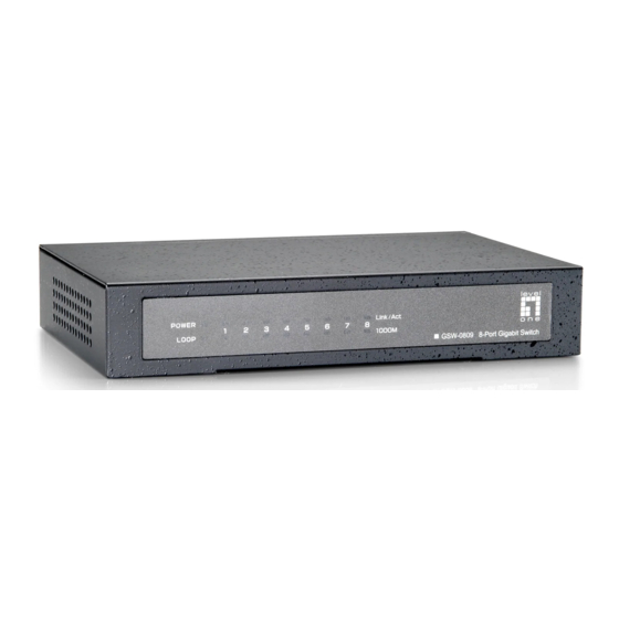
Page 8: Hardware Description
Hardware Description This chapter describes the front panel, rear panel, and LED indicators of the Switch. Front Panel LED Indicator: Comprehensive LED indicators display the status of the switch and the network (see the LED Indicators chapter below). Rear Panel PoE Ports (Port 1~4): These ports are PoE Enabled ports, the PoE port will automatically activated when a... - Page 9 Ethernet Ports (Port 5~8): These ports support network speeds of either 10Mbps or 100Mbps, and can operate in half- and full- duplex transfer modes. These ports also supports automatic MDI/MDIX crossover detection function gives true “plug and play” capability, just need to plug-in the network cable to the hub directly and don’t care if the end node is NIC (Network Interface Card) or switch and hub...
-
Page 10: Led Indicators
LED Indicators The front panel LEDs provides instant status feedback, and, helps monitor and troubleshoot when needed. System Power When the Power LED lights on, the Switch is receiving power. When the Power turns off or the power cord has improper connection. PoE status (Port 1 ~ Port 4) When the PoE powered device (PD) was Green... -
Page 11: Poe Max
PoE MAX When the system was connected to PoE PD and the power resource remain <=7.5W, the LED lights on, the system will not provide power to the additional PoE PD inserted. When the system have enough power of >7.5W. Ethernet port status (Ports 1~8) 10/100M Link/ACT: These LED indicators are lighted up when... -
Page 12: Poe Rule
PoE Rule PoE Max: this function will help to protect the PoE Switch and to stabilize the power transmitting to the powered device (PD). If the system power remain <= 7.5 watt, the PoE MAX LED will light on and the system will not provide power to the additional PoE PD to protect the PoE Switch itself and to stabilize the power transmitting to the former PoE PD... - Page 13 Priority: this function will help to protect the system when the system power was over loaded, the system will disable PoE function of the lower priority PoE port to maintain the power budget to the PoE port which is in high priority.
-
Page 14: Installation
Installation The setup of the Switch can be performed using the following steps: 1. The surface must support at least 1.5 Kg for the Switch. 2. The power outlet should be within 1.82 meters (6 feet) of the Switch. 3. Visually inspect the DC power jack and make sure that it is fully secured to the power adapter. -
Page 15: Technical Specifications
Technical Specifications General IEEE 802.3 10BASE-T Ethernet IEEE 802.3u 100BASE-TX Fast Ethernet Standards IEEE 802.3x Full Duplex Flow Control IEEE 802.3af Power over Ethernet Protocol CSMA/CD Ethernet: 10Mbps (half duplex) Data Transfer 20Mbps (full-duplex) Rate Fast Ethernet: 100Mbps (half duplex) 200Mbps (full-duplex) Topology Star... - Page 16 Performance RAM Buffer: 96K bytes per device Filtering Address 1K entries per device Table: Packet Filtering / 10Mbps Ethernet: 14,880/pps Forwarding Rate: 100Mbps Fast Ethernet: 148,800/pps MAC Address Automatic update Learning: Transmits Method: Store-and-forward...