IBM N Series Hardware Manual
System storage
Hide thumbs
Also See for N Series:
- Hardware manual (368 pages) ,
- Manual (168 pages) ,
- Implementation manual (105 pages)
Table of Contents
Advertisement
Quick Links
Advertisement
Table of Contents

Related Manuals for IBM N Series


Summary of Contents for IBM N Series
-
Page 1: Front Cover
Front cover IBM System Storage N series Hardware Guide Select the right N series hardware for your environment Understand N series unified storage solutions Take storage efficiency to the next level Roland Tretau Jeff Lin Dirk Peitzmann Steven Pemberton Tom Provost Marco Schwarz ibm.com/redbooks... - Page 3 International Technical Support Organization IBM System Storage N series Hardware Guide September 2012 SG24-7840-02...
- Page 4 Third Edition (September 2012) This edition applies to the IBM System Storage N series portfolio as of June 2012. © Copyright International Business Machines Corporation 2012. All rights reserved. Note to U.S. Government Users Restricted Rights -- Use, duplication or disclosure restricted by GSA ADP Schedule...
-
Page 5: Table Of Contents
3.2.1 N6210 and N6240 and N6240 hardware overview ......27 3.2.2 IBM N62x0 MetroCluster / gateway models ......31 3.2.3 IBM N62x0 series technical specifications . - Page 6 4.2.1 Base components ..........37 4.2.2 IBM N series N7950T slot configuration rules......40 4.2.3 N7950T hot-pluggable FRUs .
- Page 7 8.7.2 N series and expansion unit failure ........
- Page 8 Chapter 14. Designing an N series solution ....... . .
- Page 9 Chapter 16. Basic N series administration ........
- Page 10 Start with the hardware ........... 296 viii IBM System Storage N series Hardware Guide...
- Page 11 N series to NetApp model reference ........
- Page 12 IBM System Storage N series Hardware Guide...
-
Page 13: Notices
IBM representative for information on the products and services currently available in your area. Any reference to an IBM product, program, or service is not intended to state or imply that only that IBM product, program, or service may be used. Any functionally equivalent product, program, or service that does not infringe any IBM intellectual property right may be used instead. -
Page 14: Trademarks
IBM at the time this information was published. Such trademarks may also be registered or common law trademarks in other countries. A current list of IBM trademarks is available on the Web at http://www.ibm.com/legal/copytrade.shtml... -
Page 15: Preface
This IBM® Redbooks® publication provides a detailed look at the features, benefits, and capabilities of the IBM System Storage® N series hardware offerings. The IBM System Storage N series systems can help you tackle the challenge of effective data management by using virtualization technology and a unified storage architecture. The N series delivers low- to high-end enterprise storage and data management capabilities with midrange affordability. - Page 16 IT solution architect, pre-sales specialist, consultant, instructor, and enterprise IT customer. He is a member of the IBM Technical Experts Council for Australia and New Zealand (TEC A/NZ), has multiple industry certifications, and is the co-author of five previous IBM Redbooks.
-
Page 17: Now You Can Become A Published Author, Too
Your comments are important to us! We want our books to be as helpful as possible. Send us your comments about this book or other IBM Redbooks publications in one of the following ways: Use the online Contact us review Redbooks form found at: ibm.com/redbooks... -
Page 18: Stay Connected To Ibm Redbooks
Follow us on Twitter: http://twitter.com/ibmredbooks Look for us on LinkedIn: http://www.linkedin.com/groups?home=&gid=2130806 Explore new Redbooks publications, residencies, and workshops with the IBM Redbooks weekly newsletter: https://www.redbooks.ibm.com/Redbooks.nsf/subscribe?OpenForm Stay current on recent Redbooks publications with RSS Feeds: http://www.redbooks.ibm.com/rss.html IBM System Storage N series Hardware Guide... -
Page 19: Summary Of Changes
This revision reflects the addition, deletion, or modification of new and changed information described below. New information The N series hardware portfolio has been updated reflecting the June 2012 status quo. Information and changed in Data ONTAP 8.1 have been included. High-Availability and MetroCluster information has been updated to including SAS shelf technology. - Page 20 IBM System Storage N series Hardware Guide...
-
Page 21: Part 1. Introduction To N Series Hardware
Introduction to N series Part hardware This part introduces the N series hardware, including the storage controller models, disk expansion shelves, and cabling recommendations. It also addresses some of the hardware functions, including active/active controller clusters, MetroCluster, NVRAM and cache memory, and RAID-DP protection. - Page 22 IBM System Storage N series Hardware Guide...
-
Page 23: Chapter 1. Introduction To Ibm System Storage N Series
Chapter 1. Storage N series The IBM System Storage N series offers additional choices to organizations that face the challenges of enterprise data management. The IBM System Storage N series is designed to deliver high-end value with midrange affordability. Built-in enterprise serviceability and manageability features help to support customer efforts to increase reliability, simplify, and unify storage infrastructure and maintenance, and deliver exceptional economy. -
Page 24: Overview
This section introduces the IBM System Storage N series and describes its hardware features. The IBM System Storage N series provides a range of reliable, scalable storage solutions for a variety of storage requirements. These capabilities are achieved by using network access protocols such as Network File System (NFS), Common Internet File System (CIFS), HTTP, FTP, and iSCSI. -
Page 25: Ibm System Storage N Series Hardware
These sections address the N series models available at the time of this writing. Figure 1-2 on page 6 identifies all the N series models released by IBM to date that belong to the N3000, N6000, and N7000 series line. - Page 26 Easy-to-Use Back-up and Restore Processes 136 / 272 TB 144 / 374 TB 144 / 432 TB* N series Unified Storage Architecture provides unmatched simplicity * Max capacity with 3TB HDD Figure 1-2 N series hardware portfolio Features and benefits include: Data compression –...
- Page 27 – Supports attachment to IBM Enterprise Storage Server® (ESS) series, IBM XIV® Storage System, and IBM System Storage DS8000® and DS5000 series. Also supports a broad range of IBM, EMC, Hitachi, Fujitsu, and HP storage subsystems. MetroCluster – Offers an integrated high-availability/disaster-recovery solution for campus and metro-area deployments.
- Page 28 – Protects against data loss because of double disk failures and media bit errors that occur during drive rebuild processes. SecureAdmin – Authenticates both the administrative user and the N series system, creating a secure, direct communication link to the N series system. – Protects administrative logins, passwords, and session commands from cleartext snooping by replacing RSH and Telnet with the strongly encrypted SSH protocol.
- Page 29 – Enables cost-effective, long-term retention of rapidly restorable disk-based backups. Storage Encryption – Provides support for Full Disk Encryption (FDE) drives in N series disk shelf storage and integration with License Key Managers, including IBM Tivoli® Key Lifecycle Manager (TKLM).
-
Page 30: Software Licensing Structure
All N series systems support the storage efficiency features shown in Figure 1-3. Storage Efficiency features Snapshot Copies ™ Save over Point-in-time copies that write only changed blocks. No performance penalty. ® RAID-DP Protection Save up to (RAID-6) ® Virtual Copies (FlexClone Protects against double disk failure with Near-zero space, instant “virtual”... -
Page 31: Entry-Level
The entry-level software structure is similar to the mid-range and high-end structures outlined in the previous section. The following changes apply: All protocols (CIFS, NFS, Fibre Channel, iSCSI) are included with entry-level systems Gateway feature is not available MetroCluster feature is not available Chapter 1. Introduction to IBM System Storage N series... -
Page 32: Data Ontap 8 Supported Systems
1.4 Data ONTAP 8 supported systems Figure 1-5 provides an overview of systems that support Data ONTAP 8. The listed systems reflect the N series product portfolio as of June 2011, and some older N series systems that are suitable to run Data ONTAP 8. -
Page 33: Chapter 2. Entry-Level Systems
Entry-level systems Chapter 2. This chapter describes the IBM System Storage N series 3000 systems, which address the entry-level segment. This chapter includes the following sections: Overview N3220 N3240 N32x0 common information N3400 N3000 technical specifications at a glance © Copyright IBM Corp. 2012. All rights reserved. -
Page 34: Overview
I/O connectivity, and onboard remote management. Figure 2-1 N3000 modular disk storage system IBM System Storage N3220 is available as a single-node (Model A12) and as a dual-node (Model A22) (active-active) base unit. The IBM System Storage N3240 consists of single-node (Model A14) and dual-node (Model A24) (active-active) base units. -
Page 35: N3220 Hardware
2.2.3 N3220 hardware The N3220 hardware has these characteristics: Based on the EXN3500 expansion shelf 24 2.5” SFF SAS disk drives – Minimum initial order of 12 disk drives Specifications (single node, 2x for dual node) – 2U, standard 19-inch rack mount enclosure (single or dual node) –... -
Page 36: N3240
Figure 2-3 shows the N3220 Single-Controller in chassis Figure 2-3 N3220 Single-Controller in chassis 2.3 N3240 This section addresses the N series 3240 models. 2.3.1 N3240 model 2857-A14 N3240 Model A14 is designed to provide a single-node storage controller with HTTP, iSCSI, NFS, CIFS, and FCP support through optional features. - Page 37 Figure 2-4 shows the front and rear view of the N3240 Figure 2-4 N3240 front and rear view Figure 2-5 shows the N3240 Single-Controller in chassis Figure 2-5 N3240 Single-Controller in chassis Chapter 2. Entry-level systems...
-
Page 38: N32X0 Common Information
Table 2-2 N32x0 controller configuration Feature code Configuration Controller with no Mezzanine Card (blank cover) 2030 Controller with dual-port FC Mezzanine Card (include SFP+) 2031 Controller with dual-port 10 GbE Mezzanine Card (no SFP+) IBM System Storage N series Hardware Guide... -
Page 39: N3400
2.5.3 N3400 hardware The IBM System Storage N3400 can provide primary and auxiliary storage for the midsize enterprise. It enables the IT department of such an organization to consolidate all of their distributed application-based storage and unstructured data into one unified, easily managed and expandable platform. - Page 40 Doing so enables Data ONTAP to manage the EXN3000 on a separate network to increase availability and stability. The ACP is shown in Figure 2-10. Figure 2-10 N 3400 communication ports IBM System Storage N series Hardware Guide...
-
Page 41: N3000 Technical Specifications At A Glance
The N3400 has the following key specifications: 2U high Up to six external enclosures EXN1000, EXN4000 expansion units Up to five external SAS enclosures EXN3000 or EXN3500 expansion units High-performance SAS infrastructure Single controller or dual controller (for HA) Unified storage: iSCSI, NAS, Fibre Channel Each controller: Up to 8 gigabit Ethernet ports and two dual 4 Gbps Fibre Channel ports Onboard remote platform management Internal SAS drive bays... - Page 42 Max capacity shown can be achieved only by using 3 TB drives under Data ONTAP 8.0.2 or later. g. Maximum aggregate size is calculated by using base 2 arithmetic (1 TB = 240 bytes). For more information about N series 3000 systems, see the following website: http://www.ibm.com/systems/storage/network/n3000/appliance/index.html...
-
Page 43: Chapter 3. Mid-Range Systems
Mid-range systems Chapter 3. This chapter addresses the IBM System Storage N series 6000 systems, which address the mid-range segment. This chapter includes the following sections: Overview Hardware N62x0 technical specifications at a glance © Copyright IBM Corp. 2012. All rights reserved. -
Page 44: Overview
I/O technologies. Maximize storage efficiency and growth and preserve investments in staff expertise and capital equipment with data-in-place upgrades to more powerful IBM System Storage N series. Improve your business efficiency by taking advantage of the N6000 series capabilities, which are also available with a Gateway feature. -
Page 45: Hardware Summary
Diagnostic LED/LCD Dual redundant hot-plug integrated cooling fans and autoranging power supplies 19 inch, rack-mountable unit N6210 The IBM System Storage N6210 includes these storage controllers: Model C20: An active/active dual-node base unit Model C10: A single-node base unit N6240... - Page 46 EXN3000 SAS/SATA expansion unit EXN3500 SAS expansion unit At least one storage expansion unit must be attached to the N series system. All eight models must be mounted in a standard 19-inch rack. None of the eight include storage in the base chassis Dynamic removal and insertion of the controller The N6000 controllers are hot pluggable.
-
Page 47: Hardware
Model upgrades are disruptive. 3.2 Hardware This section gives an overview of the N62x0 systems. 3.2.1 N6210 and N6240 and N6240 hardware overview The IBM N6210/N6240 configuration flexibility is shown in Figure 3-2. Figure 3-2 IBM N6210/N6240 configuration flexibility Chapter 3. Mid-range systems... - Page 48 Figure 3-3 shows the IBM N6270 configuration flexibility. Figure 3-3 IBM N6270 configuration flexibility Figure 3-4 shows the IBM N62x0 slots and interfaces for a Standalone Controller: 2 PCIe v2.0 (Gen 2) x 8 slots – Top full height, full length –...
- Page 49 Figure 3-5 shows the IBM N62x0 Controller I/O module. Figure 3-5 IBM N62x0 Controller I/O IBM N62x0 I/O configuration flexibility is shown in Figure 3-6. Figure 3-6 IBM N62x0 I/O configuration flexibility Chapter 3. Mid-range systems...
- Page 50 Components are not hot swappable: – Controller will panic if removed – If inserted into running IBM N6200, IOXM is not recognized until the controller is rebooted 4 full-length PCIe v1.0 (Gen 1) x 8 slots Figure 3-7 IBM N62x0 I/O Expansion Module (IOXM) Figure 3-8 displays the IBM N62x0 system board layout.
-
Page 51: Ibm N62X0 Metrocluster / Gateway Models
Figure 3-9 shows the IBM N62x0 USB Flash Module, which has the following features. It is the boot device for Data ONTAP and the environment variables It replaces CompactFlash It has the same resiliency levels as CompactFlash 2 GB density is currently used... -
Page 52: Ibm N62X0 Series Technical Specifications
SP available through Ethernet or serial console – Shares management wrench port with e0M for Ethernet • Similar to RLM and e0M on IBM N60x0 – Toggle from serial console into SP with CTRL-G – Toggle back to serial console with CTRL-D –... -
Page 53: N62X0 Technical Specifications At A Glance
SLDIAG has a CLI interface SYSDIAG used menu tables SLDIAG is used on the IBM N6210 and N6240, and all new platforms going forward. 3.3 N62x0 technical specifications at a glance Table 3-1 provides the N62x0 specifications at a glance. - Page 54 Max capacity shown can be achieved only by using 3 TB drives under Data ONTAP 8.0.2 or later h. Maximum aggregate size is calculated using base 2 arithmetic (1TB = 240 bytes). For more information about N series 6000 systems, see the following website: http://www.ibm.com/systems/storage/network/n6000/appliance/index.html...
-
Page 55: Chapter 4. High-End Systems
High-end systems Chapter 4. This chapter describes the IBM System Storage N series 7000 systems, which address the high-end segment. This chapter includes the following sections: Overview Hardware N7950T technical specifications at a glance © Copyright IBM Corp. 2012. All rights reserved. -
Page 56: Overview
EXN3000 SAS/SATA expansion unit, and the EXN3500 SAS expansion unit. At least one storage expansion unit must be attached to the N series system. The IBM System Storage N series is designed to interoperate with products capable of data transmission in the industry-standard iSCSI, CIFS, FCP, FCoE, and NFS protocols. -
Page 57: Hardware
It includes clustered failover (CFO) support (by using the required feature), which provides a failover and failback function to improve overall availability. N series systems must be mounted in a standard 19-inch rack. The N7950T includes the following hardware:... - Page 58 Flash Cache maximum 16 GB a. Depends on the DOT release Figure 4-4 shows the IBM N series N7950T Slots and Interfaces Controller Module. Figure 4-4 IBM N series N7950T Slots and Interfaces Controller Module The N7950T includes the following features: 2 onboard I/O slots (vertical) –...
- Page 59 Figure 4-5 shows the IBM N series N7950T Controller I/O. Figure 4-5 IBM N series N7950T Controller I/O Figure 4-6 shows the IBM N series N7950T I/O Expansion Module (IOXM). Figure 4-6 IBM N series N7950T I/O Expansion Module (IOXM) The N7950T IOXM has these characteristics: All PCIe v2.0 (Gen 2) slots...
-
Page 60: Ibm N Series N7950T Slot Configuration Rules
4.2.2 IBM N series N7950T slot configuration rules The following configuration rules apply to the N7950. Vertical I/O slots Vertical slots use custom form-factor cards – Look similar to standard PCIe – Cannot put standard PCIe cards into the vertical I/O slots Vertical slot rules –... -
Page 61: N7950T Cooling Architecture
• SYSDIAG booted with a separate binary – SLDIAG has a CLI interface • SYSDIAG used menu tables SLDIAG used on IBM N series N6200 series and all new platforms going forward 4.2.6 N7950T supported back-end storage The following back-end storage is supported: Shelves and modules –... -
Page 62: N7950T Guidelines
NVRAM8 and SAS I/O system boards use the QSFP connector – Mixing the cables does not cause physical damage, but the cables will not work – Label your HA and SAS cables when you remove them IBM System Storage N series Hardware Guide... -
Page 63: N7950T Sfp+ Modules
4.2.9 N7950T SFP+ modules This section provides detailed information about SFP+ modules. Figure 4-8 shows the 8 Gb SFP+ modules. Figure 4-8 8 Gb SFP+ modules Figure 4-9 shows the 10 GbE SFP+ modules. Figure 4-9 10 GbE SFP+ modules 4.3 N7950T technical specifications at a glance Table 4-2 provides the N7950T technical specifications. - Page 64 Max capacity shown can be achieved only by using 3 TB drives under Data ONTAP 8.0.2 or greater. g. Max capacity shown can be achieved only by using 3 TB drives under Data ONTAP 8.0.2 or greater. IBM System Storage N series Hardware Guide...
- Page 65 Maximum aggregate size is calculated using base 2 arithmetic (1TB = 240 bytes). For more information about N series 7000 systems, see the following website: http://www.ibm.com/systems/storage/network/n7000/appliance/index.html Chapter 4. High-end systems...
- Page 66 IBM System Storage N series Hardware Guide...
-
Page 67: Chapter 5. Expansion Units
Expansion units Chapter 5. This chapter provides detailed information for the IBM N series expansion units, also called disk shelves. This chapter includes the following sections: Shelf technology overview Expansion unit EXN3000 Expansion unit EXN3500 Expansion unit EXN4000 Self-Encrypting Drive... -
Page 68: Shelf Technology Overview
The EXN3000 SAS/SATA expansion unit is designed to provide SAS or SATA disk expansion capability for the IBM System Storage N series systems. The EXN3000 is a 4U disk storage expansion unit. It can be mounted in any industry standard 19 inch rack. The EXN3000... - Page 69 EXN3000 are installed by IBM in the plant before shipping. Requirement: For an initial order of an N series system, at least one of the storage expansion units must be ordered with at least five disk drive features.
-
Page 70: Supported Exn3000 Drives
19-inch rack. The EXN3500 provides low-cost, high-capacity SAS disk storage with slots for 24 hard disk drives for the IBM N series system storage family. The EXN3500 SAS expansion unit is shipped with no disk drives unless they are included in the order. -
Page 71: Overview
The EXN3500 SAS expansion unit is a 2U SFF disk storage expansion unit that must be mounted in an industry standard 19-inch rack. It can be attached to all N series systems except N3300, N3700, N5200, and N5500. It includes the following features:... -
Page 72: Intermix Support
EXN3000 supports only IOM3 modules: Using IOM6 modules in an EXN3000 is not supported EXN3500 supports only IOM6 modules: Using IOM3 modules in an EXN3500 is not supported IBM System Storage N series Hardware Guide... -
Page 73: Supported Exn3500 Drives
5.3.3 Supported EXN3500 drives Table 5-3 lists the drives that are supported by EXN3500 at the time of writing. Table 5-3 EXN3500 supported drives EXN3500 Minimum Data ONTAP Capacity 7.3.4, 8.0.1, 8.1 450 GB 7.3.4, 8.0.1, 8.1 600 GB 7.3.4, 8.0.1, 8.1 600 GB encrypted 5.3.4 Environmental and technical specification Table 5-4 shows the environmental and technical specifications. -
Page 74: Supported Exn4000 Drives
Table 5-5 lists the drives that are supported by EXN4000 at the time of writing. Table 5-5 EXN3000 supported drives EXN3000 Minimum Data ONTAP Capacity Fibre 7.2.5, 7.3, 8.0 300 GB Channel 7.2.5, 7.3, 8.0 450 GB 7.3.2, 8.0 600 GB IBM System Storage N series Hardware Guide... -
Page 75: Environmental And Technical Specification
5.4.2 Environmental and technical specification Table 5-6 shows the environmental and technical specifications. Table 5-6 EXN4000 environmental specifications EXN4000 Disk Rack size Weight Empty: 50.06 lb. (23 kg) Without Drives: 68 lb. (30.8 kg) With Drives: 77lb. (35 kg) Power FC: 300 GB 3.29A, 450 GB 3.59A, 600 GB 3.44A Thermal (BTU/hr) FC: 300 GB 1119, 450 GB 1119, 600 GB 1094... -
Page 76: Effect Of Self-Encryption On Data Ontap Features
This system improves security, simplifies complexity, and achieves regulation compliance more quickly and easily. It is a huge improvement over the current approach of using many different encryption key management tools for many different business purposes and IT assets. IBM System Storage N series Hardware Guide... - Page 77 Because it demands no changes to applications and servers, it is a seamless fit for virtually any IT infrastructure. For these reasons, IBM has led the IT industry in developing and promoting an exciting new security standard: Key Management Interoperability Protocol (KMIP). KMIP is an open standard designed to support the full lifecycle of key management tasks from key creation to key retirement.
- Page 78 IBM Tivoli Key Lifecycle Manager V1.0 supports the following operating systems: AIX V5.3, 64-bit, Technology Level 5300-04, and Service Pack 5300-04-02, AIX 6.1 64 bit Red Hat Enterprise Linux AS Version 4.0 on x86, 32-bit SUSE Linux Enterprise Server Version 9 on x86, 32-bit, and V10 on x86, 32-bit Sun Server Solaris 10 (SPARC 64-bit) Remember: In Sun Server Solaris, Tivoli Key Lifecycle Manager runs in a 32-bit JVM.
-
Page 79: Chapter 6. Cabling Expansions
This chapter addresses the multipath cabling of expansions. The following topics are covered: Standard multipath cabling Multipath HA cabling Cabling different expansions This chapter includes the following sections: EXN3000 and EXN3500 disk shelves cabling EXN4000 disk shelves cabling Multipath High-Availability cabling © Copyright IBM Corp. 2012. All rights reserved. -
Page 80: Exn3000 And Exn3500 Disk Shelves Cabling
HBA port A and port C always connect to the top storage expansion unit in a stack of storage expansion units. HBA port B and port D always connect to the bottom storage expansion unit in a stack of storage expansion units. IBM System Storage N series Hardware Guide... -
Page 81: Sas Shelf Interconnects
Think of the four HBA ports as two units of ports. Port A and port C are the top connection unit, and port B and port D are the bottom connection unit (Figure 6-2). Each unit (A/C and B/D) connects to each of the two ASIC chips on the HBA. If one chip fails, the HBA maintains connectivity to the stack of storage expansion units. - Page 82 Figure 6-3 shows how the SAS shelves are interconnected for two stacks with three shelves each. Figure 6-3 SAS shelf interconnect IBM System Storage N series Hardware Guide...
-
Page 83: Top Connections
6.1.3 Top connections The top ports of the SAS shelves are connected to the HA pair controllers as shown in Figure 6-4. Figure 6-4 SAS shelf cable top connections Chapter 6. Cabling expansions... -
Page 84: Bottom Connections
SAS connections. Complete the following procedure to verify that the storage expansion unit IOMs have connectivity to the controllers: 1. Enter the following command at the system console: sasadmin expander_map Tip: For Active/Active (high availability) configurations, run this command on both nodes. IBM System Storage N series Hardware Guide... -
Page 85: Connecting The Optional Acp Cables
2. Review the output and perform the following steps: – If the output lists all of the IOMs, then the IOMs have connectivity. Return to the cabling procedure for your storage configuration to complete the cabling steps. – Sometimes IOMs are not shown because the IOM is cabled incorrectly. The incorrectly cabled IOM and all of the IOMs downstream from it are not displayed in the output. -
Page 86: Exn4000 Disk Shelves Cabling
Verify that the ACP cabling is correct by entering the following command: storage show acp For more information about cabling SAS stacks and ACP to an HA pair, see the IBM System Storage EXN3000 Storage Expansion Unit Hardware and Service Guide found at: http://www.ibm.com/storage/support/nas... -
Page 87: Multipath Fibre Channel Cabling
Tip: For N series controllers to communicate with an EXN4000 disk shelf, the Fibre Channel ports on the controller or gateway must be set for initiator. Changing behavior of the Fibre Channel ports on the N series system can be performed with the fcadmin command. -
Page 88: Multipath High-Availability Cabling
6.3 Multipath High-Availability cabling A standard N series clustered storage system has multiple single-points-of-failure on each shelf which can trigger a cluster failover (Example 6-1). Cluster failovers can disrupt access to data and put an increased workload on the surviving cluster node. -
Page 89: Chapter 7. Highly Available Controller Pairs
Highly Available controller pairs Chapter 7. IBM System Storage N series HA pair configuration consists of two nodes that are able to take over and fail over their resources or services to counterpart nodes. This function assumes that all resources can be accessed by each node. This chapter addresses aspects of determining HA pair status, and HA pair management. -
Page 90: Ha Pair Overview
Nondisruptive software upgrades: When you halt one node and allow takeover, the partner node continues to serve data for the halted node while you upgrade the node you halted. IBM System Storage N series Hardware Guide... -
Page 91: Characteristics Of Nodes In An Ha Pair
Nondisruptive hardware maintenance: When you halt one node and allow takeover, the partner node continues to serve data for the halted node. You can then replace or repair hardware in the node you halted. Figure 7-2 shows an HA pair where Controller A has failed and Controller B took over services from the failing node. -
Page 92: Preferred Practices For Deploying An Ha Pair
They each have mailbox disks or array LUNs on the root volume: – Two if it is an N series controller system (four if the root volume is mirrored by using the SyncMirror feature). – One if it is an N series gateway system (two if the root volume is mirrored by using the SyncMirror feature). -
Page 93: Comparison Of Ha Pair Types
7.1.4 Comparison of HA pair types Table 7-1 identifies the types of N series HA pair configurations (or High Availability pairs) and where each might be applied. Table 7-1 Configuration types HA pair If A-SIS Distance between Failover possible Notes... -
Page 94: Ha Pair Types And Requirements
Data from the NVRAM of one node is mirrored by its partner. Each node can take over the partner's disks or array LUNs if the partner fails. IBM System Storage N series Hardware Guide... - Page 95 See the Data ONTAP Release Notes for the list of supported systems at: http://www.ibm.com/storage/support/nas For systems with two controller modules in a single chassis, both nodes of the HA pair configuration are in the same chassis and have internal cluster interconnect.
-
Page 96: Mirrored Ha Pairs
– Avoid having both plexes of a mirror on the same disk shelf because that would result in a single point of failure. If you are using third-party storage, paths to an array LUN must be redundant. IBM System Storage N series Hardware Guide... -
Page 97: Stretched Metrocluster
License requirements The following licenses must be enabled on both nodes: cf (cluster failover) syncmirror_local 7.2.3 Stretched MetroCluster Stretch MetroCluster has the following characteristics: Stretch MetroClusters provide data mirroring and the additional ability to initiate a failover if an entire site becomes lost or unavailable. Stretch MetroClusters provide two complete copies of the specified data volumes or file systems that you indicated as being mirrored volumes or file systems in an HA pair. -
Page 98: Fabric-Attached Metrocluster
The main difference from a Stretched MetroCluster is that all connectivity between controllers, disk shelves, and between the sites is carried over IBM/Brocade Fibre Channel back-end switches switches. These are called the The back-end switches are configured with two independent and redundant Fibre Channel switch fabrics. - Page 99 A fabric-attached MetroCluster connects the two controllers nodes and the disk shelves through four SAN switches called the Back-end Switches. The Back-end Switches are IBM/Brocade Fibre Channel switches in a dual-fabric configuration for redundancy. Figure 7-5 shows a simplified Fabric-attached MetroCluster. Use a single disk shelf per Fibre Channel switch port.
-
Page 100: Configuring The Ha Pair
Consideration: Strict rules apply for how the back-end switches are configured. For more information, see the IBM System Storage N series Brocade 300 and Brocade 5100 Switch Configuration Guide found at: http://www.ibm.com/storage/support/nas Strict rules also apply for which firmware versions are supported on the back-end switches. -
Page 101: Configuration Variations For Standard Ha Pair Configurations
Consider the following questions about your installation before proceeding through the setup program: Do you want to configure VIFs for your network interfaces? How do you want to configure your interfaces for takeover? Attention: Use VIFs with HA pairs to reduce SPOFs (single points of failure). If you do not want to configure your network for use in an HA pair when you run setup for the first time, you can configure it later. -
Page 102: Enabling Licenses On The Ha Pair Configuration
Cluster enabled, nas2 is up 5. Repeat for any other licenses that you need to enable using the license type and code for each licensed product installed on the HA pair configuration. IBM System Storage N series Hardware Guide... -
Page 103: Configuring Interface Groups (Vifs)
Please enter the IP address for Network Interface vif1 []: 9.11.218.173 Please enter the netmask for Network Interface vif1 [255.0.0.0]:255.0.0.0 The Interface Groups can also be configured by using Data ONTAP FilerView or IBM System Manager for IBM N series. -
Page 104: Setting Options And Parameters
A network interface performs this role if it has a local IP address but not a partner IP address. You can assign this role by using the partner option of the ifconfig command. Example 7-6 shows how to configure a dedicated interface for the N series. Example 7-6 Configuring a dedicated interface Please enter the IP address for Network Interface e0b []: 9.11.218.160... -
Page 105: Testing Takeover And Giveback
For more information about the options, see the na_options man page at: http://www.ibm.com/storage/support/nas/ Parameters that must be the same on each node The parameters listed in Table 7-2 must be the same so that takeover is smooth and data is transferred between the nodes correctly. -
Page 106: Eliminating Single Points Of Failure With Ha Pair Configurations
HA pair storage systems. Single NIC If a NIC fails, you can initiate a failover to its partner storage system and serve data from the takeover storage system. IBM System Storage N series Hardware Guide... -
Page 107: Managing An Ha Pair Configuration
There are the following ways to manage resources and to perform takeover/giveback from one node to another node: Data ONTAP command-line interface (CLI) Data ONTAP FilerView IBM System Manager for N series Operations Manager Chapter 7. Highly Available controller pairs... -
Page 108: Managing An Ha Pair Configuration
Enabling and disabling immediate takeover of a panicked partner Halting a node without takeover Performing a takeover For more information about managing an HA pair configuration, see the IBM System Storage N series Data ONTAP 8.0 7-Mode High-Availability Configuration Guide at: http://www.ibm.com/storage/support/nas 7.4.2 Halting a node without takeover... -
Page 109: Basic Ha Pair Configuration Management
Sat Apr 9 01:49:21 GMT-7 [itsonas2: fcp.service.shutdown:info]: FCP service shutdown Sat Apr 9 01:49:21 GMT-7 [itsonas2: perf.archive.stop:info]: Performance archiver stopped. Sat Apr 9 01:49:21 GMT-7 [itsonas2: cf.fsm.takeoverOfPartnerDisabled:notice]: Cluster monitor: takeover of itsonas1 disabled (local halt in progress) Sat Apr 9 01:49:28 GMT-7 [itsonas2: cf.fsm.takeoverByPartnerDisabled:notice]: Cluster monitor: takeover of itsonas2 by itsonas1 disabled (partner halted in notakeover mode) CFE version 3.1.0 based on Broadcom CFE: 1.0.40 Copyright (C) 2000,2001,2002,2003 Broadcom Corporation. - Page 110 Example 7-11 cf status: Verification if takeover completed itsonas2(takeover)> cf status itsonas2 has taken over itsonas1. itsonas1 is ready for giveback. IBM System Storage N series Hardware Guide...
- Page 111 In the example, the N series itsonas1 rebooted when you ran the cf takeover command. When one N series storage system node is in takeover mode, the partner N series node does not reboot until the cf giveback command is run.
- Page 112 The example demonstrates how to perform these tasks by using System Manager. System Manager is a tool used for managing IBM N series available for no extra fee. System Manager can be downloaded from the IBM NAS support site found at: http://www.ibm.com/storage/support/nas...
- Page 113 Tip: Under normal conditions, you do not need to perform takeover/giveback on an IBM N series system. Usually you need to use it only if a controller needs to be halted or rebooted for maintenance. 1. As illustrated in Figure 7-6, you can perform the takeover by using System Manager and clicking Active/Active Configuration ...
- Page 114 2. Figure 7-7 shows the Active/Active takeover wizard step 1. Click Next to continue. Figure 7-7 System Manager initiating takeover step 1 3. Figure 7-8 shows the Active/Active takeover wizard step 2. Click Next to continue. Figure 7-8 System Manager initiating takeover step 2 IBM System Storage N series Hardware Guide...
- Page 115 4. Figure 7-9 shows the Active/Active takeover wizard step 3. Click Finish to continue. Figure 7-9 System Manager initiating takeover step 3 5. Figure 7-10 shows the Active/Active takeover wizard final step where takeover has been run successfully. Click Close to continue. Figure 7-10 System Manager takeover successful Chapter 7.
- Page 116 Figure 7-11 System Manager itsonas2 taken over by itsonas1 Initiating giveback by using System Manager Figure 7-12 illustrates how to perform the giveback by using System Manager. Figure 7-12 FilerView: Initiate giveback IBM System Storage N series Hardware Guide...
- Page 117 Figure 7-13 shows a successfully completed giveback. Figure 7-13 System Manager giveback successful Figure 7-14 shows that System Manager now reports the systems back to normal after a successful giveback. Figure 7-14 System Manager with systems back to normal Chapter 7. Highly Available controller pairs...
-
Page 118: Ha Pair Configuration Failover Basic Operations
You halt one of the HA pair nodes without using the -f flag. The -f flag applies only to storage systems in an HA pair configuration. If you enter the halt -f command on an N series, its partner does not take over. You initiate a takeover manually. - Page 119 its local A loop shelf count, the system concludes that it is impaired. It then prompts that node’s partner to initiate a takeover. Chapter 7. Highly Available controller pairs...
- Page 120 IBM System Storage N series Hardware Guide...
-
Page 121: Chapter 8. Metrocluster
The following topics are covered: Benefits of using MetroCluster Synchronous mirroring with SyncMirror Business continuity with IBM System Storage N series Implementing MetroCluster MetroCluster configurations Prerequisites for MetroCluster usage SyncMirror setup... -
Page 122: Overview Of Metrocluster
8.1 Overview of MetroCluster IBM N series MetroCluster, as illustrated in Figure 8-1, is a solution that combines N series local clustering with synchronous mirroring to deliver continuous availability. MetroCluster expands the capabilities of the N series portfolio. It works seamless with your host and storage environment to provide continuous data availability between two sites while eliminating the need to create and maintain complicated failover scripts. - Page 123 MetroCluster software provides an enterprise solution for high availability over wide area networks (WANs). MetroCluster deployments of N series storage systems are used for the following functions: Business continuance. Disaster recovery. Achieving recovery point and recovery time objectives (instant failover). You also have more options regarding recovery point/time objectives in conjunction with other features.
- Page 124 Figure 8-2 Logical view of MetroCluster SyncMirror Geographical separation of N series nodes is implemented by physically separating controllers and storage, creating two MetroCluster halves. For distances under 500m (campus distances), long cables are used to create Stretch MetroCluster configurations.
-
Page 125: Business Continuity Solutions
8.2 Business continuity solutions The N series offers several levels of protection with several different options. MetroCluster is just one of the options offered by the N series. MetroCluster fits into the campus-level distance requirement of business continuity as shown in Figure 8-3. -
Page 126: Planning Stretch Metrocluster Configurations
– Two onboard FC ports + dual port FC initiator adapter – Quad port FC initiator HBA (frees up onboard FC ports) Remember that all slots are in use and the N6210 cannot be upgraded with other adapters. IBM System Storage N series Hardware Guide... -
Page 127: Cabling Stretch Metroclusters
Mixed SATA and FC configurations are allowed if the following requirements are met: – There is no intermixing of Fibre Channel and SATA shelves on the same loop. – Mirrored shelves must be of the same type as their parents. The Stretch MetroCluster heads can have a distance of up to 500 m (@2 Gbps). -
Page 128: Fabric Attached Metrocluster
(minimum is two per stack) in a MetroCluster environment. A sample is shown in Figure 8-6. Figure 8-6 Cabling a Stretch MetroCluster with FibreBridges and SAS Shelves For more information about SAS Bridges, see the “SAS FibreBridges” chapter of the N series Hardware book. -
Page 129: Planning Fabric Metrocluster Configurations
Storage must be symmetric (for example, same storage on both sides). For storage that is not symmetric, but is similar, file a RPQ/SCORE. Keep in mind that N series native disk shelf disk drives are not supported with MetroClusters. Four Brocade/IBM B-Type Fibre Channel Switches are needed. For more information... - Page 130 Brocade 5100 switches. For more information about shared-switches configuration, see the Data ONTAP High Availability Configuration Guide. Attention: Always see the MetroCluster Interoperability Matrix on the IBM Support site for the latest information about components and compatibility. IBM System Storage N series Hardware Guide...
-
Page 131: Cabling Fabric Metroclusters
8.4.2 Cabling Fabric MetroClusters Figure 8-7 shows an example of a Fabric MetroCluster with two EXN4000 FC shelves on each site. Figure 8-7 Fabric MetroCluster cabling with EXN4000 Fabric MetroCluster configurations use Fibre Channel switches as the means to separate the controllers by a greater distance. -
Page 132: Synchronous Mirroring With Syncmirror
FibreBridges (minimum is two per stack) in a MetroCluster environment as shown in Figure 8-8. Figure 8-8 Cabling a Fabric MetroCluster with FibreBridges and SAS Shelves For more information about SAS Bridges, see the SAS FibreBridges Chapter in the N series Hardware book. 8.5 Synchronous mirroring with SyncMirror... - Page 133 Read performance is optimized by performing application reads from both plexes as shown in Figure 8-9. Figure 8-9 Synchronous mirroring SyncMirror is used to create aggregate mirrors. When planning for SyncMirror environments, keep in mind the following considerations: Aggregate mirrors need to be on the remote site (geographically separated) In normal mode (no takeover), aggregate mirrors cannot be served out Aggregate mirrors can exist only between like drive types.
- Page 134 0c.22 FC:B 0 FCAL 15000 0/0 137104/280790184 partner 0a.29 13 FC:A 1 FCAL 15000 0/0 137104/280790184 partner 0c.17 FC:B 0 FCAL 15000 0/0 137104/280790184 partner 0c.27 11 FC:B 0 FCAL 15000 0/0 137104/280790184 IBM System Storage N series Hardware Guide...
-
Page 135: Syncmirror Without Metrocluster
partner 0c.18 FC:B 0 FCAL 15000 0/0 137104/280790184 partner 0a.23 FC:A 1 FCAL 15000 0/0 137104/280790184 partner 0a.28 12 FC:A 1 FCAL 15000 0/0 137104/280790184 partner 0a.24 FC:A 1 FCAL 15000 0/0 137104/280790184 partner 0c.19 FC:B 0 FCAL 15000 0/0 274845/562884296 8.5.2 SyncMirror without MetroCluster SyncMirror local (without MetroCluster) is basically a standard cluster with one or both... -
Page 136: Metrocluster Zoning And Ti Zones
Fabric MetroCluster, making switch management minimal. The TI zone feature of Brocade/IBM B type switches (FOS 6.0.0b or later) allows you to control the flow of interswitch traffic. You do so by creating a dedicated path for traffic that flows from a specific set of source ports. - Page 137 You can benefit from using two ISLs per fabric (instead of one ISL per fabric) to separate out high-priority cluster interconnect traffic from other traffic. This configuration prevents contention on the back-end fabric, and provides additional bandwidth in some cases. The TI feature is used to enable this separation.
-
Page 138: Failure Scenarios
(black) by TI zones. Figure 8-13 TI Zones in MetroCluster environment 8.7 Failure scenarios The following examples illustrate some possible failure scenarios and the resulting configurations when using MetroCluster. IBM System Storage N series Hardware Guide... -
Page 139: Metrocluster Host Failure
8.7.1 MetroCluster host failure In this scenario, N series N1 (Node 1) has failed. CFO/MetroCluster takes over the services and access to its disks (Figure 8-14). The fabric switches provide the connectivity for the N series N2 and the hosts to continue to access data without interruption. -
Page 140: Metrocluster Interconnect Failure
During this period, data access is uninterrupted to all hosts. No automated controller takeover occurs. Both controller heads continue to serve its LUNs/volumes. However, mirroring and failover are disabled, thus reducing data protection. When the interconnect failure is resolved, resyncing of mirrors occurs. IBM System Storage N series Hardware Guide... -
Page 141: Metrocluster Site Failure
8.7.4 MetroCluster site failure In this scenario, a site disaster has occurred and all switches, storage systems, and hosts have been lost (Figure 8-17). To continue data access, a cluster failover must be initiated by using the cfo -d command. Both primaries now exist at data center 2, and hosting of Host1 is also done at data center 2. -
Page 142: Metrocluster Site Recovery
A cf giveback command is issued to resume normal operations (Figure 8-18). Mirrors are resynchronized and primaries and mirrors are reversed to their previous status. Figure 8-18 MetroCluster recovery IBM System Storage N series Hardware Guide... -
Page 143: Chapter 9. Fibrebridge 6500N
The ATTO FibreBridge 6500N provides an innovative bridging solution between the Fibre Channel and SAS protocols. It is an FC/SAS bridge in EXN3000 (2857-003) and EXN3500 (2857-006) storage expansion units attached to IBM System Storage N series storage systems in a MetroCluster configuration. -
Page 144: Description
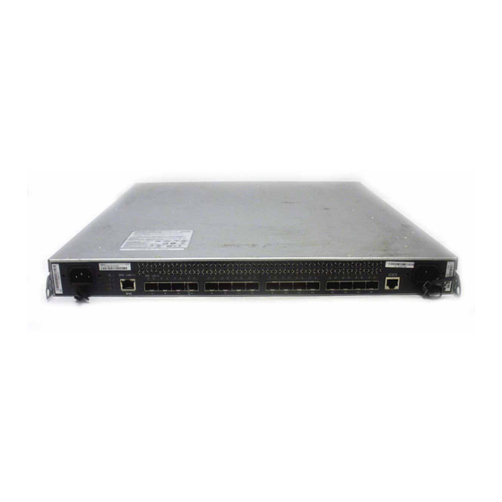
9.1 Description MetroCluster adds great availability to N series systems but is limited to Fibre Channel drive shelves only. Before 8.1, both SATA and Fibre Channel drive shelves were supported on active-active configuration in stretch MetroCluster configurations. However, both plexes of the same aggregate must use the same type of storage. - Page 145 The FC-SAS00 FibreBridge product has the following specifications: Two 8 Gb/s FC ports (optical SFP+ modules included) (4x) 6 Gb/s SAS ports (only one SAS port used) Dual 100/1000 RJ-45 Ethernet ports Serial port (RS-232) 1U enclosure Mountable into a standard 19” rack Figure 9-2 provides a a view of the bridge ports.
- Page 146 For example, if the spindle limit for N series N62x0 is n, then despite the two controllers, the spindle limit for a N62x0 fabric MetroCluster configuration remains n.
-
Page 147: Administration And Management
IO M B Expansion Units (SAS) Figure 9-5 Fabric MetroCluster with FibreBridges N series gateway configurations do not use the FibreBridge. Storage is presented through FCP as LUNs from whatever back-end array the gateway head is front ending. 9.3 Administration and management... - Page 148 Event Management System (EMS) messages and Autosupport messages Data ONTAP commands such as storage show bridge –v FibreBridge commands such as DumpConfiguration The FibreBridge does not support SNMP in the DOT 8.1 release. IBM System Storage N series Hardware Guide...
-
Page 149: Chapter 10. Data Protection With Raid Double Parity
Converting and creating RAID groups from RAID 4 to RAID-DP Hot spare disks This chapter includes the following sections: Background Why use RAID-DP RAID-DP overview RAID-DP and double parity Hot spare disks © Copyright IBM Corp. 2012. All rights reserved. -
Page 150: Background
FlexVols FlexVols offer flexible and unparalleled functionality housed in a construct known as an aggregate . For more information about FlexVol and thin provisioning, see N series Thin Provisioning, REDP-47470, at: http://www.redbooks.ibm.com/abstracts/redp4747.html?Open Traditional single-parity RAID technology offers protection from a single disk drive failure. If a secondary event occurs during reconstruction, the RAID array might experience data corruption or a volume being lost. -
Page 151: Why Use Raid-Dp
10.2 Why use RAID-DP As mentioned earlier, traditional single-parity RAID offers adequate protection against a single event. This event can be either a complete disk failure or a bit error during a read. In either event, data is re-created by using both parity data and data that remains on unaffected disks in the array or volume. -
Page 152: Advantages Of Raid-Dp Data Protection
RAID reliability from storage vendors. To meet this demand, a new type of RAID protection called RAID Double Parity (RAID-DP) has been developed (Figure 10-4). Figure 10-4 RAID-DP IBM System Storage N series Hardware Guide... -
Page 153: Raid-Dp Overview
RAID-DP is available at no additional fee or special hardware requirements. By default, IBM System Storage N series storage systems are shipped with the RAID-DP configuration. However, IBM System Storage N series Gateways are not. The initial configuration has three drives configured as shown in Figure 10-5. -
Page 154: Raid-Dp And Double Parity
RAID 4 is used to re-create the data. RAID-DP is not engaged. In this case, the diagonal parity component of RAID-DP is a protective envelope around the row parity component. IBM System Storage N series Hardware Guide... -
Page 155: Raid 4 Horizontal Row Parity
10.4.2 RAID 4 horizontal row parity Figure 10-7 illustrates the horizontal row parity approach used in the traditional RAID 4 solution. It is the first step in establishing an understanding of RAID-DP and double parity. Figure 10-7 RAID 4 horizontal parity Figure 10-7 represents a traditional RAID 4 group that uses row parity. -
Page 156: Adding Raid-Dp Double-Parity Stripes
The first condition is that each diagonal parity stripe misses one (and only one) disk, but each diagonal misses a different disk The Figure 10-9 illustrates an omitted diagonal parity stripe (white blocks) stored on the second diagonal parity disk. IBM System Storage N series Hardware Guide... -
Page 157: Raid-Dp Reconstruction
Omitting the one diagonal stripe does not affect RAID-DP's ability to recover all data in a double-disk failure as illustrated in reconstruction example. The same RAID-DP diagonal parity conditions covered in this example are true in real storage deployments. It works even in deployments that involve dozens of disks in a RAID group and millions of rows of data written horizontally across the RAID 4 group. - Page 158 1, row 1, disk 3 parity (9 - 3 - 2 - 1 = 3). This process is shown in Figure 10-12. Figure 10-12 RAID-DP reconstruction of first horizontal block IBM System Storage N series Hardware Guide...
- Page 159 The algorithm continues determining whether additional diagonal blocks can be re-created. The upper left block is re-created from row parity, and RAID-DP can proceed in re-creating the gray diagonal block in column two, row two. See Figure 10-13. Figure 10-13 RAID-DP reconstruction simulation of gray block column two RAID-DP recovers the gray diagonal block in column two, row two.
- Page 160 When the missing diagonal block in the gold stripe is re-created, enough information is available to re-create the missing horizontal block from row parity, as shown in Figure 10-16. Figure 10-16 RAID-DP reconstruction simulation of gold horizontal block IBM System Storage N series Hardware Guide...
-
Page 161: Protection Levels With Raid-Dp
After the missing block in the horizontal row is re-created, reconstruction switches back to diagonal parity to re-creating a missing diagonal block. RAID-DP can continue in the current chain on the red stripe, as shown in Figure 10-17. Figure 10-17 RAID-DP reconstruction simulation of Red diagonal block Again, after the recovery of a diagonal block, the process switches back to row parity because it has enough information to re-create data for the one horizontal block. - Page 162 Existing aggregates and traditional volumes can be easily converted to RAID-DP by using the command [aggr | vol] options name raidtype raid_dp. Figure 10-20 shows the example itso volume as a traditional RAID4 volume. Figure 10-20 vol status command showing ‘itso” volume as traditional RAID4 volume IBM System Storage N series Hardware Guide...
- Page 163 When the command is entered, the aggregate or, as in the following examples, traditional volumes are instantly denoted as RAID-DP. However, all diagonal parity stripes still need to be calculated and stored on the second parity disk. Figure 10-21 shows using the command to convert the volume.
- Page 164 Figure 10-26 shows the completed process. If a RAID-DP group is converted to RAID4, each RAID group’s second diagonal parity disk is released and put back into the spare disk pool. Figure 10-26 RAID4 conversion instantaneous completion results IBM System Storage N series Hardware Guide...
-
Page 165: Hot Spare Disks
RAID4 and RAID-DP. Therefore, little to no changes are required for standard operational procedures used by IBM System Storage N series administrators. The commands you use for management activities on the storage controller are the same regardless of the mix of RAID4 and RAID-DP aggregates or traditional volumes. - Page 166 During reconstruction, file service can slow down. After the storage system is finished reconstructing data, replace the failed disks with new hot spare disks as soon as possible. Hot spare disks must always be available in the system. IBM System Storage N series Hardware Guide...
-
Page 167: Chapter 11. Core Technologies
Core technologies Chapter 11. This chapter addresses N series core technologies such as the WAFL file system, disk structures, and NVRAM access methods. This chapter includes the following sections: Write Anywhere File Layout (WALF) Disk structure NVRAM and system memory... -
Page 168: Write Anywhere File Layout (Walf)
11.1 Write Anywhere File Layout (WALF) Write Anywhere File Layout (WAFL) is the N series file system. At the core of Data ONTAP is WAFL, N series proprietary software that manages the placement and protection of storage data. Integrated with WAFL is N series RAID technology, which includes both single and double parity disk protection. -
Page 169: Disk Structure
ONTAP does everything, but particularly in the operation of RAID and the operation of Snapshot technology. 11.2 Disk structure Closely integrated with N series RAID is the aggregate, which forms a storage pool by concatenating RAID groups. The aggregate controls data placement and space management activities. -
Page 170: Nvram And System Memory
Caching writes early in the stack allows the N series to optimize writes to disk, even when writing to double-parity RAID. Most other storage vendors cache writes at the device driver level. -
Page 171: Intelligent Caching Of Write Requests
Therefore, it uses half or a third as much space. It is common for other vendors to point out that N series storage systems often have far less NVRAM than competing models. This is because N series storage systems actually need less NVRAM to do the same job because of their unique use of NVRAM. -
Page 172: Nvram Operation
NVRAM is not lost. After data gets to an N series storage system, it is treated in the same way whether it came through a SAN or NAS connection. As I/O requests come into the system, they first go to RAM. -
Page 173: N Series Read Caching Techniques
NVRAM can function faster if the disks can keep up. For more information about technical details of N series RAID-DP, see this document: http://www.redbooks.ibm.com/abstracts/redp4169.html?Open 11.5 N series read caching techniques The random read performance of a storage system is dependent on both drive count (total number of drives in the storage system) and drive rotational speed. -
Page 174: Introduction Of Read Caching
Read caching is the process of deciding which data to either keep or prefetch into storage system memory to satisfy read requests more rapidly. The N series uses a multilevel approach to read caching to break the link between random read performance and spindle count. - Page 175 Deciding which data to prefetch into system memory The N series read ahead algorithms are designed to anticipate what data will be requested and read it into memory before the read request arrives. Because of the importance of effective read ahead algorithms, IBM has done a significant amount of research in this area.
- Page 176 IBM System Storage N series Hardware Guide...
-
Page 177: Chapter 12. Flash Cache
Flash Cache Chapter 12. This chapter provides an overview of Flash Cache and all of its components. This chapter includes the following sections: About Flash Cache Flash Cache module How Flash Cache works © Copyright IBM Corp. 2012. All rights reserved. -
Page 178: About Flash Cache
12.2 Flash Cache module The Flash Cache option offers a way to optimize the performance of an N series storage system by improving throughput and latency. It also reduces the number of disk spindles/shelves required, and the power, cooling, and rack space requirements. -
Page 179: Data Ontap Disk Read Operation
12.3.1 Data ONTAP disk read operation In Data ONTAP before Flash Cache, when a client or host needed data and it was not currently in the system’s memory, a disk read resulted. Essentially, the system asked itself if it had the data in RAM and the answer was no, it went to the disks to retrieve it. This process is shown in Figure 12-2. -
Page 180: Saving Useful Data In Flash Cache
Data is always read from disk into memory and then stored in the module when it needs to be cleared from system memory (Figure 12-4). Figure 12-4 Data is stored in Flash Cache IBM System Storage N series Hardware Guide... -
Page 181: Reading Data From Flash Cache
12.3.4 Reading data from Flash Cache When the data is stored in the module, Data ONTAP can check to see whether it is there the next time it is needed (Figure 12-5). Figure 12-5 Read request with Flash Cache module installed When it is there, access to it is far faster than having to go to disk. - Page 182 IBM System Storage N series Hardware Guide...
-
Page 183: Chapter 13. Disk Sanitization
It also presents the Data ONTAP disk sanitization feature and briefly addresses data confidentiality, technology drivers, costs and risks, and the sanitizing operation. This chapter includes the following sections: Data ONTAP disk sanitization Data confidentiality Data ONTAP sanitization operation Disk Sanitization with encrypted disks © Copyright IBM Corp. 2012. All rights reserved. -
Page 184: Data Ontap Disk Sanitization
13.1 Data ONTAP disk sanitization IBM N series Data ONTAP includes Disk Sanitization with a separately licensable, no-cost solution as a part of every offered system. When enabled, this feature logically deletes all data on one or more physical disk drives. It does so in a manner that precludes recovery of that data by any known recovery methods. -
Page 185: Technology Drivers
As technology advances, upgrades, disk subsystem replacements, and data lifecycle management require the migration of data. To ensure that the data movement does not create a security risk by leaving data patterns behind, IBM System Storage N series offers the disk sanitization feature (Figure 13-1). -
Page 186: Data Ontap Sanitization Operation
Disk sanitization is not supported on SSD drives. It does not work on disks that belong to SnapLock compliance Aggregates until all of the files reach their retention dates. Sanitization also does not work with Array LUNs (N series Gateway). The disk sanitization command cannot be run against broken or failed disks. - Page 187 Example 13-2 shows the progress of disk sanitization, starting with sanitization on drives 8a.43, 8a.44 and 8a.45. The process then formats these drives and writes a pattern (hex 0x47) multiple times (cycles) to the disks. Example 13-2 Disk sanitization progress Tue Jun 24 02:40:10 Disk sanitization initiated on drive 8a.43 [S/N 3FP20XX400007313LSA8] Tue Jun 24 02:40:10 Disk sanitization initiated on drive 8a.44 [S/N...
-
Page 188: Disk Sanitization With Encrypted Disks
Tip: To render a disk permanently unusable and the data on it inaccessible, set the state of the disk to end-of-life by using the disk encrypt destroy command. This command only works on spare disks. IBM System Storage N series Hardware Guide... -
Page 189: Chapter 14. Designing An N Series Solution
Designing an N series solution Chapter 14. This chapter addresses the issues to consider when sizing an IBM System Storage N series storage system to your environment. The following topics are addressed: Performance and throughput Capacity requirements Effects of optional features... -
Page 190: Primary Issues That Affect Planning
The performance required from the storage subsystem is driven by the number of client systems that rely on the IBM System Storage N series, and the applications running on those systems. Keep in mind that performance involves a balance of all of the following factors:... -
Page 191: Capacity Requirements
This conversion between binary and decimal units causes most of the capacity “lost” when calculating the correct size of capacity in an N series design. These two methods represent the same capacity, a bit like measuring distance in kilometers or miles, but then using the incorrect suffix. - Page 192 Raw capacity is determined by taking the number of disks connected and multiplying by their capacity. For example, 24 disks (the maximum in the IBM System Storage N series disk shelves) times 2 TB per drive is a raw capacity of approximately 48,000 GB, or 48 TB.
- Page 193 – Disks from different batches (or vendors) can contain a slightly different number of addressable blocks. Therefore, the N series controller assigns a common maximum capacity across all drives of the same basic type. For example, this process makes all “1 TB”...
- Page 194 Another factor that affects capacity is imposed by the file system. The Write Anywhere File Layou WAFL) file system used by the IBM System Storage N series has less effect than many file systems, but the effect still exists. Generally, WAFL has a memory usage equal to 10% of the formatted capacity of a drive.
- Page 195 In general, larger environments tend to result in a higher ratio of raw to usable capacity. Attention: When introducing the N series gateway in a pre-existing environment, note that the final usable capacity is different from that available on the external disk system before being virtualized.
-
Page 196: Other Effects Of Snapshot
The effect of Snapshots is determined by these factors: N series controller: – Negligible effect on the performance of the controller: The N series snapshots use a redirect-on-write design. This design avoids most of the performance effect normally associated with Snapshot creation and retention (as seen in traditional copy-on-write snapshots on other platforms). -
Page 197: Processor Utilization
Overall, it is valuable to consider how the environment might change in the future and to engineer in flexibility from the beginning. Chapter 14. Designing an N series solution... -
Page 198: Application Considerations
In clustered environments, there is always the opportunity to spread workload across at least two active storage systems. Therefore, getting good throughput for the enterprise application is generally not difficult. IBM System Storage N series Hardware Guide... - Page 199 Microsoft Exchange Microsoft Exchange has a number of parameters that affect the total storage required of N series. The following are examples of those parameters: Number of instances With Microsoft Exchange, you can specify how many instances of an email or document are saved.
-
Page 200: Backup Servers
Each IBM System Storage N series platform has different capabilities in each of these areas. The planning process must take these characteristics into account to ensure that the backup server is capable of the workload expected. -
Page 201: Resiliency To Failure
IBM System Storage N series storage systems have a number of backup mechanisms available. With prior planning, you can deploy an environment that provides maximum protection against failure while also optimizing the storage and performance capabilities. - Page 202 These agreements affect the data and applications that run on the IBM System Storage N series storage systems. If it is determined that a Active/Active configuration is needed, it affects sizing. Rather than sizing for all data, applications, and clients serviced by one IBM System Storage N series node, the workload is instead divided over two or more nodes.
-
Page 203: Summary
This chapter provided only a high-level set of guidelines for planning. Consideration of the issues addressed maximizes the likelihood for a successful initial deployment of an IBM System Storage N series storage system. Other sources of specific planning templates exist or are under development. Locate them by using web search queries. - Page 204 IBM System Storage N series Hardware Guide...
-
Page 205: Part 2. Installation And Administration
To help perform the initial hardware and software setup, it also describes the administrative interfaces: Serial console RLM interface SSH connections At a high-level, the GUI interfaces This part includes the following chapters: Preparation and installation Basic N series administration © Copyright IBM Corp. 2012. All rights reserved. - Page 206 IBM System Storage N series Hardware Guide...
-
Page 207: Chapter 15. Preparation And Installation
Preparation and installation Chapter 15. This chapter addresses the N series System Manager tool. This tool allows you to manage the N series storage system even with limited experience and knowledge of the N series hardware and software features. System Manager helps with basic setup and administration tasks, and can help you manage multiple IBM N series storage systems from a single application. -
Page 208: Installation Prerequisites
This section describes, at a high level, some of the planning and prerequisite tasks that need to be completed for a successful N series implementation. For more information, see the N series Introduction and Planning Guide at: http://www-304.ibm.com/support/docview.wss?crawler=1&uid=ssg1S7001913 15.1.1 Pre-installation checklist Before arriving at the customer site, send the customer the relevant system specifications, and a pre-install checklist to complete. -
Page 209: Configuration Worksheet
Before powering on your storage system for the first time, use the configuration worksheet (Table 15-1) to gather information for the software setup process. For more information about completing the configuration worksheet, see the N series Data ONTAP 8.1 7-Mode Software Setup Guide at: http://www.ibm.com/support/docview.wss?uid=ssg1S7003722... - Page 210 Gateway name IPv4 address IPv6 address HTTP Location of HTTP directory Domain name Server address 1 Server address 2 Server address 3 Domain name Server address 1 Server address 2 Server address 3 IBM System Storage N series Hardware Guide...
- Page 211 Type of information Your values CIFS Windows domain WINS servers (1, 2, 3) Multiprotocol or NTFS only filer? Should CIFS create default /etc/passwd and /etc/group files? Enable NIS group caching? Hours to update the NIS cache? CIFS server name (if different from default) User authentication style: (1) Active Directory domain...
-
Page 212: Initial Hardware Setup
IP address(es) (if using Storage Encryption) Key tag name 15.3 Initial hardware setup The initial N series hardware setup includes the following steps: 1. Hardware Rack and Stack: – Storage controllers, disk shelves, and so on 2. Connectivity: – Storage controller to disk shelves –... -
Page 213: Troubleshooting If The System Does Not Boot
This section is an extract from the Data ONTAP 8.1 7-mode software setup guide. For more information about system setup, see the following documentation: http://www.ibm.com/support/docview.wss?uid=ssg1S7003722 If your system does not boot when you power it on, you can troubleshoot the problem by performing these steps: 1. - Page 214 If your system... Then... Proceed to setting up the software. Starts successfully Does not start successfully Call IBM technical support. The system might not have the boot image downloaded on the boot device. IBM System Storage N series Hardware Guide...
-
Page 215: Chapter 16. Basic N Series Administration
Basic N series administration Chapter 16. This chapter describes how to accomplish basic administration tasks on IBM System Storage N series storage systems. This chapter includes the following sections: Administration methods Starting, stopping, and rebooting the storage system © Copyright IBM Corp. 2012. All rights reserved. -
Page 216: Administration Methods
. This interface is still available for systems that are running ONTAP 7.3 or earlier, but was removed in ONTAP 8.1. To access a pre-8.1 N series through FilerView, open your browser and go to the following URL: http://<filername or ip-address>/na_admin To proceed, specify a valid user name and password. - Page 217 Figure 16-1 The help and ? commands The manual pages can be accessed by entering the man command. Figure 16-2 provides a detailed description of a command and lists options (man <command>). Figure 16-2 Results of a man command Chapter 16. Basic N series administration...
-
Page 218: N Series System Manager
For more information about System Manager, see the IBM NAS support site at: http://www.ibm.com/storage/support/nas/ 16.1.4 OnCommand OnCommand is an operations manager is an N series solution for managing multiple N series storage systems that provides these features: Scalable management, monitoring, and reporting software for enterprise-class... -
Page 219: Starting The Ibm System Storage N Series Storage System
16.2.1 Starting the IBM System Storage N series storage system The IBM System Storage N series boot code is on a CompactFlash card. After turning on the system, IBM System Storage N series boots automatically from this card. You can enter an alternative boot mode by pressing Ctrl+C and selecting the boot option. - Page 220 9.1.39.107() (ITSO-N1\administrator - root) (using security signatures) itsosj-n1> With the IBM System Storage N series storage systems, you can specify which users receive CIFS shutdown messages. By issuing the cifs terminate command, Data ONTAP, by default, sends a message to all open client connections. This setting can be changed by issuing the following command: options cifs.shutdown_msg_level 0 | 1 | 2...
- Page 221 When you shut down an N series, there is no need to specify the cifs terminate command. During shutdown, this command is run by the operating system automatically. Tip: Workstations running Windows 95/98 or Windows for Workgroups will not see the notification unless they are running WinPopup.
- Page 222 Halting the N series You can use the command line or FilerView interface to stop the N series. You can use the halt command on the CLI to perform a graceful shutdown. The -t option causes the system to stop after the number of minutes that you specify (for example, halt -t 5). The halt command stops all services and shuts down the system gracefully to the Common Firmware Environment (CFE) prompt.
- Page 223 Usually you boot the N series after you issue the halt command with the boot_ontap or bye command. These commands end the CFE prompt and restart the N series as shown in Example 16-9. Example 16-9 Starting the N series at the CFE prompt CFE>bye...
-
Page 224: Rebooting The System
The System Storage N series systems can be rebooted from the command line or from the NSM interface. Rebooting from the CLI halts the N series and then restarts it as shown in Example 16-10. Example 16-10 Rebooting from the command-line interface... -
Page 225: Part 3. Client Hardware Integration
This part addresses the functions and installation of the host utility kit software. It also describes how to configure a client system to SAN boot from an N series, and provides a high-level description of host multipathing on the N series platform. - Page 226 IBM System Storage N series Hardware Guide...
-
Page 227: Chapter 17. Host Utilities Kits
This chapter provides an overview of the purpose, contents, and functions of Host Utilities Kits (HUKs) for IBM N series storage systems. It addresses why HUKs are an important part of any successful N series implementation, and the connection protocols supported. It also provides a detailed example of a Windows HUK installation. -
Page 228: What Host Utilities Kits Are
17.2.2 Current supported operating environments IBM N series provides a SAN Host Utilities kit for every supported OS. This is a set of data collection applications and configuration scripts. These include SCSI and path timeout values, and path retry counts. -
Page 229: Functions Provided By Host Utilities
Host Utilities make sure that hosts correctly handle the behavior of the IBM N series storage system. On other operating systems such as those based on Linux and UNIX, timeout parameters need to be modified manually. -
Page 230: Preparation
Enter the hotfix number in the search box and click the Search icon. Confirming your storage system configuration Make sure that your storage system is properly cabled and the Fibre Channel and iSCSI services are licensed and started. IBM System Storage N series Hardware Guide... - Page 231 Add the iSCSI or FCP license, and start the target service. The Fibre Channel and iSCSI protocols are licensed features of Data ONTAP software. If you need to purchase a license, contact your IBM or sales partner representative. Next, verify your cabling. See the FC and iSCSI Configuration Guide for detailed cabling and configuration information at: http://www.ibm.com/storage/support/nas/...
- Page 232 Hyper-V operating system. The iSCSI Initiator Properties dialog is available from Administrative Tools. A Windows Vista iSCSI connection to IBM N series storage is supported only on Hyper-V virtual machines. SUSE Linux...
-
Page 233: Running The Host Utilities Installation Program
Go to the IBM NAS support website. b. Sign in with your IBM ID and password. If you do not have an IBM ID or password, click the Register link, follow the online instructions, and then sign in. Use the same process if you are adding new N series systems and serial numbers to an existing registration. -
Page 234: Host Configuration Settings
Select the N series software you want to download, and then select the Download view. d. Use the Software Packages link on the website presented, and follow the online instructions to download the software. 3. Run the executable file, and follow the instructions on the window. -
Page 235: Overview Of Settings Used By The Host Utilities
For Windows Server 2008 or Windows Server 2008 R2, use the Windows Storage Explorer application to display the WWPNs. For Windows Server 2003, use the Microsoft fcinfo.exe program. You can instead use the HBA manufacturer's management software if it is installed on the Windows host. -
Page 236: Setting Up Luns
For iSCSI connections, create an iSCSI igroup using the iSCSI node name of the host. For systems that use both FC and iSCSI connections to the same LUN, create two igroups: One for FC and one for iSCSI. Then map the LUN to both igroups. IBM System Storage N series Hardware Guide... -
Page 237: About Mapping Luns For Windows Clusters
You must explicitly create the additional connections. 17.5.5 Accessing LUNs on hosts This section addresses how to make LUNs on N series storage subsystems accessible to hosts. Chapter 17. Host Utilities Kits... - Page 238 If you format the disk as NTFS, be sure to select the Perform a quick format option. The procedures for initializing disks vary depending on which version of Windows you are running on the host. For more information, see the Windows Disk Management online Help. IBM System Storage N series Hardware Guide...
-
Page 239: Chapter 18. Boot From San
Channel Protocol (FCP) SAN boot for your server. This process uses a LUN from an FCP SAN-attached N series storage system. It explains the concept of SAN boot and general prerequisites for using this technique. Implementations on the following operating systems... -
Page 240: Overview
You can have data (boot image and application data) mirrored over the SAN between a primary site and a recovery site. With this configuration, servers can take over at the secondary site if a disaster occurs on servers at the primary site. IBM System Storage N series Hardware Guide... -
Page 241: Configure San Boot For Ibm System X Servers
You must configure your SAN zoning or remove (disconnect) the HBA cables to leave only one path active. This implementation does not make any testing statements about supported configurations. Always see the IBM System Storage N series interoperability matrix for FC and iSCSI SAN, available at: http://www.ibm.com/systems/storage/network/interophome.html In addition, review the supported configuration for your server and operating system. -
Page 242: Preferred Practices
(2865-A20) 18.2.2 Preferred practices These guidelines that help you get the most out of your N series: Fibre Channel queue depth: To avoid host queuing, the host queue depths should not exceed the target queue depths on a per-target basis. For more information about target queue depths and system storage controllers, see the FCP Configuration Guide at: http://www.ibm.com/storage/support/nas/... - Page 243 – Some administrators concerned about paging performance might opt to keep the pagefile on a local disk while storing the operating system on an N series SAN. There are issues with this configuration as well.
-
Page 244: Basics Of The Boot Process
3. Set the boot device: Although multiple devices can be bootable (the CD, a disk drive, network adapter, storage HBA), only one can be the actual boot device. The BIOS ready determine the correct boot device order based on each device’s status and the stored configuration. IBM System Storage N series Hardware Guide... -
Page 245: Configuring San Booting Before Installing Windows Or Linux Systems
3. Configure the PC BIOS boot order to make the LUN the first disk device. For more information about SAN booting, including restrictions and configuration recommendations, see Support for FCP/iSCSI Host Utilities on Windows at: https://www-304.ibm.com/systems/support/myview/supportsite.wss/selectproduct?taski nd=7&brandind=5000029&familyind=5364556&typeind=0&modelind=0&osind=0&psid=sr&conti nue.x=1 Fore more infomation about Linux Support for FCP/iSCSI Host Utilities, see: http://www-304.ibm.com/systems/support/myview/supportsite.wss/selectproduct?taskin... - Page 246 4. Record the WWPN for the HBA. Obtaining the WWPN by using Qlogic Fast!UTIL To obtain the WWPN by using Qlogic Fast!UTIL, perform these steps: 1. Reboot the host. 2. Press Ctrl+Q to access BootBIOS. IBM System Storage N series Hardware Guide...
- Page 247 3. BootBIOS displays a menu of available adapters. Select the appropriate HBA and press Enter as shown in Figure 18-4. Figure 18-4 Selecting host adapter 4. The Fast!UTIL options are displayed. Select Configuration Settings and press Enter as shown in Figure 18-5. Figure 18-5 Fast!UTIL Options panel Chapter 18.
- Page 248 AMD Opteron 64-bit systems. It also enables you to designate a Fibre Channel drive, such as a storage system LUN, as the host's boot device. BootBIOS firmware is installed on the HBA that you purchased. IBM System Storage N series Hardware Guide...
- Page 249 Requirement: Ensure that you are using the version of firmware required by this FCP Windows Host Utility. BootBIOS firmware is disabled by default. To configure SAN booting, you must first enable BootBIOS firmware and then configure it to boot from a SAN disk. You can enable and configure BootBIOS on the HBA by using one of the following tools: Emulex LP6DUTIL.EXE: The default configuration for the Emulex expansion card for x86 BootBIOS in the Universal Boot Code image is not enabled at startup.
- Page 250 4. From the Configure Adapter’s Parameters menu, select 1 to enable the BIOS as shown in Figure 18-10. Figure 18-10 Configure the adapter’s parameters panel 5. This panel shows the BIOS disabled. Select 1 to enable the BIOS as shown in Figure 18-11. Figure 18-11 Enable/disable BIOS panel IBM System Storage N series Hardware Guide...
- Page 251 The BIOS is now enabled (Figure 18-12). Figure 18-12 Enable BIOS success panel 6. Press Esc to return to the configure adapter’s parameters menu as shown in Figure 18-13. Figure 18-13 Configure adapter’s parameters panel Chapter 18. Boot from SAN...
- Page 252 8. The eight boot entries are zero by default. The primary boot device is listed first, it is the first bootable device. Select a boot entry to configure and select 1 as shown in Figure 18-15. Figure 18-15 Configure boot device panel IBM System Storage N series Hardware Guide...
- Page 253 Clarification: In target device failover, if the first boot entry fails because of a hardware error, the system can boot from the second bootable entry. If the second boot entry fails, the system boots from the third bootable entry, and so on, up to eight distinct entries.
- Page 254 Generally, use the WWPN for all boot-from-SAN configurations. Select item 1 to boot this device using the WWPN as shown in Figure 18-19. Figure 18-19 Selecting how the boot device is identified IBM System Storage N series Hardware Guide...
- Page 255 13.After this process is complete, press X to exit and save your configuration as shown in Figure 18-20. Your HBA’s BootBIOS is now configured to boot from a SAN on the attached storage device. Figure 18-20 Exit Emulex Boot Utility and saved boot device panel 14.Press Y to reboot your system as shown in Figure 18-21.
- Page 256 If the primary boot device is unavailable, the host boots from the next available device in the list. Select the first Fibre Channel adapter port and press Enter as shown in Figure 18-23. Figure 18-23 Qlogic Fast!UTIL menu IBM System Storage N series Hardware Guide...
- Page 257 4. Select Configuration Settings and press Enter as shown in Figure 18-24. IBM System Storage™ N series – Unified Storage Solutions © 2007 IBM Corporation Figure 18-24 Configuration settings for QLE2462 adapter panel 5. Select Adapter Settings and press Enter as shown in Figure 18-25.
- Page 258 Figure 18-26 Enabling host adapter BIOS 7. Press Esc to return to the Configuration Settings panel. Scroll to Selectable Boot Settings and press Enter as shown in Figure 18-27. Figure 18-27 Accessing selectable boot settings IBM System Storage N series Hardware Guide...
- Page 259 8. Scroll to Selectable Boot as shown in Figure 18-28. – If this option is disabled, press Enter to enable it. – If this option is enabled, go to the next step. Figure 18-28 Enabling selectable boot in Selectable Boot Settings panel 9.
- Page 260 There can be slight differences within the System BIOS configuration and setup utility depending on the server model and BIOS version that are used. Knowledge of BIOS and ROM memory space usage can be required in certain situations. Some older PC architecture IBM System Storage N series Hardware Guide...
- Page 261 PCI error allocation message during the boot process. To avoid this error, disable the boot options in the HBAs that are not being used for SAN boot installation. To configure the IBM BIOS setup program, perform these steps: 1. Reboot the host.
- Page 262 Phoenix BIOS 4 Release 6 To configure Phoenix BIOS to boot from the Emulex HBA, perform these steps: 1. Reboot the host. 2. Press F2 to enter BIOS setup. 3. Navigate to the Boot tab. IBM System Storage N series Hardware Guide...
-
Page 263: Windows 2003 Enterprise Sp2 Installation
4. The Boot tab lists the boot device order. Ensure that the HBA is configured as the first boot device. Select Hard Drive. 5. Configure the LUN as the first boot device. 18.2.5 Windows 2003 Enterprise SP2 installation This section describes installation procedures for Windows 2003 Enterprise SP2. Copying the SAN boot drivers When you boot from a LUN, you must ensure that the operating system on the LUN has the required HBA driver for booting from a LUN. -
Page 264: Windows 2008 Enterprise Installation
Full installation supports GUI, and no roles such as print, file, or DHCP are installed by default. Core installation does not support any GUI. It supports only command line and Windows power shell, which is why it does not require higher memory and disk. IBM System Storage N series Hardware Guide... - Page 265 A few boot configuration changes were introduced in the Windows 2008 server. The major change is that Boot Configuration Data (BCD) stores contain boot configuration parameters. These parameters control how the operating system is started in Microsoft Windows Server 2008 operating systems. These parameters were previously in the Boot.ini file (in BIOS-based operating systems) or in the nonvolatile RAM (NVRAM) entries (in Extensible Firmware Interface-based operating systems).
- Page 266 Figure 18-38 Rebooting the server 2. Select an installation language, regional options, and keyboard input, and click Next, as shown in Figure 18-39. Figure 18-39 Selecting the language to install, regional options, and keyboard input IBM System Storage N series Hardware Guide...
- Page 267 3. Click Install now to begin the installation process as shown in Figure 18-40. Figure 18-40 Selecting Install now 4. Enter the product key and click Next as shown in Figure 18-41. Figure 18-41 Entering the product key Chapter 18. Boot from SAN...
- Page 268 5. Select I accept the license terms and click Next as shown in Figure 18-42. Figure 18-42 Accepting the license terms 6. Click Custom (advanced) as shown in Figure 18-43. Figure 18-43 Selecting the Custom installation option IBM System Storage N series Hardware Guide...
- Page 269 7. If the window shown in Figure 18-44 does not show any hard disk drives, or if you prefer to install the HBA device driver now, click Load Driver. Figure 18-44 Where do you want to install Windows? window 8. As shown in Figure 18-45, insert appropriate media that contains the HBA device driver files and click Browse.
-
Page 270: Red Hat Enterprise Linux 5.2 Installation
HBAs to the igroup, and install the FCP Windows Host Utilities. 18.2.7 Red Hat Enterprise Linux 5.2 installation This section shows how to install Red Hat Enterprise Linux 5.2 boot from SAN with an IBM System x server. Prerequisite: Always check hardware and software, including firmware and operating system compatibility, before you implement SAN boot in different hardware or software environments. -
Page 271: Red Hat Enterprise Linux
Linux boot process This section is an overview of the Linux boot process in an x86 environment. In general, the boot process is as shown in Figure 18-47. Figure 18-47 Linux boot process System BIOS The process starts when you power up or reset your System x. The processor runs the basic input/output system (BIOS) code, which then runs a power-on self-test (POST) to check and initialize the hardware. -
Page 272: Boot From San And Other Protocols
WWPN for all additional HBAs to the igroup, and install the FCP Linux Host Utilities. IBM LUNs connected by way of a block protocol (for example, iSCSI, FCP) to Linux hosts using partitions might require special partition alignment for best performance. For more information about this issue, see: http://www.ibm.com/support/docview.wss?uid=ssg1S1002716&rs=573... - Page 273 FCoE encapsulates the Fibre Channel frame in an Ethernet packet to enable transporting storage traffic over an Ethernet interface. By transporting the entire Fibre Channel frame in Ethernet packets, FCoE makes sure that no changes are required to Fibre Channel protocol mappings, information units, session management, exchange management, and services.
- Page 274 IBM System Storage N series Hardware Guide...
-
Page 275: Chapter 19. Host Multipathing
Host multipathing Chapter 19. This chapter introduces the concepts of host multipathing. It addresses the installation steps and describes the management interface for the Windows, Linux, and IBM AIX operating systems. The following topics are covered: Overview Multipathing software options, including ALUA... -
Page 276: Overview
19.1 Overview Multipath I/O (MPIO) provides multiple storage paths from hosts (initiators) to their IBM System Storage N series targets. The multiple paths provide redundancy against failures of hardware such as cabling, switches, and adapters. They also provide higher performance thresholds by aggregation or optimum path selection. -
Page 277: Multipathing Software Options
19.2 Multipathing software options The multipathing solution can be provided by: Third-party vendors: – Storage vendors provide support for their own storage arrays such as the IBM Data ONTAP DSM for Windows. These solutions are generally specific to the particular vendor’s equipment. -
Page 278: Native Multipathing Solution
ALUA, the multipath vendor can use standard SCSI commands to determine the access characteristics. ALUA was implemented in Data ONTAP 7.2. iSCSI in N series controllers has no secondary path, and because link failover operates differently from Fibre Channel, ALUA is not supported on iSCSI connections. - Page 279 3. If using SnapDrive, verify that there are no settings that disable the ALUA set in the configuration file. ALUA is enabled or disabled on the igroup mapped to a LUN on the N series controller. The default ALUA setting in Data ONTAP varies by version and by igroup type. Check the output of the igroup show -v <igroup name>...
- Page 280 IBM System Storage N series Hardware Guide...
-
Page 281: Part 4. Performing Upgrades
Performing upgrades Part This part addresses the design and operational considerations for nondisruptive upgrades on the N series platform. It also provides some high-level example procedures for common hardware and software upgrades. This part contains the following chapters: System NDU Hardware upgrades ©... - Page 282 IBM System Storage N series Hardware Guide...
-
Page 283: Chapter 20. Designing For Nondisruptive Upgrades
Note: Upgrade the system software or firmware in the following order: 1. System firmware 2. Shelf firmware 3. Disk firmware This chapter includes the following sections: System NDU Shelf firmware NDU Disk firmware NDU ACP firmware NDU RLM firmware NDU © Copyright IBM Corp. 2012. All rights reserved. -
Page 284: System Ndu
20.1.2 Supported Data ONTAP upgrades Support for system NDU differs slightly according to the protocols that are in use on the system. The following sections address those different protocols. IBM System Storage N series Hardware Guide... - Page 285 Support for NFS environments Table 20-1 shows the major and minor upgrades that have NDU support in an NFS environment. Table 20-1 NDU support for NFS environments Source Data ONTAP version Minor version NDU Major version NDU supported supported 7.1, 7.1.1 7.1.2 (and later) 7.2, 7.2.1, 7.2.2 7.2.3 (and later)
-
Page 286: System Ndu Hardware Requirements
NDU, see 20.1.4, “System NDU software requirements” on page 266. 20.1.3 System NDU hardware requirements System NDU is supported on any IBM N series storage controller, or gateway, hardware platform that supports the HA pair controller configuration. Both storage controllers must be identical platforms. - Page 287 N7750 N7950 Restriction: Major NDU from Data ONTAP 7.2.2L1 to 7.3.1 is not supported on IBM N3300 systems that contain aggregates larger than 8 TB. Therefore, a disruptive upgrade is required. Aggregates larger than 8 TB prevent the system from running a minor version NDU from Data ONTAP 7.2.2L1 to 7.2.x.
-
Page 288: Prerequisites For A System Ndu
Reading the latest documentation Review the Data ONTAP Upgrade Guide for the version to which you are upgrading, not the version from which you are upgrading. These documents are available on the IBM Support site. Verify that the system and hosts (if applicable) fulfill the requirements for upgrade. -
Page 289: Steps For Major Version Upgrades Ndu In Nas And San Environments
20.1.6 Steps for major version upgrades NDU in NAS and SAN environments The procedural documentation for running an NDU is in the product documentation on the IBM Support site. See the “Upgrade and Revert Guide” of the product documentation for the destination release of the planned upgrade. -
Page 290: System Commands Compatibility
20.2 Shelf firmware NDU The IBM N series disk shelves incorporate controller modules that support firmware upgrades as a means of providing greater stability or functionality. Because of the need for uninterrupted data I/O access by clients, these firmware updates can, depending on the model of module involved, be performed nondisruptively. -
Page 291: Upgrading The Shelf Firmware
Manual firmware upgrade A manual shelf firmware upgrade before the Data ONTAP NDU operations is the preferred method. Download the most recent firmware from the IBM Support site to the controller's /etc/shelf_fw directory, then issue the storage download shelf command. -
Page 292: Upgrading The At-Fcx Shelf Firmware During System Reboot
HA pair configurations. 20.3 Disk firmware NDU Depending on the configuration, the N series allows you to conduct disk firmware upgrades nondisruptively (without affecting client I/O). Disk firmware NDU upgrades target one disk at a time, which reduces the performance effect and results in zero downtime. -
Page 293: Upgrading The Disk Firmware Non-Disruptively
20.3.2 Upgrading the disk firmware non-disruptively Nondisruptive upgrades are performed by downloading the most recent firmware from the IBM Support site to the controller's /etc/disk_fw directory. Updates start automatically for any disk drives that are eligible for an update. Data ONTAP polls approximately once per minute to detect new firmware in the /etc/disk_fw directory. -
Page 294: Acp Firmware Ndu
To upgrade ACP firmware manually, you must download the most recent firmware from the IBM Support site to the controller's /etc/acpp_fw directory. Use the storage download acp command to start the ACP firmware upgrade. It downloads the firmware to all ACPs in an active state unless a specific ACP is identified by using the storage download acp command. -
Page 295: Rlm Firmware Ndu
RLM command-line interface. Both procedures are nondisruptive upgrades of the RLM firmware. Perform nondisruptive upgrades by downloading the latest RLM firmware from the IBM Support site to a web server on a network accessible by the controller. After the firmware is n... - Page 296 IBM System Storage N series Hardware Guide...
-
Page 297: Chapter 21. Hardware And Software Upgrades
Hardware and software upgrades Chapter 21. This chapter addresses high-level procedures for some common hardware and software upgrades. This chapter includes the following sections: Hardware upgrades Software upgrades © Copyright IBM Corp. 2012. All rights reserved. -
Page 298: Hardware Upgrades
Attention: The high-level procedures described in the section are of a generic nature. They are not intended to be your only guide to performing a hardware upgrade. For more information about procedures that are specific to your environment, see the IBM support site. -
Page 299: Upgrading A Storage Controller Head
21.1.3 Upgrading a storage controller head The model of N series controller can be upgraded from without needing to migrate any data (“data in place”). For example, to replace a N5000 head with a N6000 head, perform these steps: 1. Prepare the old controller: a. -
Page 300: Upgrading To Data Ontap 7.3
21.2.1 Upgrading to Data ONTAP 7.3 To identify the compatible IBM System Storage N series hardware for the currently supported releases of Data ONTAP, see the IBM System Storage N series Data ONTAP Matrix at: http://www.ibm.com/storage/support/nas Update the installed N series storage system to the latest Data ONTAP release. Metrics demonstrate reliability over many customer installations and completion of compatibility testing with other products. -
Page 301: Upgrading To Data Ontap 8.1
Generally, DOT8 requires you to use 64-bit hardware. Older 32-bit hardware is not supported. At the time of writing, the following systems and hardware are supported: N series: N7900, N7700, N6070, N6060, N6040, N5600, N5300, N3040 Performance acceleration cards (PAM) - Page 302 Revert considerations The N series does not support NDU for the revert process for DOT 8 7-mode. The following restrictions apply to the revert process: User data is temporarily offline and unavailable during the revert. You must plan when the data is offline to limit the unavailability window and make it fall within the timeout window for the Host attach kits.
- Page 303 TUCSON1> revert_to 7.3 autoboot TUCSON1> version Data ONTAP Release 7.3.2: Thu Oct 15 04:39:55 PDT 2009 (IBM) TUCSON1> You can use the netboot option for a fresh installation of the storage system. This installation boots from a Data ONTAP version stored on a remote HTTP or Trivial File Transfer Protocol (TFTP) server.
- Page 304 Example 21-4. Example 21-4 sysconfig command N6070A> sysconfig -a Data ONTAP Release 7.3.7: Thu May 3 04:32:51 PDT 2012 (IBM) System ID: 0151696979 (N6070A); partner ID: 0151697146 (N6070B) System Serial Number: 2858133001611 (N6070A) System Rev: A1...
- Page 305 Next, review all necessary documentation including the Data ONTAP Upgrade Guide and Data ONTAP Release Notes for the destination version of Data ONTAP. You can obtain these documents from the IBM support website at: http://www.ibm.com/storage/support/nas Chapter 21. Hardware and software upgrades...
- Page 306 Attention: Ensure that all firmware is up to date. If you are experiencing long boot times, you can disable the auto update of disk firmware before downloading Data ONTAP by using the following command: options raid.background_disk_fw_update.enable off IBM System Storage N series Hardware Guide...
- Page 307 Figure 21-2 Boot loader Next, use the autoboot command and perform another reboot if DOT 8 did not load immediately after the flash update. After the boot process is complete, verify the version by using the version and sysconfig commands as shown in Example 21-6. Example 21-6 Version and sysconfig post upgrade N6070A>...
- Page 308 IBM System Storage N series Hardware Guide...
-
Page 309: Part 5
Part 5 Appendixes Part © Copyright IBM Corp. 2012. All rights reserved. - Page 310 IBM System Storage N series Hardware Guide...
-
Page 311: Appendix A. Getting Started
Getting started Appendix A. This appendix provides information to help you document, install, and set up your IBM System Storage N series storage system. This appendix includes the following sections: Preinstallation planning Start with the hardware Power on N series... -
Page 312: Preinstallation Planning
Administration Guide or Active/Active Configuration Guide GC26-7964, for your version of Data ONTAP. 4. For information about how to set up the N series Data ONTAP, see IBM System Storage N series Data ONTAP Software Setup Guide, GC27-2206. This document describes how to set up and configure new storage systems that run Data ONTAP software. - Page 313 Table A-1 provides an initial worksheet for setting up the node. Table A-1 Initial worksheet Types of information Your values Storage system Host name If the storage system is licensed for the Network File System (NFS) protocol, the name can be no longer than 32 characters.
- Page 314 Server address 1, 2, 3 Domain name Server address 1, 2, 3 Customer Primary Name contact Phone Alternate phone Email address or IBM Web ID Secondary Name Phone Alternate phone Email address or IBM Web ID IBM System Storage N series Hardware Guide...
- Page 315 Machine location Business name Address City State Country code (value must be two uppercase letters) Postal code CIFS Windows domain WINS servers Multiprotocol or NTFS only storage system Should CIFS create default etc/passwd and etc/group files? Enter y here if you have a multiprotocol environment. Default UNIX accounts are created that are used when running user mapping.
-
Page 316: Start With The Hardware
You access the systems and manage the disk resources from a remote console by using a web browser or command line after initial setup. Otherwise, use a serial port. The ASCII terminal console enables you to monitor the boot process, configure your N series system after it boots, and perform system administration. -
Page 317: Power On N Series
2. Connect the DB-9 null modem cable to the DB-9 to RJ-45 adapter cable 3. Connect the RJ-45 end to the console port on the N series system and the other end to the ASCII terminal. 4. Connect to the ASCII terminal console. - Page 318 Fibre Channel adapter 0a. Wed May 2 03:01:27 GMT [fci.initialization.failed:error]: Initialization failed on Fibre Channel adapter 0b. Data ONTAP Release 7.2.4L1: Wed Nov 21 06:07:37 PST 2007 (IBM) Copyright (c) 1992-2007 Network Appliance, Inc. Starting boot on Wed May 2 03:01:12 GMT 2007 Wed May 2 03:01:28 GMT [nvram.battery.turned.on:info]: The NVRAM battery is turned...
- Page 319 d. At the 1-5 special boot menu, choose either option 4 or option 4a. Option 4 creates a RAID 4 traditional volume. Selecting option 4a creates a RAID-DP aggregate with a root FlexVol. The size of the root flexvol is dependant upon platform type. See Example A-3.
- Page 320 “Data ONTAP update” on page 301. 3. The system begins to boot. Complete the initial setup by answering all the installation questions as in the initial worksheet. For more information, see the IBM System Storage Data ONTAP Software Setup Guide, GA32-0530.
-
Page 321: Data Ontap Update
5. Always consider updating firmware and Data ONTAP to the preferred version. For more information, see “Data ONTAP update” on page 301. 6. Do these steps again on the second filer for N series with model A20 or A21. Data ONTAP update... -
Page 322: Obtaining The Data Ontap Software From The Ibm Nas Website
The standard update method is appropriate when you can schedule downtime for system updates. Upgrading Data ONTAP for a single node always requires downtime. Remember: Review the Data ONTAP Release Notes and IBM System Storage N series Data ONTAP Upgrade Guide for your version of Data ONTAP at: http://www.ibm.com/support/docview.wss?uid=ssg1S7001558... -
Page 323: Installing Data Ontap System Files
3. Select the Data ONTAP version. 4. Select the installation kit that you want to download. Check and confirm the license agreement to start downloading the software. Installing Data ONTAP system files You can install Data ONTAP system files from a UNIX client, Windows client, or HTTP server. To install from a Windows client, perform these steps: 1. - Page 324 2. Map the system storage to a drive. You must log in as administrator or log in using an account that has full control on the storage system C$ directory. a. Click Tools Map Network Drive (Figure A-1). Figure A-1 Map Network Drive IBM System Storage N series Hardware Guide...
- Page 325 b. Enter the network mapping address (Figure A-2). Figure A-2 Mapping address c. Enter a user name and password to access the storage system (Figure A-3). Figure A-3 Storage access Appendix A. Getting started...
- Page 326 Go to the drive to which you previously downloaded the software (see “Obtaining the Data ONTAP software from the IBM NAS website” on page 302). b. Double-click the files that you downloaded. A dialog box is displayed as shown in Figure A-5.
- Page 327 c. In the WinZip dialog box, enter the letter of the drive to which you mapped the storage system. For example, if you chose drive Y, replace DRIVE:\ETC with the following path: Y:\ETC See Figure A-6. Figure A-6 Extract path d.
-
Page 328: Downloading Data Ontap To The Storage System
Thu May 3 05:43:50 GMT [download.request:notice]: Operator requested download initiated download: Downloading boot device Version 1 ELF86 kernel detected.... download: Downloading boot device (Service Area) ..n3300a*> Thu May 3 05:49:44 GMT [download.requestDone:notice]: Operator requested download completed IBM System Storage N series Hardware Guide... - Page 329 -a See Example A-12. Example A-12 sysconfig -a n3300a*> sysconfig -a Data ONTAP Release 7.2.5.1: Wed Jun 25 11:01:02 PDT 2008 (IBM) System ID: 0135018677 (n3300a); partner ID: 0135018673 (n3300b) System Serial Number: 2859138306700 (n3300a) System Rev: B0 slot 0: System Board 2198 MHz (System Board XIV D0)
-
Page 330: Setting Up The Network Using Console
The easiest way to change network configuration is by using setup command. But the new contents do not take effect until the filer is rebooted. This section addresses how to change the network configuration without rebooting the filer. IBM System Storage N series Hardware Guide... -
Page 331: Changing The Ip Address
8160 127 127.0.0.1 3. If you want this IP address to be persistent after the N series is rebooted, update the /etc/hosts for IP address changes in the associated interface. For netmask and other network parameters, update the /etc/rc. You can modify this file from the N series console, CIFS, or NFS. -
Page 332: Setting Up The Dns
– To update the DNS domain name (Example A-18): options dns.domainname <domain name> Example A-18 Updating DNS domain name #---check the dns domainname--- n3300a> options dns.domainname dns.domainname (value might be overwritten in takeover) #---update n3300a> options dns.domainname itso.tucson.ibm.com IBM System Storage N series Hardware Guide... - Page 333 Sun May 6 03:41:01 GMT [n3300a: reg.options.cf.change:warning]: Option dns.domainname changed on one cluster node. n3300a> options dns.domainname dns.domainname itso.tucson.ibm.com (value might be overwritten in takeover) 3. Check that the DNS is already enabled by using the dns info command (Example A-19): options dns.enable on Example A-19 Enabling DNS n3300a>...
- Page 334 4. To make this change persistent after filer reboot, update the /etc/rc to ensure that the name server exists as shown in Figure A-13. Figure A-13 /etc/rc file IBM System Storage N series Hardware Guide...
-
Page 335: Appendix B. Operating Environment
Operating environment Appendix B. This appendix provides information about the Physical environment and operational environment specifications of N series controller and disk shelves/ This appendix includes the following sections: N3000 entry-level systems – N3400 – N3220 – N3240 N6000 mid-range systems –... -
Page 336: N3000 Entry-Level Systems
– 100 - 120 V ac, 4 A; – 200 - 240 V ac, 2 A 50-60 Hz Noise level: – 54 dBa @ 1 m @ 23 degrees C – 7.2 bels @ 1 m @ 23 degrees C IBM System Storage N series Hardware Guide... -
Page 337: N3220
N3220 Physical Specifications IBM System Storage N3220 Model A12/A22 Width: 44.7 cm (17.61 in.) Depth: 61.9 cm (24.4 in.) with cable management arms 54.4 cm (21.4 in.) without cable management arms Height: 8.5 cm (3.4 in.) Weight: 25.4 kg (56 lb) (two controllers) -
Page 338: N6000 Mid-Range Systems
N6000 mid-range systems This section lists N6000 mid-range specifications. N6210 Physical Specifications IBM System Storage N6240 Models C10, C20, C21, E11, and E21 Width: 44.7 cm (17.6 in.) Depth: 71.3 cm (28.1 in.) with cable management arms 65.5 cm (25.8 in.) without cable management arms Height: 13 cm (5.12 in.) (times 2 for E21) -
Page 339: N6240
– 55.5 dBa @ 1 m @ 23 degrees C – 7.5 bels @ 1 m @ 23 degrees C N6240 Physical Specifications IBM System Storage N6240 Models C10, C20, C21, E11, and E21 Width: 44.7 cm (17.6 in.) Depth: 71.3 cm (28.1 in.) with cable management arms 65.5 cm (25.8 in.) without cable management arms... -
Page 340: N6270
– 200-240 V ac, 2.3 A, 50-60 Hz Noise level: – 55.5 dBa @ 1 m @ 23 degrees C – 7.5 bels @ 1 m @ 23 degrees C N7000 high-end systems This section lists N7000 high-end specifications. IBM System Storage N series Hardware Guide... -
Page 341: N7950T
– 8.1 bels @ 1 m @ 23 degrees C N series expansion shelves This section lists N series expansion shelves specifications. EXN1000 Because the EXN1000 was withdrawn from the market and is no longer being sold, it is not covered in this book. -
Page 342: Exn3000
– 7.0 bels @ 1 m @ 23 degrees C (SAS drives) operating EXN3500 Physical Specifications EXN3500 SAS expansion unit Width: 447.2 mm (17.6 in) Depth: 542.6 mm (21.4 in) Height: 85.3 mm (3.4 in) IBM System Storage N series Hardware Guide... -
Page 343: Exn4000
Weight (minimum configuration, 0 HDDs): 17.6 kg (38.9 lb) Weight (maximum configuration, 24 HDDs): 22.3 kg (49 lb) Operating Environment Temperature: – Maximum range: 10 - 40 degrees C (50 - 104 degrees F) – Recommended: 20 - 25 degrees C (68 - 77 degrees F) –... - Page 344 – 49 dBa @ 1 m @ 23 degrees C – 5 bels @ 1 m @ 23 degrees C IBM System Storage N series Hardware Guide...
-
Page 345: Appendix C. Useful Resources
Useful resources Appendix C. This appendix provides links to important online resources: N series to NetApp model reference Interoperability matrix © Copyright IBM Corp. 2012. All rights reserved. -
Page 346: N Series To Netapp Model Reference
N series to NetApp model reference This section provides a matrix of the IBM N series and OEM system types and model numbers. For the most up-to-date information, see the following websites: IBM System Storage N series Machine Types and Models (MTM) Cross Reference http://www-304.ibm.com/support/docview.wss?uid=ssg1S7001844... -
Page 347: Related Publications
Managing Unified Storage with IBM System Storage N series Operation Manager, SG24-7734 Using an IBM System Storage N series with VMware to Facilitate Storage and Server Consolidation, REDP-4211 Using the IBM System Storage N series with IBM Tivoli Storage Manager, SG24-7243 IBM System Storage N series and VMware vSphere Storage Best Practices, SG24-7871 IBM System Storage N series with VMware vSphere 4.1, SG24-7636... -
Page 348: Other Publications
Network-attached storage: http://www.ibm.com/systems/storage/network/ IBM support: Documentation: http://www.ibm.com/support/entry/portal/Documentation IBM Storage – Network Attached Storage: Resources: http://www.ibm.com/systems/storage/network/resources.html IBM System Storage N series Machine Types and Models (MTM) Cross Reference: http://www-304.ibm.com/support/docview.wss?uid=ssg1S7001844 IBM N Series to NetApp Machine type comparison table: http://www.ibm.com/support/techdocs/atsmastr.nsf/WebIndex/TD105042 Interoperability matrix: http://www-304.ibm.com/support/docview.wss?uid=ssg1S7003897... -
Page 349: Index
76 density 131 ASCII terminal console 296–297 per square foot 132 ASIC chips 61 CAT6 65 Asymmetric Logical Unit Access see ALUA CD-ROM 243 asymmetrical configurations 81 centralized administration 220 © Copyright IBM Corp. 2012. All rights reserved. - Page 350 DNS see Domain Name Service (DNS) access methods 5 Domain Name Service (DNS) 181, 284, 312 confidentiality 164 domain name 312 drives 133 setup 312–313 fault tolerance 129–130 DOT 8 286 data confidentiality 164 IBM System Storage N series Hardware Guide...
- Page 351 DOT 8 7-mode 281 Fast!UTIL 227 DOT 8.0 7-mode features 282 fault tolerance 70, 132, 220 double parity 134 FCoE 208 double-disk failure 134, 137, 143, 145 FCP 219 recovery scenario 129 SAN boot 220 scenario 141 fcstat device_map 86 double-parity RAID 134 FC-VI adapter 78 DP 136...
- Page 352 81 IBM BIOS setup 241 interconnect cables 85 IBM LUN 252 management 89 IBM System Manager for N series 87 controller 64 IBM System Storage N series 130, 145 units 81 data protection with RAID DP 129 nodes 81, 88...
- Page 353 MBR 225, 251 System Manager tool 187 Metadata 155 N3000 14, 21, 33, 43 MetroCluster 7, 31, 78, 101–102 family hardware specification 19, 21–22 and N series failure 119 hardware 19, 21 configuration 78–79, 101 N3220 14 fabric-attached 108 N3240 16...
- Page 354 129, 131 Performance Acceleration Module see Flash Cache operation 141 Phoenix BIOS 242 operation summary 141 planning overview 129, 133 pre-installation 169 protection levels 133 primary issues 170 reconstruction 129, 137 IBM System Storage N series Hardware Guide...
- Page 355 volume 143 key manager 57 random data 166 overview 55 random I/O 171 Self-Encrypting Disk see SED raw capacity 172 sequential operations 171 read caching 150, 153 sequential reads 155 details 154 sequential workload 53 read-to-write ratio 180 Serial-Attached SCSI see SAS reboot 204 service clearance 292 reconstruct data 132, 135, 137, 141, 146...
- Page 356 244 backup facilities 181 domain 72 backup tool 181 installation 244 disposal 164 pagefile 222 SCSI array driver 243 Windows Server 2003 243 storage 76 Windows Server 2008 TI zones 116 IBM System Storage N series Hardware Guide...
- Page 357 full installation option 246 installation media 246 R2 245 setup 250 workload mix 170 worksheets 294–296 Worldwide Port Name (WWPN) see WWPN Write Anywhere File Layout see WAFL write caching 151 write workloads 154 WWPN 214, 225–226, 228, 234 x86 environment 251 XOR 136 Index...
- Page 358 IBM System Storage N series Hardware Guide...
- Page 362 TECHNICAL offerings. your environment SUPPORT The IBM System Storage N series systems can help you tackle the ORGANIZATION challenge of effective data management by using virtualization Understand N series technology and a unified storage architecture. The N series delivers...