EVGA Z97 Installation Manual
Evga z97 motherboard installation (part 2)
Hide thumbs
Also See for Z97:
- Brochure & specs (2 pages) ,
- Brochure & specs (2 pages) ,
- User manual (14 pages)
Table of Contents
Advertisement
Quick Links
Advertisement
Table of Contents

Related Manuals for EVGA Z97


Summary of Contents for EVGA Z97
-
Page 1: Motherboard Installation
User Guide EVGA Z97 Motherboard Installation (Part 2) - 1 -... -
Page 2: Table Of Contents
Clear CMOS Button…………………………………………………………11 RESET and POWER Button………………………………………………...11 Post Debug LED and LED Status Indicators………………………………..12 Post Port Debug LED……………………………………………………….12 LED Status Indicators……………………………………………………….12 Installing Drivers and Software……………………………………………...13 Windows 8/7 Driver Installation…………………………………………….13 POST Codes…………………………………………………………………14 EVGA Glossary of Terms…………………………………………………...18 Compliance Information …………………………………………………….21 - 2 -... -
Page 3: Installing The Motherboard
Installing the Motherboard The sequence of installing the motherboard into a system case depends on the chassis you are using and if you are replacing an existing motherboard or working with an empty system case. Determine if it would be easier to make all the connections prior to this step or to secure the motherboard and then make all the connections. -
Page 4: Securing The Motherboard Into A System Case
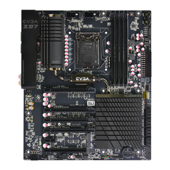
See the picture below for a zoomed in view of a hole to use a standoff in as well as the locations of standoff holes for all boards in the Z97 series. - 4 -... - Page 5 Above, all locations safe to secure the board to a standoff with are circled in red, and the upper left side of that picture is a zoomed in view of the hole. Keep in mind that when the screws are installed but not fully tightened, ...
-
Page 6: Connecting Cables
Connecting Cables This section takes you through all the necessary connections on the motherboard. This will include: Power Connections 24pin ATX power ( EPS 8pin 12V power Internal Headers Front Panel connectors (power/reset/LED’s) Fan Headers (PWM for CPU and DC for ) USB 2.0 Header USB 3.0 Header Audio Header (FTW and Classified) -
Page 7: 8-Pin Atx 12V Power (Pwr 8P1)
Connector Signal Signal +3.3V +3.3V +3.3V -12V PS_ON PWROK RSVD +5V_AUX +12V +12V +3.3V EPS 8-pin 12V Power (PWR , the 8-pin ATX 12V power connections, is used to provide EPS PWR 8P1 power to the CPU. Align the pins to the connector and press firmly until seated. The secondary is optional for improved overclocking. -
Page 8: Connecting Internal Headers
Connecting Internal Headers Front Panel Header The front panel header on this motherboard is used to connect the following four cables. PWRLED Attach the front panel power LED cable to these two pins of the connector. The Power LED indicates the system’s status. When the system is powered on, the LED will be on. -
Page 9: Usb Headers
USB Headers Connector Signal This motherboard contains 5V_DUAL USB 3.0 and 2.0 ports that are USB 2.0 Header Connector exposed on the rear panel of the chassis. The motherboard also contains 10-pin internal header connectors onboard Empty that can be used to connect an Signal optional external bracket 5V_DUAL... -
Page 10: Audio
Audio The audio connector supports HD audio standard and provides two kinds of audio output choices: the Front Audio and the Rear Audio. Connector Signal PORT1_L Front Audio Connector AUD_GND PORT1_R PRECENCE_J PORT2_R SENSE1_RETURN SENSE_SEND Empty PORT2_L SENSE2_RETURN PCI-E x16/x8 Slot This board has a single PCI-E 16x slot. -
Page 11: Onboard Buttons
Onboard Buttons These onboard buttons include RESET, POWER and Clear CMOS. These functions allow you to easily reset the system, turn on/off the system, or clear the CMOS. Clear CMOS Button The motherboard uses the CMOS RAM to store all the set parameters. The CMOS can be cleared by pressing the Clear CMOS button either onboard or on the external I/O Panel. -
Page 12: Post Debug Led And Led Status Indicators
Post Debug LED and LED Status Indicators Post Port Debug LED Provides two-digit diagnostic POST codes which shows system boot status and can also show why the system may be failing to boot. It is very useful during troubleshooting situations. This Debug LED will display a series of hexadecimal (0-F) codes during the POST and upon a successful boot, will display current CPU socket temperatures after the system has fully booted into the Operating System. -
Page 13: Installing Drivers And Software
32bit and 64bit versions of Windows 8 or 7. The kit comes with a CD that contains utilities, drivers, and additional software. The CD that has been shipped with the EVGA Z97 Motherboard contains the following software and drivers: Chipset Drivers ... -
Page 14: Post Codes
POST Codes This section provides the AMI POST Codes for the EVGA Z97 Dark Motherboard during system boot The POST Codes are displayed on the Debug LED readout located directly onboard the motherboard. Debug LED with CPU Temperature Monitor This Debug LED will also display current CPU temperatures after the system has fully booted into the Operating System. - Page 15 information Memory initialization. Configuring memory Memory initialization (other). Reserved for ASL (see ASL Status Codes section below) Memory Installed CPU post-memory initialization is started CPU post-memory initialization. Cache initialization CPU post-memory initialization. Application Processor(s) (AP) initialization CPU post-memory initialization. Boot Strap Processor (BSP) selection CPU post-memory initialization.
- Page 16 Recovery firmware image is found Recovery firmware image is loaded F5-F7 Reserved for future AMI progress codes Recovery PPI is not available Recovery capsule is not found Invalid recovery capsule FB–FF Reserved for future AMI error codes DXE Core is started NVRAM initialization Installation of the South Bridge Runtime Services 63-67...
- Page 17 SCSI Reset SCSI Detect SCSI Enable Setup Verifying Password Start of Setup Reserved for ASL (see ASL Status Codes section below) Setup Input Wait Reserved for ASL (see ASL Status Codes section below) Ready To Boot event Legacy Boot event Exit Boot Services event CPU Memory controller configuration Runtime Set Virtual Address MAP End...
-
Page 18: Evga Glossary Of Terms
DIMM - Dual In-line Memory Module DMI – Direct Memory Interface DRAM - Dynamic random access memory DVI – Digital Video Interface ELEET/ELEET X – EVGA motherboard monitoring and tuning software GHz – Gigahertz GPU – Graphics Processing Unit HDD - Hard Disk Drive HDMI - High-Definition Multimedia Interface HDR –... - Page 19 IRQ - Interrupt Request JBOD - Just a Bunch of Disks JEDEC - Joint Electron Device Engineering Council LAN - Local Area Network LCD - Liquid Crystal Display LGA – Land Grid Array LN2 – Liquid Nitrogen Cooling MAC - Media Access Control MCP - Media and Communications Processor Intel ME –...
- Page 20 SATA - Serial Advanced Technology Attachment SAS – Serial Attached SCSI SB - Southbridge SCSI - Small Computer System Interface SFR – Split Frame Rendering SLI - Scalable Link Interface SPD - Serial Presence Detect S/PDIF - Sony/Philips Digital Interconnect Format SPP - System Platform Processors SSD –...
-
Page 21: Compliance Information
Original Purchaser. Upon termination, for any reason, all copies of Software and materials must be immediately returned to EVGA and the Original Purchaser shall be liable to EVGA.com CORP for any and all damages suffered as a result of the violation or default.