Table of Contents
Advertisement
For U.S.A., Canada, Europe, U.K.,
Australia, Asia, China, Hong Kong,
Taiwan R.O.C. & Korea model
Hi-Fi Component
SERVICE MANUAL
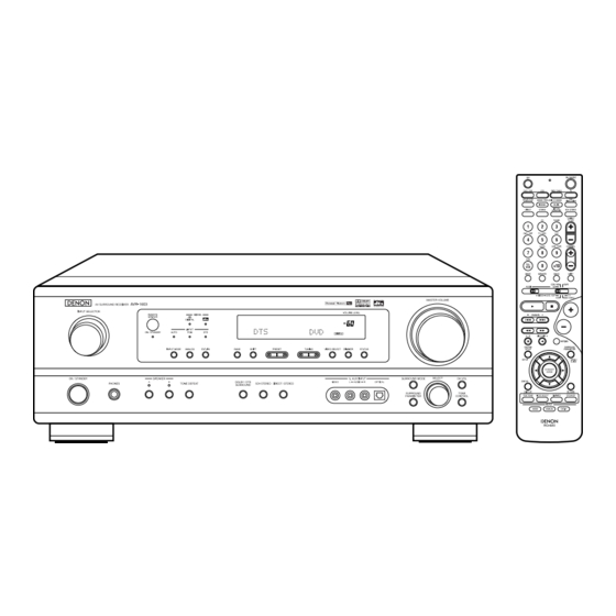
AVR-1603/683
MODEL
AV SURROUND RECEIVER
Some illustrations using in this service manual are slightly different from the actual set.
16-11, YUSHIMA 3-CHOME, BUNKYOU-KU, TOKYO 113-0034 JAPAN
Telephone: 03 (3837) 5321
X0152 NC 0209
Advertisement
Table of Contents

Related Manuals for Denon AVR-1603/683


Summary of Contents for Denon AVR-1603/683
-
Page 1: Service Manual
Australia, Asia, China, Hong Kong, Taiwan R.O.C. & Korea model Hi-Fi Component SERVICE MANUAL AVR-1603/683 MODEL AV SURROUND RECEIVER Some illustrations using in this service manual are slightly different from the actual set. 16-11, YUSHIMA 3-CHOME, BUNKYOU-KU, TOKYO 113-0034 JAPAN... -
Page 2: Safety Precautions
AVR-1603/683 SAFETY PRECAUTIONS The following check should be performed for the continued protection of the customer and service technician. LEAKAGE CURRENT CHECK Before returning the unit to the customer, make sure you make either (1) a leakage current check or (2) a line to chassis resistance check. - Page 3 AVR-1603/683 General Power supply: AC120V, 60Hz (U.S.A. & Canada Models) AC230V, 50Hz (Europe, U.K. & Australia Models) AC115/230V, 50/60Hz (Asia Model) Power consumption: 4.0A (USA & Canada model) 210W (Europe, U.K., Australia & Asia models) 434 (W) × 147 (H) × 417 (D) mm (17-3/32″ × 5-25/32″ × 1-23/64″)
-
Page 4: Top Cover
AVR-1603/683 DISASSEMBLY (Follow the procedure below in the reverse order when reassembling) Top Cover 1. Top Cover Remove 6 screws and 3 screws , then detach the Top Cover to the arrow direction. 2. Front Panel (1) Remove 4 screws... - Page 5 AVR-1603/683 LEVEL DIAGRAMS FRONT/CENTER/SURROUND...
- Page 6 AVR-1603/683 SUB WOOFER...
- Page 7 AVR-1603/683 BLOCK DIAGRAM...
-
Page 8: Tuner Section
AVR-1603/683 ADJUSTMENT Tuner Section CONNECTION DIAGRAM OF MEASURING INSTRUMENTS T402 T403 STEREO R471 MODULATOR IC402 75ohm FM SSG VR402 Digital Voltmeter TUNER B'D FM ALIGNMENT Input Output Adjustment Tuning Alignment Step Frequency Input Item Type Frequency Modulation Coupling Type Connect to... -
Page 9: Audio Section
AVR-1603/683 Audio Section Idling Current Required measurement equipment : DC Voltmeter Preparation (1) Avoid direct blow from an air conditioner or an electric fan, and adjust the unit at normal room tempereture 15 °C ~ 30 °C (59 °F ~ 86 °F). - Page 10 AVR-1603/683 SEMICONDUCTORS IC’s CXP740096 (IC201) PI6/SO1 PI7/SI1 PE0/INT0 PE1/INT2 PE2/PWM0 PE3/PWM1 PB7/SI2 PB6/SO2 PB5/SCK2 PB4/TO2 PG0/TxD PG1/RxD PG2/EC0 PG3/EC1 PG4/EC2 TOP VIEW PG5/INT3 PG6/INT4 PG7/CINT PF0/AN4 PF1/AN5 PF2/AN6 PF3/AN7 PF4/AN8 CXP740096 Terminal Function Pin Name Function 3811K1MUTE BD3811K1 CONTROL 3811K1CLK...
- Page 11 AVR-1603/683 Pin Name Function 24 RELAY F-A FRONT A RELAY 25 RELAY SURR SURROUND RELAY 26 RELAY CNT CENTER RELAY 27 RELAY H/P H/P RELAY 28 FUNC UP ENCODER INPUT(FUNCTION) 29 H/P DETECT H/P DETECT 30 FUNC DOWN ENCODER INPUT(FUNCTION) ...
- Page 12 AVR-1603/683 Pin Name Function 77 PWR DOWN POWER DOWN DETECT 78 RDS CLK TDA7330 CONTROL CLOCK 79 RDS DATA TDA7330 CONTROL DATA 80 NC 81 VIDEO MUTE VIDEO MUTE 82 M32 INTREQ MELODY32 CONTROL 83 VIDEO SEL1 VIDEO SELECT1...
- Page 13 AVR-1603/683 MELODY32 (IC802) TOP VIEW MELODY32 Terminal Function Pin Name Pin Name Pin Name Pin Name Pin Name Pin Name 25 V 49 DR2 73 RESET 97 A11 121 WR DDEXT 26 HACK 50 RCLK2 74 TDO 98 A12 122 RD...
- Page 14 AVR-1603/683 AD1837 (IC808) DVDD DVDD DBCLK CLATCH DLRCLK PD/RST AGND AGND OUTR4 TOP VIEW OUTL1 OUTL4 OUTR1 AGND AGND AVDD AVDD OUTR3 OUTL2 DVDD DVDD ODVDD ALRCLK ABCLK ASDATA CCLK CLATCH COUT MCLK PD/RST M/S AVDD AVDD DLRCLK CONTROL PORT...
- Page 15 AVR-1603/683 LC89057W (IC807) EMPHA/UO AUDIO/VO XMODE Microcontroller RXOUT C bit, U bit 37 DO 36 RERR 24 SDIN 23 SLRCK Input Demodulation 22 SBCK Data Selector 21 RDATA & Selector 21 RDATA Lock Detect XMODE 20 RLRCK RX5/VI DGND 19 DVDD...
- Page 16 AVR-1603/683 Pin Name Function XOUT X’tal osc. connecting output terminal X’tal osc. connection, external clock input terminal (24.576MHz or 12.288MHz) DVDD — Digital power DGND — Digital GND EMPHA/UO Emphasis information/U-data output/Chip address setting terminal AUDIO/VO Non-PCM detect/V-flag output/ Chip address setting terminal...
- Page 17 AVR-1603/683 M29W800AT (IC805) PIN DESCRIPTION Symbol Pin Name BYTE A0-A18 Address Inputs DQ15A-1 DQ0-DQ7 Data Input/Outputs, Command Inputs DQ8-DQ14 Data Input/Outputs DQ14 DQ0-DQ14 A0-A18 DQ15A-1 Data Input/Output or Address Input DQ13 Chip Enable DQ15A-1 DQ12 Output Enable M29W800T BYTE M29W800AT...
- Page 18 AVR-1603/683 LC75721E (IC301) MM74LCX244 (IC809~811) LC75721E Terminal Function TOP VIEW Symbol Function Power terminal +5V Power terminal GND Power terminal FL drive AM 17 Serial data transfer terminal AM 18 DI: Data AM 19 AM 20 CL: Clock AM 21...
- Page 19 AVR-1603/683 BA7625 (IC651) BA7626 (IC652,653) Monitor OUT CTL A V OUT1 LOGIC CTL E CTL B LOGIC V OUT2 CTL D CTL C MONITOR OUT V OUT 1 V OUT 2 IN 1 IN 1 IN 2 IN 2...
- Page 20 AVR-1603/683 TRANSISTORS DTA114ES DTA114EK DTC114TS DTA114YK DTC Series DTA Series DTC114YS DTA144EK DTC144ES DTC114EK DTC114YK DTC144EK FRONT VIEW VIEW DTA114EK 10kohm /Ω 10kohm /Ω 10kohm /Ω 10kohm /Ω DTC114EK DTC114TS 10kohm /Ω DTA114ES 10kohm /Ω 10kohm /Ω DTA114YK 10kohm /Ω 47kohm /Ω...
- Page 21 AVR-1603/683 FL DISPLAY 16-st-42GNK (FL301) TUNED STEREO PHONO TUNER DVD / −1 −2 −3 −1 −2 AUTO V.AUX TAPE MULTI PRO LOGIC DIGITAL DIGITAL ANALOG G2~G16 G12 G10 VDP TV TUNED STEREO PHONO TUNER DVD / / DBS −1 −2 −3 V.AUX −1...
- Page 22 AVR-1603/683 PRINTED WIRING BOARDS MAIN P.W.B. UNIT(for U.S.A., Canada, U.K., Europe, China, Korea & Australia models) COMPONENT SIDE...
- Page 23 AVR-1603/683 MAIN P.W.B. UNIT(for Asia, HongKong, & Taiwan R.O.C. models) COMPONENT SIDE...
- Page 24 AVR-1603/683 CPU P.W.B. UNIT COMPONENT SIDE...
- Page 25 AVR-1603/683 FOIL SIDE...
- Page 26 AVR-1603/683 CNT P.W.B. UNIT COMPONENT SIDE...
- Page 27 AVR-1603/683 FOIL SIDE...
- Page 28 AVR-1603/683 INPUT-VOL P.W.B. UNIT COMPONENT SIDE FOIL SIDE...
- Page 29 AVR-1603/683 DSP P.W.B. UNIT COMPONENT SIDE FOIL SIDE...
- Page 30 AVR-1603/683 VOLTAGE SEL P.W.B. UNIT COMPONENT SIDE...
- Page 31 AVR-1603/683 NOTE FOR PARTS LIST Part indicated with the mark " " are not always in stock and possibly to take a long period of time for supplying, or in some case supplying of part may be refused. When ordering of part, clearly indicate "1" and "I" (i) to avoid mis-supplying.
- Page 32 AVR-1603/683 Note : The symbols in the column “Remarks” indicate the following destinations. E3 : U.S.A. & Canada model E1 : Asia model PARTS LIST OF P.W.B. UNIT ASS'Y EU : U.S.A. model (AVR-683) E1C : China model E2 : Europe model E1H : Hong Kong model EK : U.K.
- Page 33 AVR-1603/683 Ref. No. Part No. Part Name Remarks Ref. No. Part No. Part Name Remarks R107FR 963 0047 900 Metal film 4.7 kohm 1W CAPACITORS GROUP R107SL 963 0047 900 Metal film 4.7 kohm 1W C101C 093 9005 888 Electrolytic 47uF/50V R107SR 963 0047 900 Metal film 4.7 kohm 1W...
- Page 34 AVR-1603/683 Ref. No. Part No. Part Name Remarks Ref. No. Part No. Part Name Remarks Q'ty New C157 963 9005 749 Electrolytic 1uF/50V OTHER PARTS GROUP C158 963 9003 136 Electrolytic 1000uF/25V CN601 963 0086 709 11P connector socket C159...
- Page 35 AVR-1603/683 CPU P.W.B. ASS'Y Ref. No. Part No. Part Name Remarks Q'ty New Ref. No. Part No. Part Name Remarks Heat sink reg TR SEMICONDUCTORS GROUP Heat sink IC201 963 0095 800 IC CXP740096-156Q 963 0094 924 Mini trans...
- Page 36 AVR-1603/683 Ref. No. Part No. Part Name Remarks Ref. No. Part No. Part Name Remarks RESISTORS GROUP RP06 963 9004 397 Carbon chip 56 kohm 1/16W RP07 963 9004 397 Carbon chip 56 kohm 1/16W R202 963 9003 398 Carbon chip 1 kohm 1/16W...
- Page 37 AVR-1603/683 Ref. No. Part No. Part Name Remarks Ref. No. Part No. Part Name Remarks Q'ty OTHER PARTS GROUP C262 963 9004 575 Ceramic chip 100pF/50V BD201,202 963 0053 800 Beads inductor C263 963 9004 575 Ceramic chip 100pF/50V C264...
- Page 38 AVR-1603/683 CNT P.W.B. ASS'Y Ref. No. Part No. Part Name Remarks Ref. No. Part No. Part Name Remarks SEMICONDUCTORS GROUP Q626 960 0005 202 Transistor KTC3198Y Q627 960 0196 904 Transistor DTC114YS IC401 963 0043 700 IC LC72131-PLL Q628 960 0196 904 Transistor DTC114YS...
- Page 39 AVR-1603/683 Ref. No. Part No. Part Name Remarks Ref. No. Part No. Part Name Remarks R414 963 9004 216 Carbon chip 2.2 kohm 1/16W R481FR 963 9004 245 Carbon chip 2.2 Mohm 1/16W R415 963 9003 398 Carbon chip 1 kohm 1/16W R481SL 963 9004 245 Carbon chip 2.2 Mohm 1/16W...
- Page 40 AVR-1603/683 Ref. No. Part No. Part Name Remarks Ref. No. Part No. Part Name Remarks CAPACITORS GROUP 963 9005 448 Ceramic 330pF/50V for E2,EK,EA 963 9004 931 Ceramic 180pF/50V for E1,E1C,E1H,E1K,E1T C341 963 9004 546 Ceramic 0.01uF/16V C448 963 9004 960 Ceramic 470pF/50V...
- Page 41 AVR-1603/683 Ref. No. Part No. Part Name Remarks Ref. No. Part No. Part Name Remarks C506SL 963 9005 312 Electrolytic 100uF/10V C691 963 9005 749 Electrolytic 1uF/50V C506SR 963 9005 312 Electrolytic 100uF/10V C692 963 9005 749 Electrolytic 1uF/50V C507C 963 9003 194 Mylar film 0.0022uF/100V...
- Page 42 AVR-1603/683 INPUT VOLUME P.W.B. ASS'Y Ref. No. Part No. Part Name Remarks Q'ty Ref. No. Part No. Part Name Remarks SW901 960 0176 209 Push SW for E3,EU SEMICONDUCTORS GROUP IC701 963 0096 401 IC BD3811K1 T401 960 0186 600 If MW coil PCFMAF-270...
- Page 43 AVR-1603/683 Ref. No. Part No. Part Name Remarks Ref. No. Part No. Part Name Remarks R712L 963 9004 245 Carbon chip 2.2 Mohm 1/16W R763SW 963 9004 834 Carbon chip 5.6 kohm 1/16W R712R 963 9004 245 Carbon chip 2.2 Mohm 1/16W R764FL 963 9004 410 Carbon chip 6.2 kohm 1/16W...
- Page 44 AVR-1603/683 Ref. No. Part No. Part Name Remarks Ref. No. Part No. Part Name Remarks CAPACITORS GROUP C762FR 963 9004 575 Ceramic chip 100pF/50V C762SW 963 9004 575 Ceramic chip 100pF/50V C701L 963 9004 575 Ceramic chip 100pF/50V for E2,EK,EA C763FL 963 9004 753 Ceramic chip 0.047uF/50V...
- Page 45 AVR-1603/683 DSP P.W.B. ASS'Y Ref. No. Part No. Part Name Remarks Ref. No. Part No. Part Name Remarks SEMICONDUCTORS GROUP R863L 963 9004 339 Carbon chip 470 ohm 1/16W R863R 963 9004 339 Carbon chip 470 ohm 1/16W IC802 963 0084 905 IC GP1FA502RZ...
- Page 46 AVR-1603/683 Ref. No. Part No. Part Name Remarks Ref. No. Part No. Part Name Remarks R922 963 9004 342 Carbon chip 4.7 kohm 1/16W R996 963 9004 326 Carbon chip 47 ohm 1/16W R923 963 9004 410 Carbon chip 6.2 kohm 1/16W...
- Page 47 AVR-1603/683 Ref. No. Part No. Part Name Remarks Ref. No. Part No. Part Name Remarks C823 963 9005 752 Electrolytic 10uF/35V C873SW 963 9004 672 Ceramic chip 680pF/50V C825 963 9005 749 Electrolytic 1uF/50V C874 963 9004 698 Ceramic chip 0.01uF/50V...
- Page 48 AVR-1603/683 VOLTAGE SEL. P.W.B. ASS’Y (for Asia, Hong Kong & Taiwan R.O.C. model only) Ref. No. Part No. Part Name Remarks Ref. No. Part No. Part Name Remarks Q'ty C962 963 9004 708 Ceramic chip 0.1uF/50V OTHER PARTS GROUP (E1,G1H,G1T model only) C965 963 9004 708 Ceramic chip 0.1uF/50V...
- Page 49 AVR-1603/683 EXPLODED VIEW WARNING: Parts marked with this symbol have critical characteristics. Use ONLY replacement parts recommended by the manufacturer. 38 -1...
- Page 50 E1,E1T,E1H 963 0093 048 Front Panel for E1,E1C,E1T, E1H,E1K 963 0092 049 for E1C 2 963 0051 501 DENON Badge for black model 963 0092 052 for E1K 963 0051 514 DENON Badge for gold model 3 963 0093 116 Window for E3,EU,E1,E1C,E1T,E1H,E1K 1 Main P.W.B.
- Page 51 AVR-1603/683 Ref. No. Part No. Part Name Remarks Q'ty Ref. No. Part No. Part Name Remarks Q'ty 34 963 0074 009 8P Pin Jack SCREWS 35 960 0158 308 Push SW Block A 963 0018 007 Screw,Tap Tite 3x8 B-Type Zny/Bh for E3,EU,E2,EK,EA 44...
- Page 52 AVR-1603/683 PACKING VIEW * POLY BAG PACKING STYLE TAPE(CLEAR) S E T CORD AC Note : The symbols in the column “Remarks” indicate the following destinations. E3 : U.S.A. & Canada model E1 : Asia model EU : U.S.A. model (AVR-683)
- Page 53 AVR-1603/683 WIRING DIAGRAM...
-
Page 54: Schematic Diagrams
AVR-1603/683 SCHEMATIC DIAGRAMS (1/8) NOTICE: ALL RESISTANCE VALUES IN OHM. k=1,000 OHM M=1,000,000 OHM CAUTION: ALL CAPACITANCE VALUES IN MICRO FARAD. P=MICRO-MICRO FARAD B LINE Before returning the unit to the customer, make sure you make either (1) a EACH VOLTAGE AND CURRENT ARE MEASUERD AT NO SIGNAL INPUT leakage current check or (2) a line to chassis resistance check. - Page 55 AVR-1603/683 SCHEMATIC DIAGRAMS (1/8) NOTICE: ALL RESISTANCE VALUES IN OHM. k=1,000 OHM M=1,000,000 OHM CAUTION: ALL CAPACITANCE VALUES IN MICRO FARAD. P=MICRO-MICRO FARAD B LINE Before returning the unit to the customer, make sure you make either (1) a EACH VOLTAGE AND CURRENT ARE MEASUERD AT NO SIGNAL INPUT leakage current check or (2) a line to chassis resistance check.
- Page 56 SCHEMATIC DIAGRAMS (1/8)
- Page 57 NOTICE: ALL RESISTANCE VALUES IN OHM. k=1,000 OHM M=1,000,000 OHM CAUTION: ALL CAPACITANCE VALUES IN MICRO FARAD. P=MICRO-MICRO FARAD Before returning the unit to the customer, make sure you make either (1) a EACH VOLTAGE AND CURRENT ARE MEASUERD AT NO SIGNAL INPUT leakage current check or (2) a line to chassis resistance check.
- Page 58 AVR-1603/683...
- Page 59 B LINE SIGNAL LINE SCHEMATIC DIAGRAMS (1/8) INPUT-VOL UNIT...
- Page 60 AVR-1603/683 SCHEMATIC DIAGRAMS (2/8) NOTICE: ALL RESISTANCE VALUES IN OHM. k=1,000 OHM M=1,000,000 OHM WARNING: ALL CAPACITANCE VALUES IN MICRO FARAD. P=MICRO-MICRO FARAD Parts marked with this symbol have critical characteristics. B LINE EACH VOLTAGE AND CURRENT ARE MEASUERD AT NO SIGNAL INPUT Use ONLY replacement parts recommended by the manufacture.
- Page 61 AVR-1603/683 SCHEMATIC DIAGRAMS (2/8) NOTICE: ALL RESISTANCE VALUES IN OHM. k=1,000 OHM M=1,000,000 OHM WARNING: ALL CAPACITANCE VALUES IN MICRO FARAD. P=MICRO-MICRO FARAD Parts marked with this symbol have critical characteristics. B LINE EACH VOLTAGE AND CURRENT ARE MEASUERD AT NO SIGNAL INPUT Use ONLY replacement parts recommended by the manufacture.
- Page 62 SCHEMATIC DIAGRAMS (2/8)
- Page 63 NOTICE: ALL RESISTANCE VALUES IN OHM. k=1,000 OHM ALL CAPACITANCE VALUES IN MICRO FARAD. P= EACH VOLTAGE AND CURRENT ARE MEASUERD CONDITION. CIRCUIT AND PARTS ARE SUBJECT TO CHANGE NOTICE. WARNING: DO NOT return the unit to the customer until the pro corrected.
- Page 64 AVR-1603/683...
- Page 65 000 OHM M=1,000,000 OHM WARNING: ARAD. P=MICRO-MICRO FARAD Parts marked with this symbol have critical characteristics. B LINE ASUERD AT NO SIGNAL INPUT Use ONLY replacement parts recommended by the manufacture. SIGNAL LINE CAUTION: CHANGE WITHOUT PRIOR Before returning the unit to the customer, make sure you make either (1) a leakage current check or (2) a line to chassis resistance check.
- Page 66 AVR-1603/683 SCHEMATIC DIAGRAMS (3/8) B LINE NOTICE: ALL RESISTANCE VALUES IN OHM. k=1,000 OHM M=1,000,000 OHM SIGNAL LINE CAUTION: ALL CAPACITANCE VALUES IN MICRO FARAD. P=MICRO-MICRO FARAD Before returning the unit to the customer, make sure you make either (1) a EACH VOLTAGE AND CURRENT ARE MEASUERD AT NO SIGNAL INPUT CONDITION.
- Page 67 AVR-1603/683 SCHEMATIC DIAGRAMS (3/8) NOTICE: B LINE ALL RESISTANCE VALUES IN OHM. k=1,000 OHM M=1,000,000 OHM SIGNAL LINE CAUTION: ALL CAPACITANCE VALUES IN MICRO FARAD. P=MICRO-MICRO FARAD Before returning the unit to the customer, make sure you make either (1) a EACH VOLTAGE AND CURRENT ARE MEASUERD AT NO SIGNAL INPUT CONDITION.
- Page 68 SCHEMATIC DIAGRAMS (3/8)
- Page 69 NOTIC ALL RE ALL CA EACH V CONDIT CIRCUI NOTICE WARN Parts m Use ON...
- Page 70 AVR-1603/683...
- Page 71 B LINE NOTICE: ALL RESISTANCE VALUES IN OHM. k=1,000 OHM M=1,000,000 OHM SIGNAL LINE CAUTION: ALL CAPACITANCE VALUES IN MICRO FARAD. P=MICRO-MICRO FARAD Before returning the unit to the customer, make sure you make either (1) a EACH VOLTAGE AND CURRENT ARE MEASUERD AT NO SIGNAL INPUT leakage current check or (2) a line to chassis resistance check.
- Page 72 AVR-1603/683 SCHEMATIC DIAGRAMS (4/8) B LINE SIGNAL LINE NOTICE: WARNING: WARNING: ALL RESISTANCE VALUES IN OHM. k=1,000 OHM M=1,000,000 OHM Parts marked with this symbol have critical characteristics. DO NOT return the unit to the customer until the problem is located and ALL CAPACITANCE VALUES IN MICRO FARAD.
- Page 73 AVR-1603/683 SCHEMATIC DIAGRAMS (4/8) B LINE SIGNAL LINE NOTICE: WARNING: WARNING: ALL RESISTANCE VALUES IN OHM. k=1,000 OHM M=1,000,000 OHM Parts marked with this symbol have critical characteristics. DO NOT return the unit to the customer until the problem is located and ALL CAPACITANCE VALUES IN MICRO FARAD.
- Page 74 SCHEMATIC DIAGRAMS (4/8)
- Page 75 NOTICE: WARNING: WARNING: ALL RESISTANCE VALUES IN OHM. k=1,000 OHM M=1,000,000 OHM Parts marked with this symbol have critical characteristics. DO NOT return ALL CAPACITANCE VALUES IN MICRO FARAD. P=MICRO-MICRO FARAD Use ONLY replacement parts recommended by the manufacture. corrected. EACH VOLTAGE AND CURRENT ARE MEASUERD AT NO SIGNAL INPUT CAUTION: CONDITION.
- Page 76 AVR-1603/683...
- Page 77 B LINE SIGNAL LINE RNING: OT return the unit to the customer until the problem is located and SCHEMATIC DIAGRAMS (4/8) cted. MAIN UNIT OUTLET UNIT VOLTAGE SEL UNIT...
- Page 78 AVR-1603/683 SCHEMATIC DIAGRAMS (5/8) WARNING: B LINE Parts marked with this symbol have critical characteristics. SIGNAL LINE Use ONLY replacement parts recommended by the manufacture. CAUTION: Before returning the unit to the customer, make sure you make either (1) a NOTICE: leakage current check or (2) a line to chassis resistance check.
- Page 79 AVR-1603/683 SCHEMATIC DIAGRAMS (5/8) WARNING: B LINE Parts marked with this symbol have critical characteristics. SIGNAL LINE Use ONLY replacement parts recommended by the manufacture. CAUTION: Before returning the unit to the customer, make sure you make either (1) a NOTICE: leakage current check or (2) a line to chassis resistance check.
- Page 80 SCHEMATIC DIAGRAMS (5/8)
- Page 82 AVR-1603/683...
- Page 83 WARNING: B LINE Parts marked with this symbol have critical characteristics. SIGNAL LINE Use ONLY replacement parts recommended by the manufacture. CAUTION: Before returning the unit to the customer, make sure you make either (1) a NOTICE: leakage current check or (2) a line to chassis resistance check. If the leakage ALL RESISTANCE VALUES IN OHM.
- Page 84 AVR-1603/683 SCHEMATIC DIAGRAMS (6/8) NOTICE: ALL RESISTANCE VALUES IN OHM. k=1,000 OHM M=1,000,000 OHM ALL CAPACITANCE VALUES IN MICRO FARAD. P=MICRO-MICRO FARAD EACH VOLTAGE AND CURRENT ARE MEASUERD AT NO SIGNAL INPUT CONDITION. CIRCUIT AND PARTS ARE SUBJECT TO CHANGE WITHOUT PRIOR NOTICE.
- Page 85 AVR-1603/683 SCHEMATIC DIAGRAMS (6/8) NOTICE: ALL RESISTANCE VALUES IN OHM. k=1,000 OHM M=1,000,000 OHM ALL CAPACITANCE VALUES IN MICRO FARAD. P=MICRO-MICRO FARAD EACH VOLTAGE AND CURRENT ARE MEASUERD AT NO SIGNAL INPUT CONDITION. CIRCUIT AND PARTS ARE SUBJECT TO CHANGE WITHOUT PRIOR NOTICE.
- Page 86 SCHEMATIC DIAGRAMS (6/8)
- Page 88 AVR-1603/683...
- Page 89 NOTICE: ALL RESISTANCE VALUES IN OHM. k=1,000 OHM M=1,000,000 OHM ALL CAPACITANCE VALUES IN MICRO FARAD. P=MICRO-MICRO FARAD EACH VOLTAGE AND CURRENT ARE MEASUERD AT NO SIGNAL INPUT CONDITION. CIRCUIT AND PARTS ARE SUBJECT TO CHANGE WITHOUT PRIOR NOTICE. WARNING: B LINE SCHEMATIC DIAGRAMS (6/8) Parts marked with this symbol...
- Page 90 AVR-1603/683 SCHEMATIC DIAGRAMS (7/8) B LINE SCHEMATIC DIAGRAMS (7/8) SIGNAL LINE NOTICE: FRONT UNIT WARNING: WARNING: ALL RESISTANCE VALUES IN OHM. k=1,000 OHM M=1,000,000 OHM Parts marked with this symbol have critical characteristics. DO NOT return the unit to the customer until the problem is located and OPTICAL-IN UNIT ALL CAPACITANCE VALUES IN MICRO FARAD.
- Page 91 AVR-1603/683 SCHEMATIC DIAGRAMS (7/8) B LINE SCHEMATIC DIAGRAMS (7/8) SIGNAL LINE FRONT UNIT NOTICE: WARNING: WARNING: ALL RESISTANCE VALUES IN OHM. k=1,000 OHM M=1,000,000 OHM Parts marked with this symbol have critical characteristics. DO NOT return the unit to the customer until the problem is located and OPTICAL-IN UNIT ALL CAPACITANCE VALUES IN MICRO FARAD.
- Page 92 SCHEMATIC DIAGRAMS (7/8)
- Page 93 NOTICE: WARNING: WARNING: ALL RESISTANCE VALUES IN OHM. k=1,000 OHM M=1,000,000 OHM Parts marked with this symbol have critical characteristics. DO NOT return the unit to the cu ALL CAPACITANCE VALUES IN MICRO FARAD. P=MICRO-MICRO FARAD Use ONLY replacement parts recommended by the manufacture. corrected.
- Page 94 AVR-1603/683...
- Page 95 B LINE SCHEMATIC DIAGRAMS (7/8) SIGNAL LINE FRONT UNIT OPTICAL-IN UNIT to the customer until the problem is located and POWER-SW UNIT ENCODER UNIT HEADPHONE UNIT...
- Page 96 AVR-1603/683 SCHEMATIC DIAGRAMS (8/8) B LINE NOTICE: WARNING: WARNING: SIGNAL LINE Parts marked with this symbol have critical characteristics. ALL RESISTANCE VALUES IN OHM. k=1,000 OHM M=1,000,000 OHM DO NOT return the unit to the customer until the problem is located and ALL CAPACITANCE VALUES IN MICRO FARAD.
- Page 97 AVR-1603/683 SCHEMATIC DIAGRAMS (8/8) B LINE SIGNAL LINE NOTICE: WARNING: WARNING: Parts marked with this symbol have critical characteristics. ALL RESISTANCE VALUES IN OHM. k=1,000 OHM M=1,000,000 OHM DO NOT return the unit to the customer until the problem is located and ALL CAPACITANCE VALUES IN MICRO FARAD.
- Page 98 SCHEMATIC DIAGRAMS (8/8)
- Page 99 NOTICE: WARNING: WARNING: Parts marked with this symbol have critical characteristics. ALL RESISTANCE VALUES IN OHM. k=1,000 OHM M=1,000,000 OHM DO NOT return the unit to th ALL CAPACITANCE VALUES IN MICRO FARAD. P=MICRO-MICRO FARAD Use ONLY replacement parts recommended by the manufacture. corrected.
- Page 100 AVR-1603/683...
- Page 101 B LINE SIGNAL LINE unit to the customer until the problem is located and SCHEMATIC DIAGRAMS (8/8) TUNER UNIT...