
Related Manuals for Sony TRINITRON KV-PG14P70


Summary of Contents for Sony TRINITRON KV-PG14P70
-
Page 1: Service Manual
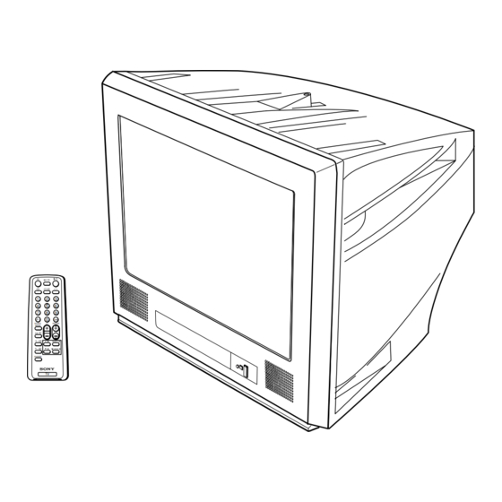
SERVICE MANUAL BG2T CHASSIS MODEL COMMANDER DEST. CHASSIS NO. MODEL COMMANDER DEST. CHASSIS NO. KV-PG14P70 RM-952 SCC-U68C-A ÷ JUMP Á SOUND PROGR MODE FAVORITE TRINITRON COLOR TV ®... - Page 2 THE PARTS LIST ARE CRITICAL TO SAFE OPERATION. OR CARBON PAINTED ON THE CRT, AFTER REMOVING THE REPLACE THESE COMPONENTS WITH SONY PARTS ANODE. WHOSE PART NUMBERS APPEAR AS SHOWN IN THIS MANUAL OR IN SUPPLEMENTS PUBLISHED BY SONY. – 2 –...
-
Page 3: Table Of Contents
KV-PG14M40/PG14M72/L/N KV-PG14P42/G/L/N/PG14P70 RM-952 TABLE OF CONTENTS Section Title Page Section Title Page SELF DIAGNOSTIC FUNCTION ........4 5. DIAGRAMS 5-1. Block Diagram ............27 1. GENERAL ..............7 5-2. Circuit Boards Location .......... 29 5-3. Schematic Diagram ..........30 2. DISASSEMBLY (1) Schematic Diagram of A Board ...... -
Page 4: Self Diagnostic Function
KV-PG14M40/PG14M72/L/N KV-PG14P42/G/L/N/PG14P70 RM-952 SELF DIAGNOSTIC FUNCTION The units in this manual contain a self-diagnostic function. If an error occurs, the STANDBY/TIMER lamp will automati- cally begin to flash. The number of times the lamp flashes translates to a probable source of the problem. A definition of the STANDBY/ TIMER lamp flash indicators is listed in the instruction manual for the user’s knowledge and reference. - Page 5 KV-PG14M40/PG14M72/L/N KV-PG14P42/G/L/N/PG14P70 RM-952 2. DISPLAY OF STANDBY/TIMER LIGHT FLASH COUNT Diagnostic Item Flash Count* 2 times +B overcurrent/overvoltage 2 times Vertical deflection stopped 4 times 4 times * One flash count is not used for self-diagnostic. Lamp ON 0.3 sec. Lamp OFF 3 sec.
- Page 6 KV-PG14M40/PG14M72/L/N KV-PG14P42/G/L/N/PG14P70 RM-952 5. HANDLING OF SELF-DIAGNOSTIC SCREEN DISPLAY Since the diagnostic results displayed on the screen are not automatically cleared, always check the self-diagnostic screen during repairs. When you have completed the repairs, clear the result display to “0”. Unless the result display is cleared to “0”, the self-diagnostic function will not be able to detect subsequent faults after completion of the repairs.
- Page 7 KV-PG14M40/PG14M72/L/N KV-PG14P42/G/L/N/PG14P70 RM-952 Getting Started WARNING (KV-PG14M40/PG14P70/PG14M72/ PG14M72/N/L) • Dangerously high voltages are present inside the TV. Step 1 • TV operating voltage: 220 – 240 V AC. (KV-PG14M72/PG14P42) 110 – 240 V AC. (KV-PG14M40/PG14P70) Insert the batteries (supplied) into the remote. •...
-
Page 8: Tv Front And Rear Panels
TV. Remote control sensor. • Count the number of times the 1 (standby) indicator flashes. Press ! The 1 (standby) (main power) to turn off your TV. Contact your nearest Sony service indicator on your TV Standby indicator. center. -
Page 9: Setting The Timers
KV-PG14M40/PG14M72/L/N KV-PG14P42/G/L/N/PG14P70 RM-952 Presetting channels (continued) (KV-PG14M40/PG14M72) Setting the timers You can turn on and off your TV by using the buttons respectively. To change the TV system setting If the picture or sound is abnormal when receiving programs through the 8 (antenna) Setting the Wake Up timer terminal Press... -
Page 10: Customizing The Picture And Sound
KV-PG14M40/PG14M72/L/N KV-PG14P42/G/L/N/PG14P70 RM-952 Customizing the picture and sound Enjoying stereo or bilingual You can customize the picture and sound by selecting the picture and sound programs (KV-PG14M72/PG14M72/N/L) modes or by adjusting its settings. You can enjoy stereo sound or bilingual programs of NICAM and A2 stereo Selecting the picture mode systems by using the A/B button. -
Page 14: Set-Up Adjustments
KV-PG14M40/PG14M72/L/N KV-PG14P42/G/L/N/PG14P70 SECTION 3 RM-952 SET-UP ADJUSTMENTS The following adjustments should be made when a complete Perform the adjustments in the following order : realignment is required or a new picture tube is installed. 1. Beam Landing These adjustments should be performed with rated power 2. -
Page 15: Convergence
KV-PG14M40/PG14M72/L/N KV-PG14P42/G/L/N/PG14P70 RM-952 3-2. CONVERGENCE • Operation of V. Stat magnet If the V. Stat magnet is moved in the "a" and "b" arrows, the Preparation : red, green and blue dots move as shown below. • Before starting this adjustment, adjust the focus, horizontal size and vertical size. - Page 16 KV-PG14M40/PG14M72/L/N KV-PG14P42/G/L/N/PG14P70 RM-952 (2) Dynamic Convergence Adjustment Preparation: Before starting this adjustment, adjust the horizontal static convergence and the vertical static convergence Insert Correction Plate to DY Pocket (Left or Right) YCH Rotate YCH VOL on DY Rotate TLV VOL ON DY XCV Rotate XCV Adj core on DY ON DY: DY pocket...
-
Page 17: Focus Adjustment
KV-PG14M40/PG14M72/L/N KV-PG14P42/G/L/N/PG14P70 RM-952 3-4. G2 (SCREEN) AND WHITE BALANCE (3) Screen-corner Convergence ADJUSTMENTS G2 (SCREEN) ADJUSTMENT 1) Set the PICTURE to normal. a-d : screen-corner 2) Put to VIDEO input mode without signals. misconvergence 3) Connect R, G and B of the C board cathode to the oscilloscope. -
Page 18: Circuit Adjustments
KV-PG14M40/PG14M72/L/N KV-PG14P42/G/L/N/PG14P70 SECTION 4 RM-952 CIRCUIT ADJUSTMENTS 4-1. ADJUSTMENT WITH COMMANDER 4-2. ADJUSTMENT METHOD Service adjustments to this model can be performed using the Item Number 00 HPS supplied Remote Commander RM-952 This explanation uses H Shift as an example. 1. - Page 21 KV-PG14M72/N KV-PG14P42 KV-PG14P42/G KV-PG14P42/L KV-PG14P42/N KV-PG14P70 Switch-on behaviour 1 = Switch-on of picture via unternal delay 0 = Without delay 00(4) 1 = Switch-off in vertical overscan 0 = Switch-off undefind 18(7) Service blanking 1 = on 0 = off...
- Page 22 KV-PG14M72 KV-PG14M72/L KV-PG14M72/N KV-PG14P42 KV-PG14P42/G KV-PG14P42/L KV-PG14P42/N KV-PG14P70 HA ME Vol Tone controller Volume curve setting. 1 = for HA(ME), 0 = for HA(GE) AV Input 00 = no AV Input model 01 = 1 AV Input model 10 = 2 AV Input model...
- Page 23 KV-PG14M72 KV-PG14M72/L KV-PG14M72/N KV-PG14P42 KV-PG14P42/G KV-PG14P42/L KV-PG14P42/N KV-PG14P70 No Bal. 1 = no balance in analog select items, 0 = balance included (for AV stereo model) SPC SOUND 1 = Space Sound available, 0 = not available Korean ST (Reserved for NTSC model) H.K.
-
Page 24: Picture Quality Adjustment
KV-PG14M40/PG14M72/L/N KV-PG14P42/G/L/N/PG14P70 RM-952 4-3. PICTURE QUALITY ADJUSTMENT 4-4. DEFLECTION ADJUSTMENT NORMAL MODE (50Hz) SUB COLOR ADJUSTMENT Set to Service mode. 1. Select Video. Input PAL color bar. Using the 1 and 4 button, select category GEO 2. Input a PAL color-bar. 3. -
Page 25: Picture Distortion Adjustment
KV-PG14M40/PG14M72/L/N KV-PG14P42/G/L/N/PG14P70 RM-952 4-6. PICTURE DISTORTION ADJUSTMENT Item Number 00 – 08 HPS (H POSITION) HSZ (H SIZE) PAP (PIN AMPLITUDE) CPN (CORNER PIN) TLT (TILT) VSL (V SLOPE) VAP (VERTICAL AMPLITUDE) SCO (S CORRECTION) VPS (V SHIFT) – 25 –... -
Page 26: Diagrams
KV-PG14M40/PG14M72/L/N KV-PG14M40/PG14M72/L/N KV-PG14P42/G/L/N/PG14P70 KV-PG14P42/G/L/N/PG14P70 SECTION 5 RM-952 RM-952 DIAGRAMS 5-1. BLOCK DIAGRAM POWER SUPPLY, DEFLECTION, C (RGB OUTPUT) Q405 J1201 AUDIO & VIDEO PROCESSING, BUFFER VIDEO AUDIO/VIDEO INPUT/OUTPUT AND MICROCOMPUTER MONITOR Q712 Q706 L (MONO) Q407, 406 R DRIVE R AMP VIDEO BUFFER VIDEO... -
Page 27: Circuit Boards Location
KV-PG14M40/PG14M72/L/N KV-PG14M40/PG14M72/L/N KV-PG14P42/G/L/N/PG14P70 KV-PG14P42/G/L/N/PG14P70 RM-952 RM-952 5-3. SCHEMATIC DIAGRAM 5-2. CIRCUIT BOARDS LOCATION Note: • All capacitors are in µF unless otherwise noted. • All electrolytic capacitors are rated at 50V unless otherwise noted. • All resistors are in ohms. kΩ... -
Page 28: Schematic Diagram Of A Board
KV-PG14M40/PG14M72/L/N KV-PG14M40/PG14M72/L/N KV-PG14P42/G/L/N/PG14P70 KV-PG14P42/G/L/N/PG14P70 RM-952 RM-952 (1) Schematic Diagram of A Board CN300 CN302 CN301 CN200 FOR C J200 TO A3 BOARD JACK D200 L200 C426 DA204K C418 C113 R102 R438 SWF100 TP300 R928 R991 Q202 R225 JW020 TU100 R101 FILTER SURFACE WAVE R921 R922... -
Page 29: Schematic Diagram Of C And F Boards
KV-PG14M40/PG14M72/L/N KV-PG14M40/PG14M72/L/N KV-PG14P42/G/L/N/PG14P70 KV-PG14P42/G/L/N/PG14P70 RM-952 RM-952 (2) Schematic Diagrams of C and F Boards CN702 :TAB (RGB OUTPUT) TO G2-FBT L701 22UH :EL0607 200V R703 C701 100k 0.0047 C704 1/2W 0.022 FOCUS 400V R705 G1-1 J701 0.47 SOCKET CN701 H.STAT :S-MICRO G1-2 G1-3... -
Page 30: Schematic Diagram Of A3 Board
KV-PG14M40/PG14M72/L/N KV-PG14M40/PG14M72/L/N KV-PG14P42/G/L/N/PG14P70 KV-PG14P42/G/L/N/PG14P70 RM-952 RM-952 (3) Schematic Diagram of A3 Board (STEREO DECODER) IC2201 C2204 C2203 IC2701 SIF DETECTOR 0.01 F:K2 R2207 US STEREO DECODER 2NDSIF FMDET 2.2k C2211 1/10W C2705 0.01 L-RREF BIASFIL FMFIL F:K2 C2714 R2202 MIXOUT 1STSIF WBTIME R2206... - Page 31 KV-PG14M40/PG14M72/L/N KV-PG14M40/PG14M72/L/N KV-PG14P42/G/L/N/PG14P70 KV-PG14P42/G/L/N/PG14P70 RM-952 RM-952 A Board ✼ Mark List A Board ✼ Mark List A Board ✼ Mark List KV-PG14M40 KV-PG14P42 KV-PG14P70 KV-PG14M72 KV-PG14M40 KV-PG14P42 KV-PG14P70 KV-PG14M72 KV-PG14M40 KV-PG14P42 KV-PG14P70 KV-PG14M72 KV-PG14P42/G KV-PG14M72/L KV-PG14P42/G KV-PG14M72/L KV-PG14P42/G KV-PG14M72/L KV-PG14P42/N...
-
Page 32: Voltage Measurement
KV-PG14M40/PG14M72/L/N KV-PG14P42/G/L/N/PG14P70 RM-952 5-4. VOLTAGE MEASUREMENT A(1/2) BOARD VOLTAGE LIST Pin No Voltage[v] Pin No Voltage[v] Pin No Voltage[v] IC001 13.4 (3.4) [3.9] (0) [5.0] IC004 (2.4) [2.1] (0) [0.2] IC101 IC201 (0) [5.0] (5.0) [0] (0) [0.3] (*) [0.6] (4.0) [4.3] (4.2) [4.0] (4.6) [1.1]... - Page 33 KV-PG14M40/PG14M72/L/N KV-PG14P42/G/L/N/PG14P70 RM-952 A(2/2) BOARD VOLTAGE LIST Pin No Voltage[v] Pin No Voltage[v] Pin No Voltage[v] IC601 Q106 Q313 (45.5) [0.4] (8.7) [0.4] Q201 (0.4) [4.7] Q314 (0.2) [0] IC602 121.9 Q204 16.5 Q315 16.5 IC604 13.4 15.8 Q205 (4.8) [0.2] Q318 (0) [0.2] (0.4) [5.4]...
-
Page 34: Waveforms
KV-PG14M40/PG14M72/L/N KV-PG14P42/G/L/N/PG14P70 RM-952 C BOARD VOLTAGE LIST Pin No Voltage[v] J701 (260.4) [258.4] (120) [125] (117) [119] Q705 (8.3) [124.4] (8.3) [0.3] Q710 Q711 Q704 (121.7) [123.2] (8.3) [6.3] Q706 (8.3) [6] Q707 (122) [125.2] (120) [125.2] Q708 (120.7) [123.4] (118.2) [124.3] Q709 (119) [120.1]... -
Page 35: Printed Wiring Boards And Parts Location
KV-PG14M40/PG14M72/L/N KV-PG14P42/G/L/N/PG14P70 RM-952 5-6. PRINTED WIRING BOARDS AND PARTS LOCATION PRINTED WIRING BOARDS [RGB OUTPUT] [CISPR] [STEREO DECODER] – C Board – – A3 Board – (KV-PG14M72/PG14M72/L/N only) – F Board – (KV-PG14M72/PG14M72/L/N only) CN4603 R2309 C2403 C2203 Q2303 X2401 Q2301 C4602 D2302... - Page 36 KV-PG14M40/PG14M72/L/N KV-PG14M40/PG14M72/L/N KV-PG14P42/G/L/N/PG14P70 KV-PG14P42/G/L/N/PG14P70 RM-952 RM-952 PRINTED WIRING BOARDS [POWER SUPPLY,DEFLECTION,AUDIO AND VIDEO PROCESSING, NOTE: AUDIO/VIDEO INPUT/OUTPUT AND MICROCOMPUTER] The circuit indicated at left contains high voltage of over 1220 Vp-p. Please pay attention when inspecting or re- pairing it to prevent an electric shock. –...
-
Page 37: Semiconductors
KV-PG14M40/PG14M72/L/N KV-PG14M40/PG14M72/L/N KV-PG14P42/G/L/N/PG14P70 KV-PG14P42/G/L/N/PG14P70 RM-952 RM-952 5-7. SEMICONDUCTORS DIODE CATHODE MARKING SIDE VIEW CATHODE ANODE ANODE (GRN) TOP VIEW CATHODE ANODE CATHODE (GRN) ANODE ANODE Small Outline L-Leaded Zig-zag In -line Package Pin 8~98 Pin 6~99 D1NL20U NNCD8.2A-T1 RD5.6ESB2 RD2.2ES-B2 SPB-25MVWF DA204K ELIZ... -
Page 38: Exploded Views
KV-PG14M40/PG14M72/L/N KV-PG14P42/G/L/N/PG14P70 RM-952 SECTION 6 EXPLODED VIEWS NOTE: • • Items marked " ∗ " are not stocked since Items with no part number and no The components identified by description are not stocked because they are seldom required for routine shading and mark ! are critical they are seldom required for routine ser vice. - Page 39 X-4039-480-1 DOOR ASSY, CONTROL (KV-PG14M72) * A-1299-632-A A BOARD COMPLETE X-4039-713-1 DOOR ASSY, CONTROL (KV-PG14P42) (KV-PG14P42/PG14P42/L/G/N) X-4039-715-1 DOOR ASSY, CONTROL (KV-PG14P42(G)) * A-1299-614-A A BOARD COMPLETE (KV-PG14P70) X-4039-714-1 DOOR ASSY, CONTROL (KV-PG14P42(L)) ! 1-453-309-21 TRANSFORMER ASSY FLYBACK X-4039-716-1 DOOR ASSY, CONTROL (KV-PG14P42(N))
-
Page 40: Electrical Parts List
0.1UF * A-1299-637-A A BOARD COMPLETE (KV-PG14M40/PG14P70/PG14M72/L/N) (KV-PG14M72/PG14M72/L/PG14M72/N) C036 1-164-360-11 CERAMIC CHIP 0.1UF * A-1299-632-A A BOARD COMPLETE (KV-PG14P42/ (KV-PG14P42/G/L/N) PG14P42/G/PG14P42/L/PG14P42/N) * A-1299-614-A A BOARD COMPLETE (KV-PG14P70) C037 1-162-927-11 CERAMIC CHIP 100PF 5.00% ******************** C038 1-162-927-11 CERAMIC CHIP 100PF 5.00%... - Page 41 KV-PG14M40/PG14M72/L/N KV-PG14P42/G/L/N/PG14P70 The components identified by shading RM-952 and mark ! are critical for safety. Replace only with part number specified. REF NO. PART NO. DESCRIPTION REMARK REF NO. PART NO. DESCRIPTION REMARK C105 1-164-360-11 CERAMIC CHIP 0.1UF C300 1-162-923-11 CERAMIC CHIP 47PF 5.00%...
- Page 42 KV-PG14M40/PG14M72/L/N KV-PG14P42/G/L/N/PG14P70 The components identified by shading RM-952 and mark ! are critical for safety. Replace only with part number specified. REF NO. PART NO. DESCRIPTION REMARK REF NO. PART NO. DESCRIPTION REMARK C339 1-163-038-91 CERAMIC CHIP 0.1UF C414 1-164-360-11 CERAMIC CHIP 0.1UF (KV-PG14M40/PG14P70/PG14M72/L/N)
- Page 43 KV-PG14M40/PG14M72/L/N KV-PG14P42/G/L/N/PG14P70 The components identified by shading RM-952 and mark ! are critical for safety. Replace only with part number specified. REF NO. PART NO. DESCRIPTION REMARK REF NO. PART NO. DESCRIPTION REMARK C803 1-102-244-00 CERAMIC 220PF 10.00% 500V C804 1-162-318-11 CERAMIC 0.001UF 10.00% 500V...
- Page 44 RD13SB2 JR100 1-216-864-11 SHORT (KV-PG14P42/G/L/N/PG14P70) JR212 1-216-295-91 SHORT <CONNECTOR> JR214 1-216-295-91 SHORT JR300 1-216-295-91 SHORT 0 (KV-PG14P70) * 1-580-798-11 CONNECTOR PIN (DY) 6P JR301 1-216-295-91 SHORT (KV-PG14M40/PG14M72/L/N) <FUSE> JR304 1-216-295-91 SHORT F600 ! 1-576-016-11 FUSE, TIME-LAG (BET) 3.15A/250V <COIL> (KV-PG14M40/PG14P42/G/L/N/PG14P70)
- Page 45 KV-PG14M40/PG14M72/L/N KV-PG14P42/G/L/N/PG14P70 The components identified by shading RM-952 and mark ! are critical for safety. Replace only with part number specified. REF NO. PART NO. DESCRIPTION REMARK REF NO. PART NO. DESCRIPTION REMARK Q801 8-729-055-74 TRANSISTOR 2SD2624-CA L400 1-414-187-11 INDUCTOR 47UH Q802 8-729-050-48...
- Page 46 KV-PG14M40/PG14M72/L/N KV-PG14P42/G/L/N/PG14P70 The components identified by shading RM-952 and mark ! are critical for safety. Replace only with part number specified. REF NO. PART NO. DESCRIPTION REMARK REF NO. PART NO. DESCRIPTION REMARK R206 1-216-824-11 RES-CHIP 1.8K 1/16W R059 1-216-033-00 RES-CHIP 1/10W (KV-PG14M40/PG14P42/G/L/N/PG14P70)
- Page 47 KV-PG14M40/PG14M72/L/N KV-PG14P42/G/L/N/PG14P70 The components identified by shading RM-952 and mark ! are critical for safety. Replace only with part number specified. REF NO. PART NO. DESCRIPTION REMARK REF NO. PART NO. DESCRIPTION REMARK (KV-PG14M40/PG14M72/L/N) R391 1-208-822-11 METAL CHIP 0.5% 1/10W R326 1-216-081-00 RES-CHIP...
- Page 48 KV-PG14M40/PG14M72/L/N KV-PG14P42/G/L/N/PG14P70 The components identified by shading RM-952 and mark ! are critical for safety. Replace only with part number specified. REF NO. PART NO. DESCRIPTION REMARK REF NO. PART NO. DESCRIPTION REMARK (KV-PG14M40/PG14P70) S004 1-692-431-21 SWITCH, TACTILE R605 1-207-615-00 METAL 0.33 S005...
- Page 49 KV-PG14M40/PG14M72/L/N KV-PG14P42/G/L/N/PG14P70 The components identified by shading RM-952 and mark ! are critical for safety. Replace only with part number specified. REF NO. PART NO. DESCRIPTION REMARK REF NO. PART NO. DESCRIPTION REMARK C2208 1-163-009-91 CERAMIC CHIP 0.001UF 10.00% 50V FB2406 1-414-231-22 FERRITE...
- Page 50 KV-PG14M40/PG14M72/L/N KV-PG14P42/G/L/N/PG14P70 The components identified by shading RM-952 and mark ! are critical for safety. Replace only with part number specified. REF NO. PART NO. DESCRIPTION REMARK REF NO. PART NO. DESCRIPTION REMARK <FILTER> <JACK> SF2101 1-795-295-11 FILTER, SAW (38MHZ) J701 ! 1-540-071-22 SOCKET, CRT...
- Page 51 1-418-861-32 REMOTE COMMANDER (RM-952) (KV-PG14P42/G) ACCESSORIES AND PACKING MATERIALS 4-084-290-01 BATTERY COVER, REMOTE COMMANDER *************************************** (KV-PG14M40/PG14M72/PG14M72/N/ PG14P70/PG14P42/PG14P42/N) 1-569-008-11 ADAPTOR, CONVERSION 2P (KV-PG14P70) 4-075-331-11 BATTERY COVER, REMOTE COMMANDER 1-417-151-22 MATCHING TRANSFORMER, ANTENNA (KV-PG14M72/L/PG14P42/L) (KV-PG14P70/PG14P42/L/G/N) 4-075-331-31 BATTERY COVER, REMOTE COMMANDER 1-501-372-81 ANTENNA, TELESCOPIC...
- Page 52 (CHAMPAGNE GOLD) (GREY) KV-PG14M72/N RM-952 Hong Kong SCC-U64D-A KV-PG14P70 RM-952 SCC-U68C-A (CHAMPAGNE GOLD) (GREY) KV-PG14P42 KV-PG14P70 RM-952 Thailand SCC-U73B-A RM-952 Indonesia SCC-U68C-A (COOL SILVER) (GREY) Sony Corporation Sony Technology Malaysia Sdn. Bhd. English 9-872-269-02 Visual Products 2002.3 – 61 –...