Table of Contents
Advertisement
Advertisement
Table of Contents

Related Manuals for Honeywell PCR-100


Summary of Contents for Honeywell PCR-100
- Page 1 PCR-100 PCR-110 Installation and Operating Instructions Electronic thermostat...
-
Page 2: Table Of Contents
TABLE OF CONTENTS 11 Unpacking the unit and conditions of use 12 General instructions 13 Use and function 3.1 Use for the purpose intended 3.2 Function 14 Safety 4.1 Sources of danger 4.2 Safety precautions 15 Installation and commissioning 5.1 Mechanical installation 5.2 Electrical installation 16 Operation of the controller 6.1 Switching on the operating voltage... -
Page 3: Unpacking The Unit And Conditions Of Use
1 Unpacking the unit and conditions of use Before and when unpacking the unit, make a visual inspection to identify any possible damage which may have occurred during trans- portation. Please look for loose parts, dents, scratches, etc. Report any damage immediately to the freight company. (Please see “Conditions if damage has occurred”.) In other instances, the latest edition of the “General conditions for the supply of goods and services”... -
Page 4: Function
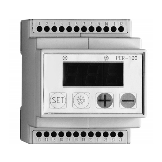
Please take the application limits into account (see Technical Data in section 11). 3.2 Function PCR-100 and PCR-110 are general-purpose thermostats, each with a relay output and wide temperature control range (–55 °C to +50 °C). The controllers have different housings: PCR-100: Modular housing for 35 mm standard rails PCR-110: “Snap-in”... -
Page 5: Safety Precautions
If the unit cannot be operated without the risk of danger, it must be taken out of service and precautions taken so that it cannot be switched on again unintentionally. This applies, in particular, if: the housing has damage which is visible, the unit is no longer operational or it has been stored for a long time in unfavourable conditions. -
Page 6: Electrical Installation
Snap – in housings: Fit the unit in an aperture 28,5 x 70,5 mm and secure it with the relevant mounting frame. a) housings with terminal box coverplate (max. wall thickness 22 mm) b) housings without terminal box cover plate (max. -
Page 7: Operation Of The Controller
Instructions: For PCR-110 the total current via terminal 5 of the common relay connection must not exceed 10 A. Pay attention to the contact loading of the relay (8A/5A resistive load, 2A/1A inductive load). As a general rule, contactors are recommended. -
Page 8: Switching On The Operating Voltage
6.1 Switching on the operating voltage The controller is started by means of a control switch provided by the customer. The first time the controller is started, pre-programmed setting values are used which at a later point can be adapted for individual require- ments. -
Page 9: Adjusting The Cold Store Temperature
Input values are always changed using the key held down. Input parameters, e.g. the switching difference is shown as “E” with a 2-digit number, e.g. “E 01”. Access to the programming level is by pressing the key at the same time for 5 seconds. The parameters to be changed can then be accessed by pressing keys. -
Page 10: Input Parameters And Ranges
7.1 Input parameters and input ranges: Parameter on display E00 Cold store temperature difference E01 Min. permissible cold store temp. E02 Max. permissible cold store temp. E03 Delay time, relay energizing E04 Alarm temperature difference If the set temperature difference E04 is negative, an alarm is given if it is too cold in the refrigerated area, e.g. -
Page 11: Sensor Calibration (Parameter E06)
If the time interval between two defrost cycles is changed when the system is in operation, the new time interval will not be applied until after the next time defrosting has occurred. E09 Defrost time (0 = no defrosting) E10 Max. display delay after defrosting During the defrosting process, the last current tempe- rature before defrosting started is retained in the dis-... -
Page 12: Maintenance
If the measured temperature is higher than the one displayed, set the positive difference as the programming value (e.g. 2K). The temperature display is then corrected by the set value. 8 Maintenance The controller does not require any maintenance. It does not have any fuses so, if brief voltage spikes occur, the refrigeration system will not stop operating for a prolonged period. -
Page 13: Conditions Of Warranty
10 Conditions of warranty Warranty is provided for a period of 24 months, starting at the date the item was delivered. Proof of this should be furnished in the form of a delivery note or invoice. All functional faults caused by poor workmanship or faulty materials will be repaired free of charge during the warranty period. - Page 14 –30 °C to +80 °C not fixed –40 °C to +80 °C fixed ±2 % PCR-100: L x W x H = 85 x 70 x 61 mm PCR-110: L x W x H = 70 x 74 x 32 mm ABS plastic, self-extinguishing...
- Page 15 Full technical documentation is available. Operating instructions for the device are provided. Mosbach, March 22 , 1999 i.V. Dr. Osthues R & D / Production Manager as defined in the and the FLICA, Electronic thermostat PRC-100, PCR-110 Honeywell Flica Honeywell AG Hardhofweg D-74821 Mosbach...
- Page 16 +49 (0) 62 61 / 81-475 Fax: +49 (0) 62 61 / 81-461 E-Mail: Cooling.Mosbach@honeywell.com www.honeywell-cooling.com Manufactured for and on behalf of the Environment and Combustion Controls Division of Honeywell Technologies Sàrl, Ecublens, Route du Bois 37, Switzerland by its autorised representative Honeywell GmbH...