Table of Contents

Related Manuals for Sony Trinitron KV-TG21M61


Summary of Contents for Sony Trinitron KV-TG21M61
-
Page 1: Service Manual
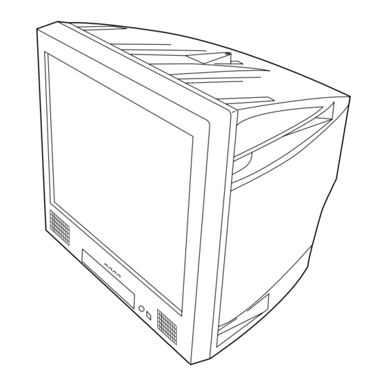
SERVICE MANUAL BG-2T CHASSIS MODEL COMMANDER DEST. CHASSIS NO. MODEL COMMANDER DEST. CHASSIS NO. KV-TG21M61 RM-952 Singapore SCC-U66B-A KV-TG21M90 RM-952 Hong Kong SCC-U64A-A ÷ JUMP SOUND Á PROGR MODE FAVORITE TRINITRON COLOR TV ®... - Page 2 THE PARTS LIST ARE CRITICAL TO SAFE OPERATION. OR CARBON PAINTED ON THE CRT, AFTER REMOVING THE REPLACE THESE COMPONENTS WITH SONY PARTS ANODE. WHOSE PART NUMBERS APPEAR AS SHOWN IN THIS MANUAL OR IN SUPPLEMENTS PUBLISHED BY SONY. – 2 –...
-
Page 3: Table Of Contents
KV-TG21M61/TG21M90 RM-952 TABLE OF CONTENTS Section Title Page Section Title Page SELF DIAGNOSTIC FUNCTION ........4 5. DIAGRAMS 1. GENERAL ..............7 5-1. Block Diagram ............25 5-2. Circuit Boards Location .......... 27 2. DISASSEMBLY 5-3. Schematic Diagram ..........28 2-1. -
Page 4: Self Diagnostic Function
KV-TG21M61/TG21M90 RM-952 SELF DIAGNOSTIC FUNCTION The units in this manual contain a self-diagnostic function. If an error occurs, the STANDBY/TIMER lamp will automati- cally begin to flash. The number of times the lamp flashes translates to a probable source of the problem. A definition of the STANDBY/ TIMER lamp flash indicators is listed in the instruction manual for the user’s knowledge and reference. - Page 5 KV-TG21M61/TG21M90 RM-952 2. DISPLAY OF STANDBY/TIMER LIGHT FLASH COUNT Diagnostic Item Flash Count* 2 times +B overcurrent/overvoltage 2 times Vertical deflection stopped 4 times 4 times * One flash count is not used for self-diagnostic. Lamp ON 0.3 sec. Lamp OFF 3 sec.
- Page 6 KV-TG21M61/TG21M90 RM-952 5. HANDLING OF SELF-DIAGNOSTIC SCREEN DISPLAY Since the diagnostic results displayed on the screen are not automatically cleared, always check the self-diagnostic screen during repairs. When you have completed the repairs, clear the result display to “0”. Unless the result display is cleared to “0”, the self-diagnostic function will not be able to detect subsequent faults after completion of the repairs.
-
Page 7: Getting Started
KV-TG21M61/TG21M90 RM-952 WARNING (continued) Getting Started Step 1 Insert the batteries (supplied) into the remote. Pull the power cord out by the plug. Do not pull the power cord itself. Even if your TV is turned Note off, it is still connected to the AC power source •... -
Page 8: Specifications
• Count the number of times the 1 (standby) indicator flashes. Press ! (red, green, Access a FASTEXT The 1 (standby) (main power) to turn off your TV. Contact your nearest Sony service indicator on your TV yellow, blue) menu. -
Page 9: Setting The Timers
KV-TG21M61/TG21M90 RM-952 Presetting channels (continued) Setting the timers You can turn on and off your TV by using the buttons respectively. To change the TV system setting If the picture or sound is abnormal when receiving programs through the 8 (antenna) -
Page 10: Adjusting The Picture Position
KV-TG21M61/TG21M90 RM-952 Viewing Teletext Adjusting the picture position If the picture is slanting, you can adjust the picture position using the Not function for your TV “PIC ROTATION” function until it is optimal. Some TV stations broadcast an information service called Teletext which... -
Page 13: Set-Up Adjustments
KV-TG21M61/TG21M90 RM-952 SECTION 3 SET-UP ADJUSTMENTS The following adjustments should be made when a complete Perform the adjustments in the following order : realignment is required or a new picture tube is installed. 1. Beam Landing These adjustments should be performed with rated power 2. -
Page 14: Convergence
KV-TG21M61/TG21M90 RM-952 3-2. CONVERGENCE • Operation of V. Stat magnet If the V. Stat magnet is moved in the "a" and "b" arrows, the Preparation : red, green and blue dots move as shown below. • Before starting this adjustment, adjust the focus, horizontal size and vertical size. - Page 15 KV-TG21M61/TG21M90 RM-952 (2) Dynamic Convergence Adjustment Preparation: Before starting this adjustment, adjust the horizontal static convergence and the vertical static convergence Insert Correction Plate to DY Pocket (Left or Right) YCH Rotate YCH VOL on DY Rotate TLV VOL ON DY...
-
Page 16: Focus Adjustment
KV-TG21M61/TG21M90 RM-952 3-4. G2 (SCREEN) AND WHITE BALANCE (3) Screen-corner Convergence ADJUSTMENTS G2 (SCREEN) ADJUSTMENT 1) Set the PICTURE to normal. a-d : screen-corner 2) Put to VIDEO input mode without signals. misconvergence 3) Connect R, G and B of the CV board cathode to the oscilloscope. -
Page 17: Circuit Adjustments
KV-TG21M61/TG21M90 RM-952 SECTION 4 CIRCUIT ADJUSTMENTS 4-1. ADJUSTMENT WITH COMMANDER e. OTHER FUNCTION VIA REMOTE COMMANDER 7, - All the data becomes the values in memory. Service adjustments to this model can be performed using the 8, - All user control goes to the standard state. - Page 20 KV-TG21M61/TG21M90 RM-952 ITEM INFORMATION No. 1E VP1 Item KV-TG21M61 KV-TG21M90 Switch-on behaviour 1=Switch -on of picture via internal delay 0=Without delay 00(4) 1=Switch off in vertical overscan 0=Switch-off undefind 18(7) Service blanking Mode 1= on 0= off 0B(7) RGB Blanking Mode 1 = wide blanking, 0 = normal blanking...
- Page 21 KV-TG21M61/TG21M90 RM-952 No. 4F OP2 Item No NICAM US ST HDEV 1 V-Curve XTAL SEL SECAM 2nd Lang. KV-TG21M61 KV-TG21M90 No NICAM 1 = NICAM search is disable in any TV system, 0 = NICAM search operates US ST (Reserved for NTSC model)
-
Page 22: Picture Quality Adjustment
KV-TG21M61/TG21M90 RM-952 4-3. PICTURE QUALITY ADJUSTMENT 4-4. DEFLECTION ADJUSTMENT NORMAL MODE (50Hz) SUB COLOR ADJUSTMENT Set to Service mode. 1. Select Video. Input PAL color bar. Using the 1 and 4 button, select category GEO 2. Input a PAL color-bar. -
Page 23: Picture Distortion Adjustment
KV-TG21M61/TG21M90 RM-952 4-6. PICTURE DISTORTION ADJUSTMENT Item Number 00 – 08 HPS (H POSITION) HSZ (H SIZE) PAP (PIN AMPLITUDE) CPN (CORNER PIN) TLT (TILT) VSL (V SLOPE) VAP (V AMPLITUDE) SCO (S CORRECTION) VPS (V SHIFT) – 23 –... - Page 24 KV-TG21M61/TG21M90 RM-952 MEMO – 24 –...
-
Page 25: Diagrams
IC551 RESET 43 RESET EHTX-RAY V OUT DY ASS'Y X IN X OUT IC5802 Q561 D591 D561 +5V REG +13V X RAY +135V CN002 X801 12MHz CVBS VIDEO CN5803 V2 (TELE TEXT) (KV-TG21M61 ONLY) – 25 – – 26 –... -
Page 26: Circuit Boards Location
• All voltage are in Volt. V2 BOARD ✽ • : Cannot be measured. • Circled numbers are waveform references. (KV-TG21M61 only) • : B +bus. • : B –bus. ÷ • : signal path. Reference information RESISTOR... -
Page 27: Schematic Diagram Of A Board
KV-TG21M61/TG21M90 KV-TG21M61/TG21M90 RM-952 RM-952 (1) Schematic Diagram of A Board TO SPEAKER CN301 CN300 CN302 CN200 J200 TO A3 BOARD TO CV BOARD JACK CN2101 TO A3 BOARD CN703 CN2102 R102 D200 C113 R446 C411 # C201 C418 R437 R438 R101 4.7K... - Page 28 KV-TG21M61/TG21M90 KV-TG21M61/TG21M90 RM-952 RM-952 TO PAGE 1/2 R051 :CHIP IC001 CXP85224A-079S C007 SYSTEM C025 0.001 L001 R057 CONTROLLER C015 C053 R340 B:CHIP R034 0.001 R033 470 10V C005 6.3V R071 0.01 FLR50 C032 :CHIP B:CHIP 200V F:CHIP F:CHIP 0.001 R350 D323 0.0015...
-
Page 29: Schematic Diagram Of A3 Board
KV-TG21M61/TG21M90 KV-TG21M61/TG21M90 RM-952 RM-952 (2) Schematic Diagram of A3 Board (STEREO DECODER) IC2201 C2203 C2204 LA7567BM IC2701 SIF DECODER 0.01 F:CHIP R2207 US STEREO DECODER 2NDSIF FMDET 2.2K C2714 # C2211 BIASFIL FMFIL L-RREF C2705 # 0.01 F:CHIP WBTIME MIXOUT... -
Page 30: Schematic Diagram Of V2 Board
KV-TG21M61/TG21M90 KV-TG21M61/TG21M90 RM-952 RM-952 (3) Schematic Diagram of V2 Board (KV-TG21M61 only) (TELE TEXT) IC5801 SAA5264PS/M3 D5801 # D5802 DAP202K TEXT DECODER C5828 # R5831 4.7K :CHIP C5825 P2.0/PWM P1.5 P2.1/PWM0 P1.4 R5830 4.7K :CHIP C5835 P2.2/PWM1 R5829 100 :CHIP P2.3/PWM2... -
Page 31: Schematic Diagram Of Cv Board
KV-TG21M61/TG21M90 RM-952 (4) Schematic Diagram of CV Board CN702 1P :TAB L701 RGB AMPLIFIER 22UH 200V :EL0607 200V C704 0.022 C701 R703 400V 0.0047 FOCUS 100k 1/2W G1-1 J701 SOCKET R705 CN701 RV702 110M :S-MICRO G1-2 TO A BOARD G1-3... -
Page 32: Schematic Diagram Of F Board
KV-TG21M61/TG21M90 RM-952 (5) Schematic Diagram of F Board (KV-TG21M90 ONLY) CISPR CN4601 VDR461 JW4602 F 4601 T 3.15A ERZV14D621 T 4601 250V AC IN AC OUT JW4601 R4601 AC IN AC OUT 1/2W CN4602 TO A BOARD C4601 T 4602... -
Page 33: Voltage Measurement
KV-TG21M61/TG21M90 RM-952 5-4. VOLTAGE MEASUREMENT A(1/2) BOARD VOLTAGE LIST Pin No Voltage[v] Pin No Voltage[v] Pin No Voltage[v] IC001 (15.5) [0] (4.9) [0] IC003 PH600 (0) [4.8] 17.5 (4.9) [0] IC301 (4.9) [0] (4.9) [1.0] IC004 (3.0) [1.5] IC101 (0.3) [0] IC203 (3.8) [3.3]... - Page 34 KV-TG21M61/TG21M90 RM-952 A(2/2) BOARD VOLTAGE LIST Pin No Voltage[v] Pin No Voltage[v] Pin No Voltage[v] IC551 Q303 Q409 13.3 (12.1) [0] 13.3 Q304 Q500 133.5 (1.2) [0.3] 13.5 133.5 Q307 (2.9) [1.5] Q800 SWF100 51.6 (2.3) [0.9] Q308 Q801 Q001...
- Page 35 KV-TG21M61/TG21M90 RM-952 CV BOARD VOLTAGE LIST A3 BOARD VOLTAGE LIST Pin No Voltage[v] Pin No Voltage[v] Pin No Voltage[v] IC2401 IC2701 J701 (135) [142] G1-1 G1-2 (125) [145] G1-3 Q705 (144) [148] Q704 Q706 (128) [132] Q707 Q708 (143) [146]...
- Page 36 KV-TG21M61/TG21M90 RM-952 V2 BOARD VOLTAGE LIST (KV-TG21M61 ONLY) Pin No Voltage[v] Pin No Voltage[v] IC5801 Q5801 Q5803 Q5805 Q5810 – 42 –...
-
Page 37: Waveforms
KV-TG21M61/TG21M90 RM-952 5-5. WAVEFORMS A BOARD WAVEFORM NTSC3.58 NTSC3.58 NTSC3.58 5.84Vp-p 3.76Vp-p 4.96Vp-p 720mV 3.84Vp-p 4.08Vp-p NTSC3.58 NTSC3.58 NTSC3.58 1.4Vp-p 520Vp-p 1.2Vp-p 1.2Vp-p 1.64Vp-p 1.2Vp-p NTSC3.58 NTSC3.58 NTSC3.58 1.2Vp-p 640mV 3.32Vp-p 1.12Vp-p 3.16Vp-p 2.56Vp-p NTSC3.58 NTSC3.58 NTSC3.58 3.2Vp-p 2.64Vp-p 3.2Vp-p 2.92Vp-p... -
Page 38: Printed Wiring Boards And Parts Location
KV-TG21M61/TG21M90 RM-952 5-6. PRINTED WIRING BOARDS AND PARTS LOCATION PRINTED WIRING BOARDS [CISPR] [STEREO DECODER] – F Board – (KV-TG21M90 only) CN4603 C4602 CN4601 EY4618 EY4614 EY4610 EY4606 JW 4602 JW 4601 JW 4604 EY4620 EY4616 EY4612 EY4608 JW 4603 –... - Page 39 KV-TG21M61/TG21M90 KV-TG21M61/TG21M90 RM-952 RM-952 PRINTED WIRING BOARDS [POWER SUPPLY,DEFLECTION, NOTE: AUDIO AND VIDEO PROCESSING, The circuit indicated at left contains high voltage of over AUDIO/VIDEO INPUT/OUTPUT AND MICROCOMPUTER] 600 Vp-p. Please pay attention when inspecting or repair- ing it to prevent an electric shock.
-
Page 40: Semiconductors
2SA1091-0 UPC574J EY708 2SC3311A-QRS7A R1782 CN707 JW 715 CN702 C701 C1764 JW 702 C1761 CN701 CLP704 CLP703 CN704 – V2 Board – (KV-TG21M61 only) MSD601-RT1 2SA1162-G 2SC3209LK 2SD2624-CA IRF614-005 2SC3779C MSB709-RT1 2SC2712-YG UN2211 2SC1623-L5L6 UN2213 UN2216 JW 5810 C5829 Q5810... - Page 41 KV-TG21M61/TG21M90 RM-952 TOP VIEW TOP VIEW Dual In-line Package Small Outline L-Leaded Pin 6~98 Pin 8~98 MM1319AFBE (7 PIN) M24C08-BN6 (A) (8 PIN) AN5276 LA7567BM UPC455852 (8 PIN) M5216P NJM2903M (8 PIN) NJM4S56AD CXP85224A-079S (64 PIN) TDA743BD013TR PQ09RD11 TDA8844 – 49 –...
-
Page 42: Exploded Views
SPEAKER (9 x 5CM) ( r 4 SCREWS) X-4039-380-1 DOOR ASSY CONTROL (KV-TG21M61) X-4039-302-1 DOOR ASSY CONTROL (KV-TG21M90) 4-051-736-42 PIECE (90) CONV, CORRECT * A-1299-612-A A BOARD COMPLETE (KV-TG21M61) ! 8-738-812-05 PICTURE TUBE (A51LPT70X) (KV-TG21M61) A-1299-570-A A BOARD COMPLETE (KV-TG21M90) ! 8-738-809-05... -
Page 43: Electrical Parts List
When indicating par ts by reference noted. number, please include the board name. REF NO. PART NO. DESCRIPTION REMARK REF NO. PART NO. DESCRIPTION REMARK * A-1299-612-A A BOARD COMPLETE (KV-TG21M61) C038 1-162-927-11 CERAMIC CHIP 100PF 5.00% * A-1299-570-A A BOARD COMPLETE (KV-TG21M90) C039 1-163-038-91 CERAMIC CHIP 0.1UF... - Page 44 0.1UF C418 1-126-933-11 ELECT 100UF 20.00% 16V C300 1-162-925-11 CERAMIC CHIP 68PF 5.00% C425 1-162-927-11 CERAMIC CHIP 100PF 5.00% (KV-TG21M61 0NLY) C426 1-162-927-11 CERAMIC CHIP 100PF 5.00% C301 1-162-920-11 CERAMIC CHIP 27PF 5.00% C500 1-126-933-11 ELECT 100UF 20.00% 16V C302...
- Page 45 1SS355TE-17 C860 1-208-834-11 METAL CHIP 150K 0.5% 1/10W D203 8-719-988-61 1SS355TE-17 C861 1-130-202-00 FILM 0.022UF 5.00% 400V D301 8-719-988-61 1SS355TE-17 (KV-TG21M61 ONLY) D304 8-719-063-66 HZS361-TE C863 1-216-295-91 SHORT D305 8-719-988-61 1SS355TE-17 C865 1-126-933-11 ELECT 100UF 20.00% 16V C866 1-162-974-11 CERAMIC CHIP 0.01UF...
- Page 46 S3L20UF4 JR001 1-216-295-91 SHORT D603 8-719-110-39 RD15ES-B1 JR003 1-216-295-91 SHORT JR006 1-216-295-91 SHORT D604 8-719-063-70 D1NL20U JR007 1-216-295-91 SHORT 0 (KV-TG21M61 ONLY) D605 8-719-063-70 D1NL20U JR013 1-216-295-91 SHORT D606 8-719-063-70 D1NL20U D607 8-719-027-22 D3S6M-F JR014 1-216-295-91 SHORT D608 8-719-312-10 RU4AM-T3...
- Page 47 8-729-424-67 UN2216 R043 1-216-025-11 RES-CHIP 1/10W Q314 8-729-421-22 UN2211 Q315 8-729-010-25 MSD601-RT1 R044 1-216-033-00 RES-CHIP 1/10W Q319 8-729-010-25 MSD601-RT1 (KV-TG21M61 ONLY) R045 1-216-073-91 RES-CHIP 1/10W R046 1-208-816-11 METAL CHIP 0.5% 1/10W Q320 8-729-421-22 UN2211 R047 1-216-025-11 RES-CHIP 1/10W Q400 8-729-010-05...
- Page 48 R371 1-208-820-11 METAL CHIP 0.5% 1/10W R303 1-216-033-00 RES-CHIP 1/10W R374 1-216-057-00 RES-CHIP 2.2K 1/10W R304 1-216-049-11 RES-CHIP 1/10W ( KV-TG21M61 ONLY) R376 1-216-295-91 SHORT R377 1-216-025-11 RES-CHIP 1/10W R305 1-216-045-00 RES-CHIP 1/10W (KV-TG21M61 ONLY) R306 1-216-039-00 RES-CHIP 1/10W R378...
- Page 49 REF NO. PART NO. DESCRIPTION REMARK REF NO. PART NO. DESCRIPTION REMARK R379 1-216-057-00 RES-CHIP 2.2K 1/10W R510 1-260-127-11 CARBON 220K 1/2W (KV-TG21M61 ONLY) R511 1-215-449-00 METAL 1/4W R381 1-216-295-91 SHORT R512 1-215-453-00 METAL 1/4W R384 1-216-025-11 RES-CHIP 1/10W R513...
- Page 50 TU100 8-598-591-00 TUNER, VSS BT-AG402 C2419 1-117-720-11 CERAMIC CHIP 4.7UF C2501 1-164-505-11 CERAMIC CHIP 2.2UF C2502 1-164-505-11 CERAMIC CHIP 2.2UF <VARISTOR> C2601 1-163-038-91 CERAMIC CHIP 0.1UF VDR600 1-803-830-11 VARISTOR (ERZV14D621) C2602 1-163-038-91 CERAMIC CHIP 0.1UF (KV-TG21M61 ONLY) – 58 –...
- Page 51 KV-TG21M61/TG21M90 RM-952 The components identified by shading and mark ! are critical for safety. Replace only with part number specified. REF NO. PART NO. DESCRIPTION REMARK REF NO. PART NO. DESCRIPTION REMARK C2603 1-126-947-11 ELECT 47UF 20.00% 25V R2204 1-216-029-00...
- Page 52 KV-TG21M61/TG21M90 RM-952 The components identified by shading and mark ! are critical for safety. Replace only with part number specified. CV F (KV-TG21M90 ONLY) REF NO. PART NO. DESCRIPTION REMARK REF NO. PART NO. DESCRIPTION REMARK C717 1-102-852-91 CERAMIC 47PF 5.00%...
- Page 53 ! are critical for safety. Replace only with part number specified. (KV-TG21M61 ONLY) REF NO. PART NO. DESCRIPTION REMARK REF NO. PART NO. DESCRIPTION REMARK * A-1342-630-A V2 BOARD MOUNTED (KV-TG21M61) <TRANSISTOR> ********************* Q5801 8-729-230-49 2SC2712-YG Q5803 8-729-230-49 2SC2712-YG...
- Page 54 ! are critical for safety. Replace only with part number specified. REF NO. PART NO. DESCRIPTION REMARK REF NO. PART NO. DESCRIPTION REMARK Sony Corporation Sony Technology Malaysia Sdn. Bhd. English 9-872-259-01 Visual Products General Area 2001.7 – 62 –...