
Related Manuals for JBL PSW-D112


Summary of Contents for JBL PSW-D112
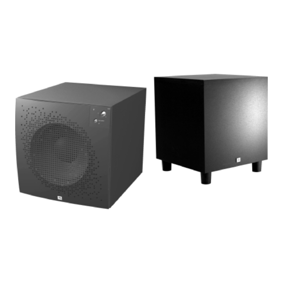
- Page 1 PSW-D112/DPS-12 Powered Subwoofer SERVICE MANUAL JBL Consumer Products Inc. 250 Crossways Park Drive Woodbury, N.Y. 11797 1-800-336-4JBL in the USA A Harman International Company Rev E 7/2001...
-
Page 2: Safety Information
IMPORTANT SERVICE NOTES: When testing the PSW-D112/DPS-12 Series amplifier, a load must always be connected to the output terminals, whether the woofer, or a 4 to 8 ohm resistive load. -
Page 3: Table Of Contents
MECHANICAL PARTS LIST..........19 NOTE: CERTAIN DRAWINGS AND CONNECTIONS WERE DEPICTED INCORRECTLY IN SOME EARLY COPIES OF THE PSW-D112 AND DPS-12 OWNER'S MANUALS . THEY INCLUDE: 1. DRAWING OF RCA LINE LEVEL INPUT/OUTPUT JACKS ON PAGES 3, 4, & 5; ALL CHANNELS - RIGHT SIDE SHOULD BE “LINE OUT”, LEFT SIDE SHOULD BE “LINE IN”. -
Page 4: Detailed Specifications
Amplifier/Subwoofer PSW-D112/DPS-12 DETAILED SPECIFICATIONS LINE VOLTAGE Yes/No Hi/Lo Line Nom. Unit Notes US 120vac/60Hz 108-132 Vrms Normal Operation EU 230vac/50-60Hz 207-264 Vrms Normal operation, MOMS required Parameter Specification Unit Test Limits Conditions Notes Amp Section Class D Preferred...Sink required for Class... - Page 5 Amplifier/Subwoofer PSW-D112/DPS-12 Limiter (yes/no) functional ck. Maximum Output Power THD at Max. Output Power Maximum THD as a result of limiting. Features functional ck. Phase Switch (yes/no) — functional ck. Volume pot Taper (lin/log) — Input Configuration — Enabled w/Line/Spkr Input L,R,C functional ck..
-
Page 6: Controls And Their Function
Pass 10. Direct In - If you will be connecting the PSW-D112 to a receiver/processor containing a Dolby Digital or DTS surround technology, use this single RCA connection. -
Page 7: Operation
Amplifier/Subwoofer PSW-D112/DPS-12 OPERATION Crossover Adjustments Phase High-Pass Control Phase Control If you hooked up your subwoofer as shown in Speaker The Phase Control determines whether the subwoofer Connection 4 on page 9. you also have the capability of speaker’s piston-like action moves in and out with the main adjusting the high-pass frequency. -
Page 8: Speaker Connections
SPEAKER CONNECTIONS NOTE: The rear plate for the PSW-D112 is shown, which has the level control on the front panel. The DPS-12 has this level control on the rear panel (amplifier). In addition, the Rev0 version of the PSW-D112/DPS-12 is shown in these illustrations, which has Center channel input and output connectors;... - Page 9 3 b ) I f y o u w i l l b e c o n n e c t i n g t h e SPKR Out PSW-D112/DPS-12 to a receiver/processor Direct Out containing a Dolby Digital or D.T.S. surround technology: 1.
-
Page 10: Troubleshooting
Amplifier/Subwoofer PSW-D112/DPS-12 TROUBLESHOOTING If you used the high-level (speaker) inputs and If you used the line-level inputs and there is no there is no sound from any of the speakers, check sound from the subwoofer, check the following: the following: Receiver/amplifier is on and a source is playing. -
Page 11: Test Set Up And Procedure
NOTE: When testing the PSW-D112/DPS-12 amplifier, a load must always be connected to the output terminals, whether the woofer, or a 4 to 8 ohm resistive load. -
Page 12: Testing Procedure
Amplifier/Subwoofer PSW-D112/DPS-12 PSW-D112/DPS-12 TESTING PROCEDURE (REV0 ONLY) A. Power Amp Section B. Pre Amp Section... - Page 13 Amplifier/Subwoofer PSW-D112/DPS-12...
-
Page 14: Power Amp Module Testing Flow Chart
Amplifier/Subwoofer PSW-D112/DPS-12 PSW-D112/DPS-12 POWER AMP MODULE TESTING FLOW CHART (REV0 ONLY) -
Page 15: Service Bulletin Jbl9903 Rev1 - February 2001
When troubleshooting, failure to check these joints can result in erroneous conclusions or wasted time. In the event you receive a PSW-D110, PSW-D112, ARC SUB 8 or ARC SUB 10 Subwoofer with the complaints “Dead, or No Output, or Motorboating (Oscillation)”, perform the steps listed below first before any further troubleshooting takes place: 1) Unplug all cables, lay the subwoofer on a padded surface. -
Page 16: Service Bulletin Jbl2001-02 - February 2001
* Rev 0 of the PSW-D112 subwoofer is easily identified by the presence of Center channel Input and Output connectors JBL Incorporated 250 Crossways Park Dr. -
Page 17: Cabinet Exploded Views
Amplifier/Subwoofer PSW-D112/DPS-12 CABINET EXPLODED VIEWS... -
Page 18: Amplifier Exploded View
Amplifier/Subwoofer PSW-D112/DPS-12 AMPLIFIER EXPLODED VIEW... -
Page 19: Mechanical Parts List
Amplifier/Subwoofer PSW-D112/DPS-12 PSW-D112/DPS-12 MECHANICAL PARTS LIST Ref. # Part Number Description PSW-D112/DPS-12 70302 Knob, 3 pcs on DPS-12, 2 pcs on PSW-D112 70312 Faceplate PSW-D112 70311 Faceplate DPS-12 70316 Amp PCB support 70150 Phase switch (also DPS-12 Video Contour switch) -
Page 20: Packing Exploded Views
Amplifier/Subwoofer PSW-D112/DPS-12 PACKING EXPLODED VIEWS... -
Page 21: Rev0 Pcb (Component Side)
Amplifier/Subwoofer PSW-D112/DPS-12 PSW-D112/DPS-12 Rev0 PCB (Component Side) -
Page 22: Rev0 Pcb (Solder Side)
Amplifier/Subwoofer PSW-D112/DPS-12 PSW-D112/DPS-12 Rev0 PCB (Solder Side) -
Page 23: Pcb (Component Side) Preamp Rev1, Pwramp Rev1
Amplifier/Subwoofer PSW-D112/DPS-12 PSW-D112/DPS-12 PCB (Component Side) PREAMP Rev1, PWRAMP Rev1... -
Page 24: Pcb (Solder Side) Preamp Rev1, Pwramp Rev1
Amplifier/Subwoofer PSW-D112/DPS-12 PSW-D112/DPS-12 PCB (Solder Side) PREAMP Rev1, PWRAMP Rev1... -
Page 25: Electrical Parts List (Rev0)
Amplifier/Subwoofer PSW-D112/DPS-12 PSW-D112/DPS-12 ELECTRICAL PARTS LIST (Rev0) Ref. # Part Number Description Ref. # Part Number Description Preamp Board R37, 38 40438 0.25W 1% metal film 40457 200k 0.25W 5% carbon film Low Pass 40436 0.25W 10% Quad Lin Pot... - Page 26 R1 C, R3 C, R1 R, R3 R R2 L, R2 C, R2 R 40405 4.7k 0.25W 5% carbon film Miscellaneous 70302 Knob, 3 pcs on DPS-12, 2 pcs on PSW-D112 70312 Faceplate PSW-D112 70311 Faceplate DPS-12 70316 Amp PCB support...
-
Page 27: Electrical Parts List Rev1 Pcb
Amplifier/Subwoofer PSW-D112/DPS-12 PSW-D112/DPS-12 ELECTRICAL PARTS LIST Rev1 PCB Ref. # Part Number Description Ref. # Part Number Description Poweramp Board R27, 30 40738 10k 600 axial 2W 0.05 carbon R28, 29 40739 1.2k 400 axial .25W 0.05 carbon Capacitors 40427 23.7k 400 axial .25W 0.01 metal... - Page 28 Amplifier/Subwoofer PSW-D112/DPS-12 Ref. # Part Number Description Ref. # Part Number Description Preamp Board Resistors R1, 2 40405 4.7k 400 axial .25W 0.05 carbon Capacitors R3, 4, 5, 6 40406 100k 400 axial .25W 0.05 carbon C1, 2 30707/04 200uF 200 radial 50V 0.2 BP Electrolytic...
-
Page 29: Integrated Circuits
Amplifier/Subwoofer PSW-D112/DPS-12 PSW-D112/DPS-12 INTEGRATED CIRCUITS S53AMI/S64AMI - Power Amp module SAFETY PART NOTE: THE FOLLOWING PROCEDURES MUST BE FOLLOWED WHEN INSTALLING NEW S53AMI/S64AMI AMP MODULES: FAILURE TO FOLLOW ONE OR MORE OF THESE STEPS MAY RESULT IN THE INSTANT DESTRUCTION OF THE MODULE WHEN POWERED UP. -
Page 31: Schematic 2 Of 3 (Rev0)
Amplifier/Subwoofer PSW-D112/DPS-12 PWS-D112/DPS-12 SCHEMATIC 2 of 3 (Rev0) -
Page 32: Schematic 3 Of 3 (Rev0)
00468 D1 - Early revisions had two 30v diodes in series. For * Later revs value = 47 ohms replacement use single diode part# 50114...