
Related Manuals for Siemens ERTEC EB 200


Summary of Contents for Siemens ERTEC EB 200
- Page 1 EB 200 Evaluation Board ERTEC 200 Manual Page 1 Copyright © Siemens AG 2010. All rights reserved. EB200 Manual Technical data subject to change Version 1.1.4...
- Page 2 All product and system names are registered trademarks of their respective owner and must be treated as such. Technical data subject to change. Page 2 Copyright © Siemens AG 2010. All rights reserved. EB200 Manual Technical data subject to change Version 1.1.4...
- Page 3 This manual will be updated as required. You can find the current version of the manual on the Internet at http://www.siemens.com/comdec Page 3 Copyright © Siemens AG 2010. All rights reserved. EB200 Manual Technical data subject to change Version 1.1.4...
- Page 4 PROFI Interface Center: Fax: (423)- 262- 2103 One Internet Plaza Phone: (423)- 262- 2576 PO Box 4991 E-mail: profibus.sea@siemens.com Johnson City, TN 37602-4991 Copyright © Siemens AG 2010. All rights reserved. EB 200 Manual Technical data subject to change Version 1.1.4...
-
Page 5: Table Of Contents
7.5 Serial Asynchronous Interface........................ 34 7.6 GPIO Interface ............................35 7.7 I/O Adapter ............................. 36 7.8 Trace Interface ............................38 7.9 JTAG Interface ............................39 Copyright © Siemens AG 2010. All rights reserved. EB 200 Manual Technical data subject to change Version 1.1.4... - Page 6 Structure of the EB 200......................42 9.1 Mechanical Structure..........................42 9.2 Front and Display Element ........................42 Miscellaneous .........................44 10.1 Acronyms/Glossary: ..........................44 10.2 References: ............................45 Copyright © Siemens AG 2010. All rights reserved. EB 200 Manual Technical data subject to change Version 1.1.4...
- Page 7 Table 28: Connector X11 for Configuration and System Settings................. 41 Table 29: Function of LEDs on Front Panel of the EB 200 ................... 43 Copyright © Siemens AG 2010. All rights reserved. EB 200 Manual Technical data subject to change...
-
Page 8: Introduction
Always make provision for connectors on your hardware to the JTAG interface and, if possible, to a serial interface (UART1) of the ERTEC 200 in order to facilitate commissioning. Copyright © Siemens AG 2010. All rights reserved. EB 200 Manual Technical data subject to change Version 1.1.4... -
Page 9: Structure Of The Eb 200
Configuration and boot modes can be set via jumpers Various operating modes of the EB 200 can be set via jumpers Various connectors for external wiring Copyright © Siemens AG 2010. All rights reserved. EB 200 Manual Technical data subject to change Version 1.1.4... -
Page 10: Block Diagram Of The Eb 200
SMSC-LAN91C111 Ethernet Chip RJ45-female connector. The boards are fully compatible to the prior version ES34, there are no limitations on functionality for PROFINET. Copyright © Siemens AG 2010. All rights reserved. EB 200 Manual Technical data subject to change Version 1.1.4... -
Page 11: Hardware Structure Of The Eb 200
P H Y 0 P H Y 1 E R T E C 2 0 0 Figure 2: ERTEC 200 Block Diagram Copyright © Siemens AG 2010. All rights reserved. EB 200 Manual Technical data subject to change Version 1.1.4... -
Page 12: Operating Modes Of The Eb 200
The trace port and the GPIO[44:32] are available to the user in this mode. Meaning X11 5/6 SPI_CONFIG SPI Boot Mode 1 (EEPROM) SPI Boot Mode 2 (Flash) Copyright © Siemens AG 2010. All rights reserved. EB 200 Manual Technical data subject to change Version 1.1.4... -
Page 13: Boot Modes Of The Eb 200
UART Reserved Table 2: Boot Mode Selection for EB 200 For all jumpers: 0 = jumper inserted, 1 = jumper not inserted Copyright © Siemens AG 2010. All rights reserved. EB 200 Manual Technical data subject to change Version 1.1.4... -
Page 14: Ertec 200 Processor And I/O
IRT switch IRQ1_SP Rising edge Low-priority IRTE interrupt control Reserved DMA_INTR Rising edge DMA controller, DMA transfer complete Table 3: IRQ Interrupts Copyright © Siemens AG 2010. All rights reserved. EB 200 Manual Technical data subject to change Version 1.1.4... -
Page 15: External Memory Interface (Emif)
The SDRAM can be regarded functionally as a dual-port RAM because the LBU interface, IRT switch, and ARM946E_S all have access to the memory due to the multimaster capability of the ERTEC 200. Copyright © Siemens AG 2010. All rights reserved. EB 200 Manual Technical data subject to change Version 1.1.4... -
Page 16: Debug And Trace Interface
GPIO GPIO17 SPI1_SSPOE GPIO GPIO18 SPI1_SSPRXD SPI1 (Receive Data; I) GPIO19 SPI1_SSPTXD SPI1 (Transmit Data; O) GPIO20 SPI1_SCLKOUT SPI1 (ClkOut Master; O) Copyright © Siemens AG 2010. All rights reserved. EB 200 Manual Technical data subject to change Version 1.1.4... -
Page 17: Table 6: Gpio [31:0] On Eb 200
TGEN_OUT4_N GPIO GPIO29 TGEN_OUT5_N CPLD-TDO Input GPIO30 TGEN_OUT6_N ETH-INT (Ethernet-Interrupt) GPIO31 DBGREQ EXT-INT (external Interrupt) Table 6: GPIO [31:0] on EB 200 Copyright © Siemens AG 2010. All rights reserved. EB 200 Manual Technical data subject to change Version 1.1.4... -
Page 18: Table 7: Gpio [44:32] On Eb 200 As Alternative Function
Input, (I) = IO Function during RESET = Input Note: The GPIO[44:32] are only available as Inputs on EB200, if alternative function 2 or 3 is selected. Copyright © Siemens AG 2010. All rights reserved. EB 200 Manual Technical data subject to change... -
Page 19: Memory On Eb 200
GPIO[22] and GPIO[23] are used by the boot software for the SPI boot. The chip select of the SPI blocks is activated with GPIO[22], and the SPI boot mode is selected with GPIO[23]. Copyright © Siemens AG 2010. All rights reserved. EB 200 Manual Technical data subject to change Version 1.1.4... -
Page 20: Cpld Interface
Reset ERTEC Controller SRST_N RES_PHY_N Reset PORES_N TRST_N Button PCI Interface LBU Slot Figure 3: Reset Logic of the EB 200 Copyright © Siemens AG 2010. All rights reserved. EB 200 Manual Technical data subject to change Version 1.1.4... -
Page 21: Reset Button
2.5.4 Cycle for F-Timer On the EB 200, a separate 1 MHz clock pulse is generated for the F-timer via a CPLD. Copyright © Siemens AG 2010. All rights reserved. EB 200 Manual Technical data subject to change Version 1.1.4... -
Page 22: Ethernet Interface Of The Eb 200
After reset of the EB 200, the PHYs are inactive and must first be activated via the software. The PHYs are connected to two RJ45 Ethernet sockets via a transformer. Two LEDs for Link and Activity displays are integrated for each RJ45 socket. Copyright © Siemens AG 2010. All rights reserved. EB 200 Manual Technical data subject to change... -
Page 23: Memory Allocation Of Eb 200
9000 0000 9 - 15 Not used Not used Not used Not used FFFF FFFF Table 9: Function Groups with Memory Segments Used Copyright © Siemens AG 2010. All rights reserved. EB 200 Manual Technical data subject to change Version 1.1.4... -
Page 24: Detailed Memory Description
16 Mbytes I/O Bank 3 33FF_FFFF 3400_0000 - Not used 3FFF_FFFF 8 Kbytes, physical 4000_0000- Internal boot ROM 8 Kbytes 4000_1FFF Copyright © Siemens AG 2010. All rights reserved. EB 200 Manual Technical data subject to change Version 1.1.4... -
Page 25: Table 10: Detailed Memory Segment Distribution In The Eb 200
Table 10: Detailed Memory Segment Distribution in the EB 200 Refer to document /2/ for a detailed description of the I/O registers for segments 4 to 8. Copyright © Siemens AG 2010. All rights reserved. EB 200 Manual Technical data subject to change... -
Page 26: Operating Modes Of The Eb 200
If LBU boot is used as the boot mode, a local Flash does not have to be programmed because the power-up can be controlled by the host. Copyright © Siemens AG 2010. All rights reserved. EB 200 Manual Technical data subject to change... -
Page 27: Jtag Interface
„DBGACK“ is not connected to X61 Pin19. Wrongly the Signal „ETMEXTIN1“ is connected to X61 Pin19. If you need the DBGACK functionality you must change the signal connection on your EB200. Copyright © Siemens AG 2010. All rights reserved. EB 200 Manual Technical data subject to change Version 1.1.4... -
Page 28: Settings On The Eb 200
32-bit, 120 ns RD&WR, 20 ns setup &hold Extended Config 0x7000_0020 0x0303_0000 Default value Table 11: Default Settings of EMIF Registers on the EB 200 Copyright © Siemens AG 2010. All rights reserved. EB 200 Manual Technical data subject to change Version 1.1.4... -
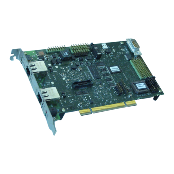
Page 29: Connectors Of The Eb 200
The following figure is a schematic representation of the connectors and jumper connectors, intended to help the user quickly find the required interfaces Figure 5: Connector Positions on the EB 200 Copyright © Siemens AG 2010. All rights reserved. EB 200 Manual Technical data subject to change... -
Page 30: Pci Interface
Command/byte enable AD[15] Address/data AD[14] Address/data +3.3 V Supply Ground AD[13] Address/data AD[12] Address/data AD[11] Address/data AD[10] Address/data Ground Ground AD[09] Address/data Copyright © Siemens AG 2010. All rights reserved. EB 200 Manual Technical data subject to change Version 1.1.4... -
Page 31: Table 12: Pin Assignment For Pci Interface
+5 V Supply +5 V Supply +5 V Supply Table 12: Pin Assignment for PCI Interface Key = Milling for PCI connector Copyright © Siemens AG 2010. All rights reserved. EB 200 Manual Technical data subject to change Version 1.1.4... -
Page 32: Lbu Interface
Polarity of LBU_RDY_N Ground +3.3 V Supply LBU_WR_N /Write LBU_BE1_N Command/Byte1 Enable LBU_DB15 15-bit data bus LBU_DB14 14-bit data bus +3.3 V Supply Copyright © Siemens AG 2010. All rights reserved. EB 200 Manual Technical data subject to change Version 1.1.4... -
Page 33: External Dc Power Supply
Connector type: Mini-DC power jack 3.5/1.3 mm Pin No. Signal Name Function Potential 6-9 V Ground 6-9 V Table 14: Pin Assignment for External DC Supply Copyright © Siemens AG 2010. All rights reserved. EB 200 Manual Technical data subject to change Version 1.1.4... -
Page 34: Double Ethernet Switch
Connector name: X7 (UART) Connector type: 9-pin SUB-D connector Signal Name Type Meaning Receive Data Transmit Data Ground Table 16: Pin Assignment for UART Copyright © Siemens AG 2010. All rights reserved. EB 200 Manual Technical data subject to change Version 1.1.4... -
Page 35: Gpio Interface
GPIO[27] GPIO OPIO[28] GPIO GPIO[29] GPIO GPIO[30] GPIO GPIO[31] GPIO Ground Ground Ground Table 18: Pin Assignment for GPIO [31 to .16] Copyright © Siemens AG 2010. All rights reserved. EB 200 Manual Technical data subject to change Version 1.1.4... -
Page 36: I/O Adapter
EMIF Address Bit 22 buffered B A[23] EMIF Address Bit 23 buffered Ground Table 20: Pin Assignment for X30 EMIF Address Bits Copyright © Siemens AG 2010. All rights reserved. EB 200 Manual Technical data subject to change Version 1.1.4... -
Page 37: Table 21: Pin Assignment For X31 Emif Data Bits
EXT INT N Interrupt for I/O expansion Ground Ground Ground Ground Ground Ground Table 22: Pin Assignment for Connectors of I/O Adapter Copyright © Siemens AG 2010. All rights reserved. EB 200 Manual Technical data subject to change Version 1.1.4... -
Page 38: Trace Interface
TRACEPKT8 TRACE data bit 8 = M for test board PIPESTAT0 TRACE Pipeline Status 0 Table 23: Pin Assignment for Trace Interface Copyright © Siemens AG 2010. All rights reserved. EB 200 Manual Technical data subject to change Version 1.1.4... -
Page 39: Jtag Interface
JTAG data out VSUPPLY 3.3 V JTAG test mode select JTAG data in Ground Table 25: Pin Assignment for Byte Blaster FPGA Programming Interface Copyright © Siemens AG 2010. All rights reserved. EB 200 Manual Technical data subject to change Version 1.1.4... -
Page 40: Cpld Programming Interface
Connector X10 is used to specify the boot modes and, in some cases, the configuration modes on the EB 200. Connector name: X10 Connector type: 2x8 pin male connector Signal Name Type Meaning BOOT[0] BOOT[1] BOOT[2] BOOT[3] CONFIG[1] CONFIG[2] CONFIG[3] CONFIG[4] Copyright © Siemens AG 2010. All rights reserved. EB 200 Manual Technical data subject to change Version 1.1.4... -
Page 41: System/Configuration Connector X11
Connector type: 2x8 pin male connector Signal Name Type Meaning CONFIG[5] CONFIG[6] SPI_CONFIG SYS_CONFIG[0] SYS_CONFIG[1] SYS_CONFIG[2] SYS_CONFIG[3] SYS_CONFIG[4] Table 28: Connector X11 for Configuration and System Settings Copyright © Siemens AG 2010. All rights reserved. EB 200 Manual Technical data subject to change Version 1.1.4... -
Page 42: Structure Of The Eb 200
RJ45 jack with LED’s link and activity 2 LED’s for board state signalisation e.g. RUN and SF Figure 6: Front Element of the EB 200 Copyright © Siemens AG 2010. All rights reserved. EB 200 Manual Technical data subject to change Version 1.1.4... -
Page 43: Table 29: Function Of Leds On Front Panel Of The Eb 200
200. Optionally, these LED outputs can be converted to a GPIO-alternative function. In this way, software can be used to control the LED activation. Copyright © Siemens AG 2010. All rights reserved. EB 200 Manual Technical data subject to change... -
Page 44: 10 Miscellaneous
System Control Register Block SDRAM Synchronous Dynamic RAM Standard Serial Peripheral Interface SRAM Static RAM Software UART Universal Asynchronous Receiver / Transmitter Warteschlange (queue) Copyright © Siemens AG 2010. All rights reserved. EB 200 Manual Technical data subject to change Version 1.1.4... -
Page 45: References
IEEE Standard Test Access Port and Boundary-Scan Architecture (1149.1 IEEE Boundary Scan 2001.PDF); ETM9 Technical Reference Manual (Rev. 2a) (ARM DDI 0157E) /10/ ETM Specification (ARM IHI 0014 H) Copyright © Siemens AG 2010. All rights reserved. EB 200 Manual Technical data subject to change Version 1.1.4...