Harman Kardon AVR 245 Owner's Manual
Audio/videoreceiver
Hide thumbs
Also See for AVR 245:
- Service manual (229 pages) ,
- Owner's manual (76 pages) ,
- Worksheet (3 pages)
Table of Contents
Advertisement
Advertisement
Table of Contents

Related Manuals for Harman Kardon AVR 245


Summary of Contents for Harman Kardon AVR 245
- Page 1 AVR 245 Audio/VideoReceiver OWNER’S MANUAL...
-
Page 2: Table Of Contents
Table of Contents Introduction Preset Tuning Programmed Device Functions Safety Information RDS Operation Volume Punch-Through Unpacking RDS Tuning Channel Control Punch-Through Front Panel Controls RDS Display Options Transport Control Punch-Through Rear Panel Connections Program Search Resetting the Remote Memory Main Remote Control Functions Programming the Remote Function List Installation and Connections... -
Page 3: Introduction
In addition to easy-to-use package. The AVR 245 takes the “video” part of its name the traditional 5.1 digital decoding modes such as seriously. Along with two HDMI inputs and three ■... -
Page 4: Safety Information
YOUR UNIT. extension cords be used with this product. As ■ Due to the weight of the AVR 245 and the heat with all electrical devices, do not run power cords generated by the amplifiers, there is the remote... -
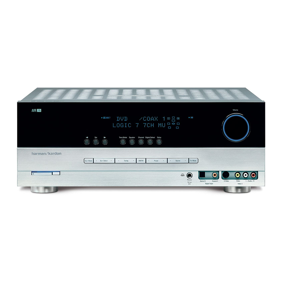
Page 5: Front Panel Controls
Front Panel Controls DIGITAL LOGIC 7 VID 1 PRO LOGIC VID 2 3 STEREO VID 3 FMAM 5 7 CH. STEREO VID 4 TAPE HEADPHONE 6 8 CH SURR. OFF Main Power Switch Tuner Band Selector Ô Video 4 input jacks System Power Control Set Button ... - Page 6 Front Panel Controls 7 Selector Buttons: When you are establishing $ Speaker/Channel Input Indicators: These Ó Digital Coax 3 Input: This jack is normally the AVR’s configuration settings, use these buttons indicators are multipurpose, indicating either the used for connection to the output of portable to select from the choices available, as shown in speaker type selected for each channel or the digital audio devices, video game consoles or...
-
Page 7: Rear Panel Connections
Green Digital Media Player (DMP) Surround Left: Blue Tape Inputs: Connect these jacks to the Connector: With the AVR 245 turned off, con- Surround Right: Gray PLAY/OUT jacks of an audio recorder. nect one end of the optional Harman Kardon... - Page 8 Rear Panel Connections 8-Channel Direct Inputs: These jacks are Surround Speaker Outputs: Connect Coaxial Digital Inputs: Connect the coax used for connection to source devices such as these outputs to the matching + and – terminals digital output from a DVD player, HDTV receiver, DVD-Audio or SACD players with discrete analog on your surround channel speakers.
- Page 9 DVD player, set-top box other remote controlled devices. Connect this or HDTV tuner to either of these jacks. jack to the “IR IN” jack on Harman Kardon or NOTE ON VIDEO CONNECTIONS: When con- other compatible equipment.
-
Page 10: Main Remote Control Functions
Main Remote Control Functions Power Off Button IR Transmitter Window Program Indicator Power On Button Input Selectors AVR Selector AM/FM Tuner Select 6-Channel/8-Channel Direct Input Test Button Sleep Button Surround Mode Selector Night Mode Channel Select Button Buttons ⁄ ¤ Button ‹... -
Page 11: Programming The Remote
Pressing this button when the tuner is in use will most Harman Kardon CD or DVD players and cas- tion on using these buttons for each application. select between the AM and FM bands. - Page 12 Main Remote Control Functions OSD Button: Press this button to activate installed. (See page 22 for more information on Mute: Press this button to momentarily the On Screen Display (OSD) system used to set stereo playback modes). silence the AVR or TV set being controlled, up or adjust the AVR’s parameters.
-
Page 13: Installation And Connections
1. Connect a VCR’s audio and video Play/Out you will need to connect its analog audio outputs referred to your installer or a licensed electrician to the appropriate inputs on the AVR 245, as the jacks to the Video 2 In jacks on the rear who is familiar with the applicable local building panel. -
Page 14: Hdmi Connections
AVR 245 is used with HDMI sources: that the remote control is preprogrammed with puts of that device to the Front Panel Inputs •... - Page 15 Installation and Connections In that case the following Scart to Cinch Black adapters or cables are needed: Figure 1: Yellow SCART/Cinch-Adapter • Units for playback, such as satellite receivers, for playback; camcorders, DVD or LD players, need an signal flow: adapter from Scart to 3 RCA plugs, see fig.
-
Page 16: System And Power Connections
Depending on your system`s requirement and This unit is equipped with one accessory AC out- The AVR 245 is designed for flexible use with distance from the AVR to the remote room, three lets. It may be used to power Accessory devices,... -
Page 17: Speaker Selection
It is appropriate to configure the AVR 245 for listening position. Ideally, the front-channel either 5.1- or 7.1-channel operation, but not for speakers should be placed so that their tweeters 6.1 channels. -
Page 18: System Configuration
Selector buttons ‹ › the on-screen menus are not available when a ready to power up the AVR 245 to begin these on the front panel or remote. ⁄ ¤ component video display is in use. -
Page 19: Input Setup
Video 1 Component Video panel Input Indicators by the blue LED next The factory default settings for the AVR 245 have Input to be assigned to the DVD, with the to the desired input name. -
Page 20: Surround Setup
➞ buttons until the cursor is next to the remote so that it operates the AVR 245. You may your source input, you will notice that the menu. Press the SURROUND SELECT then press the OSD Button and use the... -
Page 21: Night Mode Settings
“R-3” Matrix) available in the AVR 245 will not appear for 6.1/7.1 operation by configuring the Surround for a deeper, rear-oriented sound to “F-3” for a unless a digital source is playing the correct Back speakers to “Small”... -
Page 22: Configuring The Surround Off (Stereo) Modes
System Configuration : When MAX is in the highlighted video, AVR 245 defaults to the DTS surround mode, but After the selections are made in the Dolby, DTS, a more severe compression algorithm will be reproduces the higher-resolution materials that Logic 7, DSP (Surround) or Stereo menus, press applied. -
Page 23: Automated Speaker Setup Using Ezset
EzSet+ loud sounds and do not use some sort of ear pro- The AVR 245 is one of the first receivers in its menus by first pressing the OSD Button tection, we strongly recommend that you leave class to offer automated speaker setup and sys- bring the Master Menu to the screen. - Page 24 System Configuration While this screen is visible, you may start and sage in the last line of the menu screen change • Speaker Size: The measurements and calcula- stop the calibration process, or monitor the as the volume level is adjusted. tions for this test take place at the same time progress of the measurements and view the as the test signals are circulated to calculate...
-
Page 25: Manual Setup
(as far as speakers are used with them) Buttons o to change this setting to AVR 245. For those situations where you may and need not be repeated when another sur- you wish to reset the speaker size, crossover, out- wish to make a change to the settings entered by round mode is selected with that input. - Page 26 System Configuration It is easiest to enter the proper settings for the If you wish to customize the speaker size individ- remove all digital processing from the circuit speaker setup through the ually to each input, make certain that the cursor path, select this configuration.
- Page 27 System Configuration 5. When you have completed your selection for When is selected, the system will adjust appears in the on-screen menu. When this NONE the center channel, press the Button so that only 5.1-channel surround processing/ option is selected, a full-range signal will be ¤...
-
Page 28: Delay Settings
System Configuration To change the setting for any of the four speaker Important Note: All settings for the crossover groups Left/Right, Center, Surround or Surround points will be "Global", i.e. they will be identical Back, press the Buttons until the cur- for all inputs no matter if the BASSMANAGER ⁄... -
Page 29: Output Level Adjustment
System Configuration ➞ To re-synchronize the front, center and surround Next move the cursor to the line and Note that the A/V Sync delay setting is unique to UNIT channels at first measure and note the distance select the unit for distances you prefer to enter, each video input source, so you may enter a dif- ➞... - Page 30 System Configuration Artificially increasing the volume to the rear 4. Manual output level adjustment is most easily NOTE: Remember to verify that the speakers have speakers may destroy the illusion of an envelop- done through the been properly connected. As the test noise CHANNEL ADJUST ing sound field that duplicates the way you hear menu (Figure 12).
- Page 31 System Configuration by pressing the Navigation Button The output levels may also be adjusted at any Once the settings outlined on the previous pages ⁄ ¤ until the ➞ cursor is pointing to the time using the remote control and semi-OSD sys- have been made, the AVR is ready for operation.
-
Page 32: Operation
Logic 7 Cinema Exclusive to Harman Kardon for AV receivers, Logic 7 is an advanced mode that extracts the Logic 7 Music maximum surround information from either surround-encoded programs or conventional stereo material. - Page 33 Operation Surround Mode Chart MODE FEATURES DTS Neo:6 Cinema These two modes are available when any analog source is playing to create a six-channel DTS Neo:6 Music surround presentation from conventional Matrix-encoded and traditional Stereo sources. Select the Cinema version of Neo:6 when a program with any type of analog Matrix surround encoding is present.
-
Page 34: Basic Operation
Apple iPod of the button will increase the time before shut in use and the tone or balance controls will not device is inserted in an optional Harman Kardon down in the following sequence: function. -
Page 35: Controls And Use Of Headphones
Information Display Ò. One of the most important features of the However, for stereo programs without any AVR 245 is its ability to reproduce a full multi- Digital Audio Playback surround information the Theater, Hall and 5/7CH channel surround sound field from digital... -
Page 36: Dolby Digital
Operation Dolby Digital PCM Audio Playback When the digital source is playing, the AVR will PCM (Pulse Code Modulation) is the non- com- automatically detect whether it is a multichannel Dolby Digital (originally known as AC-3 ® ) is a pressed digital audio system used for compact Dolby Digital or DTS source or a conventional standard part of DVD, and is available on special-... -
Page 37: Surround Mode Post Processing
When that occurs, right signals are available. This will be displayed Thanks to the power of the AVR 245’s DSP the unit’s digital signal processor has no signal to for Dolby Digital 5.1 and DTS 5.1 programs. -
Page 38: Pcm Playback Indications
Operation For incoming DTS signals, the following modes are available: Incoming Bitstream Available Surround Modes DTS 1/0/.0, 1/0/.1, 2/0/.0, 2/0/.1, 3/0/.0, 3/0/.1, 3/1/.0 or 3/1/.1 DTS, DTS Stereo DTS 2/2/.0, 2/2/.1, 3/2/.0 or 3/2/.1 DTS, DTS Stereo, DTS+Neo:61, DTS+Pro Logic IIx Movie*, DTS+Pro Logic IIx Music* DTS 96/24 DTS 96/24, DTS Stereo, DTS+Neo:6*, DTS+Pro Logic IIx Movie*, DTS+Pro Logic IIx Music* DTS-ES Matrix... -
Page 39: Night Mode
The AVR will automatically sense input signal for the surround back channels. the type of digital surround encoding used, When Harman Kardon’s (optional) is indicate it in the Channel Input Indicators $ The letters used by the Speaker/Channel Input connected and a compatible Apple ®... -
Page 40: Output Level Adjustment With Source Signals
Operation controls on the iPod. Complete details on operat- The channel output may also be adjusted using NOTE: The output levels may be separately ing an iPod using and an AVR remote the full-OSD on-screen menu system. First, set trimmed for each digital and analog surround are furnished with the volume to a comfortable listening level using mode. -
Page 41: System Setup
System Setup The AVR 245 is equipped with a number of ad- Turn On Volume Level Semi-OSD Settings vanced features that add extra flexibility to the As is the case with most audio/video receivers, The semi-OSD system places one line messages unit’s operation. -
Page 42: Full-Osd Time Out Adjustment
This setting will be retained even when the will automatically switch the appropriate default AVR 245 is turned off to the Standby mode. surround mode, with the AVR responding to the data flags that are encoded on the DVD disc or If you wish to make other adjustments, press the until the on-screen ➝... -
Page 43: Multiroom Operation
Multiroom Operation desired volume level for the multi-room system is Left/Right amplifier channels are used to power The AVR 245’s multiroom system is accessed entered. DO NOT use the regular volume control the remote zone, make certain that the system is using the on-screen knobs for this setting. -
Page 44: Multiroom Operation
IR Input jack on compatible optional IR sensor and the remote control in the Harman Kardon audio components such as CD, remote location. DVD or cassette players, the transport functions... -
Page 45: Tuner Operation
NOTE: When the FM reception of a stereo station is weak, audio quality will be increased The AVR 245’s tuner is capable of tuning AM, FM by switching to Mono mode by pressing the and FM Stereo broadcast stations and receiving... -
Page 46: Rds Operation
Some RDS stations may not include some of • COUNTRY: Country Music these additional features. If the data required for The AVR 245 is equipped with RDS (Radio Data • NATIONAL: National Music the selected mode is not being transmitted, the System), which brings a wide range of informa- Main Information Display Ò... -
Page 47: Programming The Remote
Programming the Remote The AVR 245 is equipped with a powerful remote 5. If the Power function of the unit to be pro- 3. To find out if the code for your unit is pre-pro- control that will control not only the receiver’s... -
Page 48: Macro Programming
Programming the Remote Example: One blink, followed by a one-second • Press the Macro 1 button and Mute For some products, however, the function of a pause, followed by six blinks, followed by a one- buttons at the same time and then release them. particular button does not follow the command second pause, followed by four blinks indicates •... -
Page 49: Channel Control Punch-Through
Programming the Remote To program the remote for Volume Punch- 3. Press and release the AVR or Input Resetting the Remote Memory Through, follow these steps: Selector button for the device that will be As you add components to your home-theater used to change the channels. -
Page 50: Function List
Function List Button Name AVR Function CD/CD-R Tape Power On Power On Power On Power On Power On Power Off Power Off Power Off Power Off Power Off Mute Mute Mute Mute Mute AVR Select AVR Select AVR Select AVR Select DVD/ DVD Input Select DVD Select... - Page 51 Function List Button Name VCR (VID 1) TiVo (VID 1) CBL (VID 2) SAT (VID 2) TV (VID 3) (DMP) HDMI 1/2 Power On Power On Power On Power On Power On Power On Power Off Power Off Power Off Power Off Power Off Power Off...
-
Page 52: Troubleshooting Guide
Power switch 2 is red due to possible short and speaker ends • Amplifier is in protection mode • Contact your local Harman Kardon service depot due to internal problems No sound from surround or • Incorrect surround mode •... -
Page 53: Technical Specifications
Depth measurement includes knobs, buttons and terminal connections. Height measurement includes feet and chassis. All features and specifications are subject to change without notice. Harman Kardon, The Bridge and Logic 7 are registered trademarks of Harman International Industries, Incorporated. is a trademark of Harman International Industries, Inc. -
Page 54: Appendix - Settings Worksheet
APPENDIX – SETTINGS WORKSHEET Appendix – Default settings, worksheets, remote product codes Table A1 – Source Input Setting Defaults Source HDMI 1 HDMI 2 Video 1 Video 2 Video 3 Video 4 The Bridge/ CD Tape Tuner 6-/8- Channel Title INT.TUNER Component Comp V 1 Convert*** Convert*** Comp V 2 Comp V 3 Convert*** Convert*** Convert*** Convert*** Convert*** Convert*** Convert***... - Page 55 APPENDIX – SETTINGS WORKSHEET Table A4 – Source Input Settings Source HDMI 1 HDMI 2 Video 1 Video 2 Video 3 Video 4 The Bridge/DMP CD Tape Tuner 6-/8-Channel Title Int. Tuner Video Input Component Video Input Audio Input The Bridge/DMP Tuner 6-Channel Auto Poll...
- Page 56 250 Crossways Park Drive, Woodbury, New York 11797 www.harmankardon.com Harman Consumer Group, Inc.: 2, route de Tours, 72500 Château-du-Loir, France © 2007 Harman Kardon, Incorporated Part No.: OM P/N CQX1A1136Z...