Harman Kardon AVR 240 Owner's Manual
Harman consumer group audio/videoreceiver owner's manual avr 240
Hide thumbs
Also See for AVR 240:
- Service manual (156 pages) ,
- Owner's manual (64 pages) ,
- Quick start manual (4 pages)
Table of Contents
Advertisement
Quick Links
Advertisement
Table of Contents

Related Manuals for Harman Kardon AVR 240


Summary of Contents for Harman Kardon AVR 240
- Page 1 AVR 240 Audio/VideoReceiver OWNER’S MANUAL Power for the Digital Revolution ®...
-
Page 2: Table Of Contents
Table of Contents Introduction Safety Information Unpacking Front Panel Controls Rear Panel Connections Main Remote Control Functions Installation and Connections Audio Connections Video Connections SCART A/V Connections System and Power Connections Speaker Selection Speaker Placement System Configuration First Turn On Using the On-Screen Display System Setup Input Setup... -
Page 3: Introduction
Introduction Thank you for choosing Harman Kardon! With the purchase of a Harman Kardon AVR 240 you are about to begin many years of listening enjoyment. Designed to provide all the excitement and detail of movie soundtracks and every nuance of musical selections, the AVR 240 is truly a multichannel receiver for the new millennium. -
Page 4: Safety Information
■ Do not obstruct the ventilation slots on the top of the unit, or place objects directly over them. ■ Due to the weight of the AVR 240 and the heat generated by the amplifiers, there is the remote possibility that the rubber padding on the bottom of the unit’s feet may leave marks... -
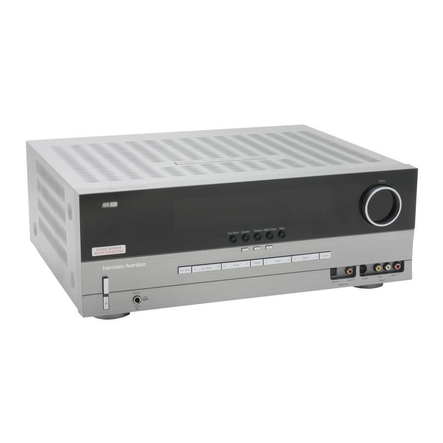
Page 5: Front Panel Controls
Front Panel Controls Main Power Switch System Power Control Power Indicator Headphone Jack Surround Mode Group Selector Speaker Select Button Selector Buttons Tone Mode Surround Mode Selector Tuning 1 Main Power Switch: Press this button to apply power to the AVR. When the switch is pressed in, the unit is placed in a Standby mode, as indicated by the orange LED 3. - Page 6 Front Panel Controls 7 Selector Buttons: When you are establishing the AVR’s configuration settings, use these buttons to select from the choices available, as shown in the Main Information Display Ò. 8 Tone Mode: Pressing this button enables or disables the Balance, Bass and Treble tone controls.
-
Page 7: Rear Panel Connections
RECORD/INPUT audio jacks on a VCR or any other Audio recorder. Digital Media Player (DMP) Connector: With the AVR 240 turned off, con- nect one end of the optional Harman Kardon to this proprietary connector, and the other to your compatible Apple iPod. - Page 8 VCR, DVD player, satellite receiver, cable set-top box, personal video recorder or video game to the AVR 240, you may use either a composite or S-video connection, but not both. Remote IR Output: This connection per- mits the IR sensor in the receiver to serve other remote controlled devices.
-
Page 9: Main Remote Control Functions
Main Remote Control Functions Power Off Button IR Transmitter Window Program Indicator Power On Button Input Selectors AVR Selector AM/FM Tuner Select 6-Channel/8-Channel Direct Input Test Button Sleep Button Surround Mode Selector Night Mode Channel Select Button Buttons ⁄ ¤ Button ‹... - Page 10 Main Remote Control Functions IMPORTANT NOTE: The AVR 240’s remote may be programmed to control up to seven devices, including the AVR. Before using the remote, it is important to remember to press the Input Selector button that corresponds to the unit you wish to operate.
- Page 11 ® is docked in pressing this selector will select the iPod as the audio source input device for the AVR 240. In addition, if a video display is connected to one of the Video Monitor Outputs , the iPod’s messages will appear on screen, and in the Upper and Lower Display Lines Ò.
-
Page 12: Installation And Connections
Note that if the antenna or connec- tion uses 300-ohm twin-lead cable, you should use a 300-ohm-to-75-ohm adapter to make the connection. 7. With the AVR 240 turned off, connect the optional Harman Kardon Digital Media Player (DMP) Connector Your compatible Apple ®... -
Page 13: Scart A/V Connections
Installation and Connections 2. Although any video device may be connected to these jacks, we recommend connecting your video recorder to the Audio 1 Audio/Video Input Jacks so that you may take advan- tage of the fact that the remote control is pre- programmed with video recorder product codes for the Video 1 device. -
Page 14: System And Power Connections
For that reason, it is important that only the cord supplied with the unit (or a direct replacement of identical capaci- ty) be used. Once the power cord is connected, you are almost ready to enjoy the AVR 240’s incredible power and fidelity! -
Page 15: Speaker Selection
The speakers should be no more than 2 meters behind the rear of the seating area. It is appropriate to configure the AVR 240 for either 5.1- or 7.1-channel operation, but not for 6.1 channels. When 6.1-channel program material or a 6.1-channel processing mode is in... -
Page 16: System Configuration
A D V A N C E D Figure 1 System Setup The AVR 240 features an advanced memory sys- tem that enables you to establish different con- figurations for the speaker configuration, digital input, surround mode, delay times, crossover fre- quencies and speaker setting for each input source. -
Page 17: Input Setup
Before beginning the EzSet+ procedure, there are a few adjustments that need to be made to ensure accurate results. The factory default settings for the AVR 240 have all inputs configured for an analog audio input except for the DVD input, where the Coaxial... -
Page 18: Audio Setup
AVR 240 is in Standby mode to indicate that charging is taking place. The default setting is , in which the docked iPod will not continue to charge when the AVR 240 is turned off, even though remains connected to the AVR. -
Page 19: Night Mode Settings
System Configuration To select the mode that will be used as the initial default for an input, first press the buttons ⁄ ¤ until the on-screen cursor is next to the desired mode’s master category name. Next, press the Set Button to view the sub-menu. -
Page 20: Configuring The Surround Off
Automated Speaker Setup Using EzSet+ The AVR 240 is one of the first receivers in its class to offer automated speaker setup and sys- tem calibration. This process greatly simplifies the installation of your new receiver by using a series... - Page 21 Step 3: Plug the EzSet+ microphone into the AVR 240’s Headphone Jack 4, making certain that the mini-plug to 1/4" phone plug adaptor supplied with the microphone is firmly connected.
-
Page 22: Manual Setup
Basic Operation section of this manual on page 30 to learn how to operate AVR 240. For those situations where you may wish to make a change to the settings entered by EzSet+, follow the instructions on the follow- ing pages. -
Page 23: Speaker Setup
System Configuration The first line of the MANUAL SETUP menu indicates whether EzSet+ has been run and its settings saved. If this line indicates Y E S, then you will be able to see the settings determined by EzSet+ as you view the SPEAKER S I Z E, SPEAKER X - O V E R, DELAY ADJUST and CHANNEL ADJUST submenus. - Page 24 System Configuration NOTE: When the front speakers are set to the option and the surround mode is set to LARGE "Surround Off", or pure two-channel stereo, when an analog signal source is present it will be routed directly from the input to the volume control without being digitized or processed.
- Page 25 System Configuration subwoofer will receive the front left and right bass frequencies under the crossover frequency selected in another setting on this menu, as described below, and also the LFE soundtrack. 9. When all initial speaker “size” settings have been made, you now have the option to take advantage of the AVR’s Quadruple Crossover system, which allows individual crossover settings to be made for...
-
Page 26: Delay Settings
System Configuration Delay Settings Due the different distances between the listening position for the front channel speakers and the surround speakers, the amount of time it takes for sound to reach your ears from the front or surround speakers is different. You may compen- sate for this difference through the use of the delay settings to adjust the timing for the specif- ic speaker placement and acoustic conditions in... -
Page 27: Output Level Adjustment
System Configuration setting. The Navigation Button ⁄ ¤ may be used to select another position, or you may simply wait five seconds for the system to time out and return to normal operation. The delay settings may be adjusted at any time using the remote control and while viewing an on-screen image by pressing the Delay Select Button... - Page 28 System Configuration NOTE: Remember that when your system has only a single Surround Back speaker and is thus configured for 6.1-channel operation, you will hear the test tone twice from the back speaker, once with the SBL indication and once with the SBR indication.
- Page 29 System Configuration Once the settings outlined on the previous pages have been made, the AVR is ready for operation. While there are some additional settings to be made, these are best done after you have had an opportunity to listen to a variety of sources and different kinds of program material.
-
Page 30: Operation
Operation Surround Mode Chart MODE FEATURES DOLBY DIGITAL Available only with digital input sources encoded with Dolby Digital data. It provides up to five separate main audio channels and a special dedicated Low Frequency Effects channel. DOLBY DIGITAL EX Available when the receiver is configured for 6.1/7.1 channel operation, Dolby Digital EX is the latest version of Dolby Digital. - Page 31 Operation Surround Mode Chart MODE FEATURES DTS Neo:6 Cinema These two modes are available when any analog source is playing to create a six-channel DTS Neo:6 Music surround presentation from conventional Matrix-encoded and traditional Stereo sources. Select the Cinema version of Neo:6 when a program with any type of analog Matrix surround encoding is present.
-
Page 32: Basic Operation
Operation Basic Operation Once you have completed the setup and configu- ration of the AVR, it is simple to operate and enjoy. The following instructions should be followed for you to maximize your enjoyment of your new receiver: Turning the AVR On or Off •... -
Page 33: Surround Mode Selection
Surround Mode Selection One of the most important features of the AVR 240 is its ability to reproduce a full multi- channel surround sound field from digital sources, analog matrix surround encoded programs and standard stereo or even mono programs. -
Page 34: Dts
Operation DTS is another digital audio system that is capa- ble of delivering 5.1, 6.1 or 7.1 audio. Although both DTS and Dolby Digital are digital, they use different methods of encoding the signals, and thus they require different decoding circuits to convert the digital signals back to analog. -
Page 35: Pcm Playback Indications
Operation message may appear in the UNLOCK Lower Display Line Ò. This is your indication that the digital audio data stream has been inter- rupted or is no longer present. When that occurs, the unit’s digital signal processor has no signal to lock onto, and is thus “unlocked.”... -
Page 36: Night Mode
Operation back speakers may light (when those speakers have been configured) to indicate that a signal will be fed to them (Matrix decoded with NEO:6, LOGIC 7 or 7 CH Stereo), but no letters inside will light as the unit will not receive an input sig- nal for the surround back channels. -
Page 37: Memory Backup
Advanced Features The AVR 240 is equipped with a number of ad- vanced features that add extra flexibility to the unit’s operation. While it is not necessary to use these features to operate the unit, they provide additional options that you may wish to use. -
Page 38: Turn-On Volume Level
Advanced Features Turn On Volume Level As is the case with most audio/video receivers, when the AVR is turned on, it will always return to the volume setting in effect when the unit was turned off. However, you may prefer to always have the AVR turn on at a specific set- ting, regardless of what was last in use when the unit was turned off. -
Page 39: Default Surround Mode
Basic Tuner Operation The AVR 240’s tuner is capable of tuning AM, FM and FM Stereo broadcast stations and receiving RDS data. Stations may be tuned manually, or they may be stored as favorite station presets and recalled from a 30 position memory. -
Page 40: Rds Operation
Tuner Operation RDS Operation The AVR 240 is equipped with RDS (Radio Data System), which brings a wide range of informa- tion to FM radio. Now in use in many countries, RDS is a system for transmitting station call signs... -
Page 41: Programming The Remote
Programming the Remote The AVR 240 is equipped with a powerful remote control that will control not only the receiver’s functions, but also most popular brands of audio and video equipment, including CD players, TV sets, cable boxes, VCRs, satellite receivers and other home-theater equipment. -
Page 42: Macro Programming
Programming the Remote Example: One blink, followed by a one-second pause, followed by six blinks, followed by a one- second pause, followed by four blinks indicates that the code has been set to 164. For future reference enter the Setup Codes for the equipment in your system here: DVD ____________ CD ________________ VID1/VCR ________ VID3/TV __________... -
Page 43: Channel Control Punch-Through
Programming the Remote To program the remote for Volume Punch- Through, follow these steps: 1. Press the Input Selector for the unit you wish to have associated with the volume control and the Mute button at the same time until the red light illuminates under the Input Selector and note that the Program Indicator will flash amber. -
Page 44: Function List
Function List 44 FUNCTION LIST Button Name AVR Function Power On Power On Power Off Power Off Mute Mute AVR Select DVD Input Select CD Input Select Tape Tape Input Select VID 1 Video 1 Select VID 2 Video 2 Select VID 3 Video 3 Select VID 4... - Page 45 Function List Button Name Tape Power On Power On Power Off Power Off Mute Tape Tape Select VID 1 VID 2 VID 3 VID 4 Video 4 Select AM/FM 6/8 Ch. Select Sleep Test T/V select Volume Up Surround Select Night Spare Button Volume Down...
-
Page 46: Troubleshooting Guide
Troubleshooting Guide SYMPTOM CAUSE Unit does not function when Main • No AC Power Power Switch 1 is pushed Display lights, but no sound • Intermittent input connections or picture • Mute is on • Volume control is down No sound from any speaker; •... -
Page 47: Technical Specifications
Technical Specifications Audio Section Stereo Mode Continuous Average Power (FTC) 65 Watts per channel, 20Hz–20kHz, @ < 0.07% THD, both channels driven into 8 ohms 7 Channel Surround Modes Power Per Individual Channel Front L&R channels: 50 Watts per channel, @ <... -
Page 48: Appendix - Settings Worksheet
APPENDIX – SETTINGS WORKSHEET Table 1: Input Settings FEATURE Input Title Component Component Component Component Component Video Input Video 1 (Y/N) Digital Audio Input Auto Poll (On/Off) Surround Mode Night Mode Front L/R Speaker Size* Center Speaker Size* Surround L/R Speaker Size* Surround Back Speaekr Size* Subwoofer Front L/R Crossover... - Page 49 INTRODUCTION 49...
- Page 50 250 Crossways Park Drive, Woodbury, New York 11797 www.harmankardon.com Harman Consumer Group International: 2, route de Tours, 72500 Château-du-Loir, France © 2005 Harman Kardon, Incorporated Part No.: OM P/N CQX1A1056Z...