Table of Contents
Advertisement
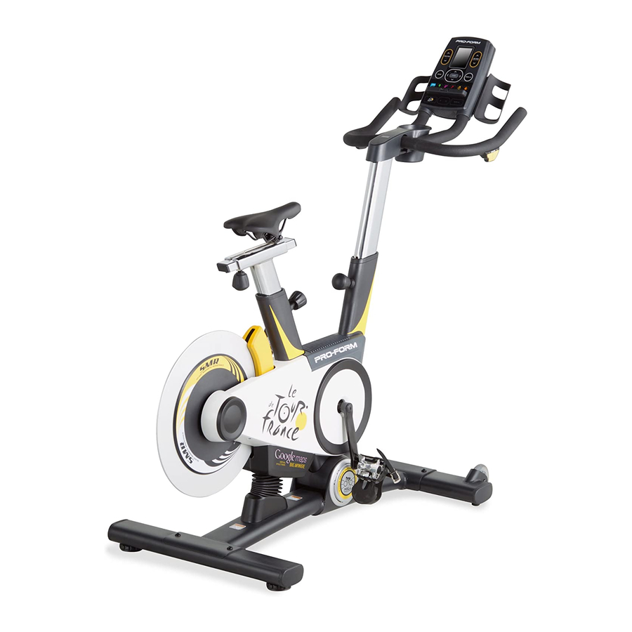
www.proform.com
Model No. PFEX01312.0
Serial No.
Write the serial number in the space
above for reference.
Serial Number
Decal
QUESTIONS?
If you have questions, or if parts
are damaged or missing, DO NOT
CONTACT THE STORE; please
contact Customer Care.
IMPORTANT: Please register this
product (see the limited warranty
on the back cover of this manual)
before contacting Customer Care.
CALL TOLL-FREE:
1-877-660-1168
Mon.––Fri., 6 a.m.––6 p.m. MT
Sat. 8 a.m.––4 p.m. MT
ON THE WEB:
www.proformservice.com
CAUTION
Read all precautions and instruc-
tions in this manual before using
this equipment. Keep this manual
for future reference.
USER’'S MANUAL
Advertisement
Table of Contents

Related Manuals for Pro-Form Le Tour De France PFEX01312.0


Summary of Contents for Pro-Form Le Tour De France PFEX01312.0
- Page 1 Model No. PFEX01312.0 Serial No. Write the serial number in the space USER’’S MANUAL above for reference. Serial Number Decal QUESTIONS? If you have questions, or if parts are damaged or missing, DO NOT CONTACT THE STORE; please contact Customer Care.
-
Page 2: Table Of Contents
TABLE OF CONTENTS WARNING DECAL PLACEMENT ............. . . 2 IMPORTANT PRECAUTIONS . -
Page 3: Important Precautions
IMPORTANT PRECAUTIONS WARNING: To reduce the risk of serious injury, read all important precautions and instructions in this manual and all warnings on your exercise bike before using your exercise bike. ICON assumes no responsibility for personal injury or property damage sustained by or through the use of this product. -
Page 4: Before You Begin
BEFORE YOU BEGIN Congratulations for selecting the revolutionary reading this manual, please see the front cover of this PROFORM LE TOUR DE FRANCE exercise bike. manual. To help us assist you, note the product model ® ® The LE TOUR DE FRANCE exercise bike is unlike any number and serial number before contacting us. -
Page 5: Part Identification Chart
PART IDENTIFICATION CHART Use the drawings below to identify the small parts needed for assembly. The number in parentheses below each drawing is the key number of the part, from the PART LIST near the end of this manual. The number following the key number is the quantity needed for assembly. -
Page 6: Assembly
ASSEMBLY •• To hire an authorized service technician to assem- •• In addition to the included tool(s), assembly ble the exercise bike, call 1-800-445-2480. requires the following tools: one Phillips screwdriver •• Assembly requires two persons. two adjustable wrenches •• Place all parts in a cleared area and remove the packing materials. - Page 7 2. While a second person lifts the rear of the Base (1), attach the Rear Stabilizer (23) to the Base with two 3/8" x 2 1/4" Screws (74). 3. Orient the Seat Post (3) as shown. Loosen the indicated Post Knob (47) and pull it outward.
- Page 8 5. Slide the Seat (5) onto the post on the Seat Carriage (4). Make sure that the Seat is level and that it is pointing straight forward. Then, tighten the two nuts (not shown) beneath the Seat. 6. Orient the Handlebar Post (6) as shown. Have a second person hold the Handlebar Post Avoid pinching the (6) near the Frame (2).
- Page 9 8. Orient the Handlebar Cover (91) as shown and hold it near the Handlebar (7). Wire Connect the wire on the receiver (not shown) to the Extension Wire (102). Insert the excess wire into the Handlebar (7). Tip: Avoid pinching the wires. Insert a #8 x 5/8"...
-
Page 10: How To Use The Exercise Bike
HOW TO USE THE EXERCISE BIKE HOW TO PLUG IN THE POWER CORD A temporary adapter may 2-pole Receptacle This product must be grounded. If it should be used to malfunction or break down, grounding provides a path connect the Adapter of least resistance for electric current to reduce the power cord... - Page 11 HOW TO ADJUST THE ANGLE OF THE SEAT HOW TO ADJUST THE HANDLEBAR POST You can adjust the angle of the seat to the position that To adjust the height is most comfortable. You can also slide the seat for- of the handlebar ward or backward to increase your comfort or to adjust post, first loosen the...
-
Page 12: Console Diagram/Features
CONSOLE DIAGRAM FEATURES OF THE CONSOLE While you exercise, the console will display continuous exercise feedback. You can also measure your heart The advanced console offers an array of features rate using an optional heart rate monitor. designed to make your workouts more effective and enjoyable. - Page 13 HOW TO TURN ON THE POWER HOW TO SET UP THE CONSOLE IMPORTANT: If the exercise bike has been exposed Before using the exercise bike for the first time, set up to cold temperatures, allow it to warm to room your console.
- Page 14 HOW TO USE THE MANUAL MODE 6. Follow your progress with the display. 1. Begin pedaling or press any button on the The display can show the following workout console to turn on the console. information. Press the Display button or the left, right, up, and down buttons to view the desired See HOW TO TURN ON THE POWER on workout information.
- Page 15 Time——This display mode will show the elapsed 7. Wear a heart rate monitor and measure your time. heart rate if desired. Watts——This display will show your approximate You can wear an optional heart rate monitor to power output in watts. measure your heart rate.
- Page 16 HOW TO USE AN ONBOARD WORKOUT The display will also show a map of the trail and a marker indicating your progress. Press the Display 1. Begin pedaling or press any button on the button repeatedly to view the map. console to turn on the console.
- Page 17 HOW TO USE AN IFIT LIVE WORKOUT Before some workouts will download, you must add them to your schedule on iFit.com. Note: To use an iFit Live workout, you must have access to a wireless network including an 802.11b/n For more information about the iFit Live work- router with SSID broadcast enabled (hidden networks outs, please see www.iFit.com.
-
Page 18: The Settings Mode
HOW TO USE THE SETTINGS MODE The display will inform you when the console has connected to your wireless network. Press the The console features a settings mode that allows you Enter button to close the standard setup mode. to connect the console to your own wireless network and to log in to your iFit Live account. - Page 19 4. Select a language. 7. Turn on or turn off the incline lockout. From the settings menu, select International. Then, The console features an incline lockout that will select Language. The currently selected language prevent the exercise bike from inclining or will be highlighted.
- Page 20 HOW TO USE THE MAINTENANCE MODE 4. Restore the default settings. The console features a maintenance mode that allows From the maintenance menu, select Restore you to update the console firmware, restore the default Defaults. Then, press Enter to restore the console settings, view technical information, perform a network to the original settings from the factory.
-
Page 21: Fcc Information
HOW TO USE THE SOUND SYSTEM THE OPTIONAL HEART RATE MONITOR To play music or audio books through the console Whether your sound system while you exercise, plug your audio goal is to cable into the jack on the console and into a jack on burn fat or to your MP3 player or CD player;... -
Page 22: Maintenance And Troubleshooting
MAINTENANCE AND TROUBLESHOOTING HOW TO MAINTAIN THE EXERCISE BIKE Plug in the power cord and press the power switch to the reset position. Rotate the Crank Pulley (53) for a Inspect and tighten all parts of the exercise bike regu- moment. -
Page 23: Exercise Guidelines
EXERCISE GUIDELINES Aerobic Exercise——If your goal is to strengthen your WARNING: cardiovascular system, you must perform aerobic Before beginning this exercise, which is activity that requires large amounts or any exercise program, consult your physi- of oxygen for prolonged periods of time. For aerobic cian. - Page 24 SUGGESTED STRETCHES The correct form for several basic stretches is shown at the right. Move slowly as you stretch ——never bounce. 1. Toe Touch Stretch Stand with your knees bent slightly and slowly bend forward from your hips. Allow your back and shoulders to relax as you reach down toward your toes as far as possible.
-
Page 25: Part List
PART LIST Model No. PFEX01312.0 R0312A Key No. Qty. Description Key No. Qty. Description Base Post Bushing Frame Post Knob Seat Post Power Switch Seat Carriage Grommet Seat Control Board Handlebar Post Board Bracket Handlebar Standoff Tray Crank Pulley Console... - Page 26 Key No. Qty. Description Key No. Qty. Description Handlebar Cover 1/4" Split Washer #8 x 1/4" Screw M3.5 x 13mm Screw #8 Star Washer 5/16" x 2 1/4" Screw #8 x 5/8" Screw 5/16" x 3/4" Screw #8 x 1/2" Screw ––...
-
Page 27: Exploded Drawing
EXPLODED DRAWING Model No. PFEX01312.0 R0312A 48 49... -
Page 28: Ordering Replacement Parts
ORDERING REPLACEMENT PARTS To order replacement parts, please see the front cover of this manual. To help us assist you, be prepared to provide the following information when contacting us: •• the model number and serial number of the product (see the front cover of this manual) ••...