Table of Contents
Advertisement
Quick Links
Extron USA - West
Extron USA - East
Extron Europe
Headquarters
+800.633.9876
+800.3987.6673
+800.633.9876
Inside USA / Canada Only
Inside Europe Only
Inside USA / Canada Only
+1.919.863.1794
+31.33.453.4040
+1.714.491.1500
+1.919.863.1797 FAX
+31.33.453.4050 FAX
+1.714.491.1517 FAX
© 2009 Extron Electronics. All rights reserved.
Extron Asia
Extron Japan
Extron China
Extron Middle East
+800.7339.8766
+81.3.3511.7655
+400.883.1568
+971.4.2991800
Inside Asia Only
+81.3.3511.7656 FAX
Inside China Only
+971.4.2991880 FAX
+65.6383.4400
+86.21.3760.1568
+65.6383.4664 FAX
+86.21.3760.1566 FAX
User's Manual
FOXBOX 4G Tx / Rx VGA
FOXBOX 4G Tx / Rx DVI
High Resolution Fiber Optic Transmitters and Receivers
68-1464-01 Rev. A
01 09
Advertisement
Table of Contents

Related Manuals for Extron electronics FOXBOX 4G Tx


Summary of Contents for Extron electronics FOXBOX 4G Tx
- Page 1 User’s Manual FOXBOX 4G Tx / Rx VGA FOXBOX 4G Tx / Rx DVI High Resolution Fiber Optic Transmitters and Receivers Extron USA - West Extron USA - East Extron Europe Extron Asia Extron Japan Extron China Extron Middle East Headquarters 68-1464-01 Rev.
- Page 2 Desconexión de alimentación eléctrica • Para desconectar con seguridad la acometida de alimentación eléctrica al equipo, desenchufar todos los cables de alimentación use. In no event will Extron Electronics be liable for direct, indirect, or consequential en el panel trasero del equipo, o desenchufar el módulo de alimentación (si fuera Este símbolo se utiliza para advertir al usuario sobre...
- Page 3 安全须知 • 中文 警告 电源 • 该 设 备 只 能 使 用 产 品 上 标 明 的 电 源 。 设 备 这个符号提示用户该设备用户手册中 必 须 使 用 有 地 线 的 供 电 系 统 供 电 。 第 三 条 线 有重要的操作和维护说明。...
- Page 4 Turn all of the equipment off or disconnect it from the power source. If desired, mount the FOXBOX 4G units in a rack or furniture, or place them on desktops. Step 2 FOXBOX 4G Tx VGA: Connect a VGA to UXGA RGB INPUT source to the transmitter's RGB Input 15-pin HD connector.
-
Page 5: Table Of Contents
Quick Start Guide — FOXBOX 4G Tx/Rx cont’d Step 6 OPTICAL Chapter One • Introduction Tx Rx ............ 1-1 Connect the primary (transmitter Tx to receiver Rx) (required) fiber cable between the Tx connector on the About this Manual ..............1-2 transmitter and Rx connector on the receiver. - Page 6 About this Manual Optional accessories ..............A-8 Cables..................A-8 About the FOXBOX 4G Tx/Rx Adapters .................A-8 Features 68-1464-01 Rev. A 01 09 All trademarks mentioned in this manual are the properties of their respective owners. FOXBOX 4G Tx/Rx • Table of Contents...
-
Page 7: About This Manual
W ER M AX 1. 0A Projector • FOXBOX 4G Tx VGA transmitter — Accepts an analog Extron FOXBOX 4G Rx VGA RGB video input, an audio input, and an RS-232 serial Fiber Optic Receiver input and outputs a proprietary optical signal to a Figure 1-1 —... -
Page 8: Cable Transmission Modes
FOXBOX 4G Rx VGA receiver. of DVI-D video on a DVI-I connector. EDID emulation mode (FOXBOX 4G Tx DVI only) — The The FOXBOX 4G units are fully compatible with all FOXBOX 4G DVI transmitter provides a function, under... -
Page 9: Features
FOXBOX 4G DVI — The receiver outputs a single link of software. DVI-D video on a DVI-I connector. Rack mounting — All FOXBOX 4G Tx and Rx units are rack FOXBOX 4G VGA and FOXBOX 4G DVI are mutually mountable in any conventional 19" wide rack, using compatible —... -
Page 10: Installation And Operation
Introduction, cont’d FOXBOX 4G Tx/Rx Chapter Two Installation and Operation Mounting the Unit Connections Operation FOXBOX 4G Tx/Rx • Introduction... -
Page 11: Mounting The Unit
Insert the shelf into the rack, aligning the holes in the shelf with those of the rack. Secure the shelf to the rack using the supplied machine screws. FOXBOX 4G Tx/Rx • Installation and Operation FOXBOX 4G Tx/Rx • Installation and Operation... -
Page 12: Furniture Mounting
Slide the device in or out until it is in the desired position. to secure the unit in place (figure 2-2). Tighten the screws installed in step 2. FOXBOX 4G Tx/Rx • Installation and Operation FOXBOX 4G Tx/Rx • Installation and Operation... -
Page 13: Connections
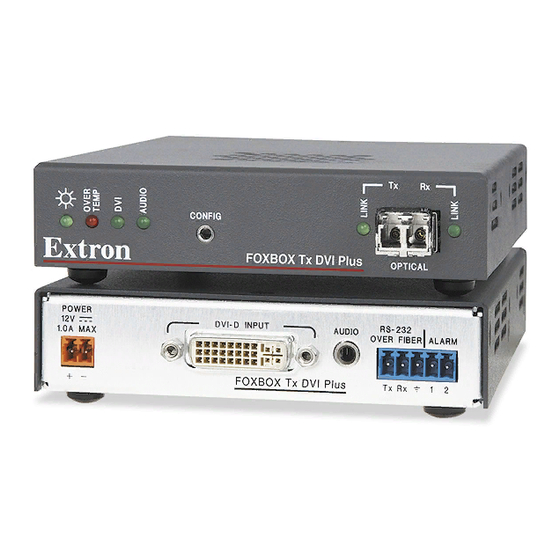
Front Panel OVER FIBER ALARM FOXBOX 4G to pass serial command signals to Figure 2-4 — FOXBOX 4G Tx transmitter’s connectors the receiver, for serial control of a projector for Tx Rx example, connect the host device to the transmitter RGB Input connectors (FOXBOX 4G VGA only) —... -
Page 14: Receiver Connections And Indicators
Tx Rx FOXBOX 4G Rx DVI FOXBOX 4G Rx DVI OPTICAL FOXBOX 4G Rx DVI Rear Panel Front Panel Figure 2-6 — FOXBOX 4G Rx receiver’s connectors FOXBOX 4G Tx/Rx • Installation and Operation FOXBOX 4G Tx/Rx • Installation and Operation... - Page 15 Connect the free end of this fiber optic cable the first three leftmost poles (Tx, Rx, and ) of to the Tx connector on the FOXBOX 4G Tx this 5-pole captive screw connector. See "RS-232 Over Fiber transmitter (item on page 2-8) or to connection"...
-
Page 16: Making Connections
It goes dark if the audio signal drops below the minimum threshold for a short period of time. FOXBOX 4G Tx/Rx • Installation and Operation 2-12 FOXBOX 4G Tx/Rx • Installation and Operation... -
Page 17: Rs-232 Over Fiber Connection
If the stripped section of wire is shorter than 3/16", • wires can be easily pulled out even if tightly fastened by the captive screws. FOXBOX 4G Tx/Rx • Installation and Operation 2-14 FOXBOX 4G Tx/Rx • Installation and Operation 2-15... -
Page 18: Front Panel Configuration Ports
Alternatively, an optional Extron PS 123 Universal 12 VDC Power Supply, part #60-814-01, can power multiple Extron 12 VDC devices using only one AC power connector. FOXBOX 4G Tx/Rx • Installation and Operation 2-16 FOXBOX 4G Tx/Rx • Installation and Operation... -
Page 19: Operation
Configuration port and operate using either SIS commands or the FOX Extender Windows-based control program. See chapter 3, "Remote Control". Chapter Three Remote Control Simple Instruction Set Control Windows -Based Program Control ® FOXBOX 4G Tx/Rx • Installation and Operation 2-18... -
Page 20: Simple Instruction Set Control
= Mode SM = singlemode MM = multimode = Transmitter or receiver Tx = transmitter Rx = receiver = Firmware version v.vv = Internal temperature (Fahrenheit and Celsius) nnnF•nnC FOXBOX 4G Tx/Rx • Remote Control FOXBOX 4G Tx/Rx • Remote Control... -
Page 21: Unit-Initiated Messages
Rx VGA, Vx.xx, 60-934-xx]] E13 - Invalid parameter] - or - E14 - Invalid command for this configuration] (c) COPYRIGHT 2008, EXTRON ELECTRONICS FOXBOX 4G Tx Timeout DVI, Vx.xx, 60-935-xx]] Pauses of 10 seconds or longer between command ASCII - or - characters result in a timeout. -
Page 22: Command/Response Tablefor Sis Commands
Command/response table for SIS commands Command ASCII Command Response Additional description (host to unit) (unit to host) Video mute Mute output Blank the video output. Blk1 Unmute output Output video. Blk0 Show video mute status Video output mute status is (0 = unmuted, 1 = muted). - Page 23 Command/response table for SIS commands (continued) Command ASCII Command Response Additional description (host to unit) (unit to host) Pixel phase N When the controlling PC is connected to the receiver, the FOXBOX 4G can perform this command only if the eceiver Tx to transmitter Rx fiber cable is connected.
- Page 24 Command/response table for SIS commands (continued) Command ASCII Command Response Additional description (host to unit) (unit to host) Audio output level N The FOXBOX 4G receiver outputs audio at the consumer level (-10 dBV) only. Refer to the FOX 500 User's Guide if you are using one of those products to receive the fiber optic signal, as those products can be configured to output audio at the professional level.
- Page 25 Command/response table for SIS commands (continued) Command ASCII Command Response Additional description (host to unit) (unit to host) Information requests X2)] Information request 1Link •2Link •RGB •Aud • • The unit responds with the current status (signal detected) of optical link 1, optical link 2, the video input, the audio input, the fiber optic mode (singlemode or multimode), and the device type (Tx or Rx).
-
Page 26: Windows ® -Based Program Control
FOXBOX receiver in normal configuration (Mode DIP switch 1 down). Figure 3-1 — Communication Setup window FOXBOX 4G Tx/Rx • Remote Control 3-14 FOXBOX 4G Tx/Rx • Remote Control 3-15... -
Page 27: Status Area
FOXBOX 4G model (multimode or singlemode), the internal temperature, and the video input frequency. The "Other Side" entry is the device connected to the far end of the fiber optic cable. FOXBOX 4G Tx/Rx • Remote Control 3-16 FOXBOX 4G Tx/Rx • Remote Control 3-17... -
Page 28: Ddc/Edid Resolution Area
Auto Image button — Click the Auto Image button to adjust the but the program cannot report the position values. output settings for the best image, based on the sensed input resolution. FOXBOX 4G Tx/Rx • Remote Control 3-18 FOXBOX 4G Tx/Rx • Remote Control 3-19... -
Page 29: Audio Adjustment Area
Firmware Loader returns to the top. Valid firmware files must have the file extension “.BIN”. Any other file extension is not a firmware upgrade for your FOXBOX 4G. FOXBOX 4G Tx/Rx • Remote Control 3-20 FOXBOX 4G Tx/Rx • Remote Control 3-21... - Page 30 Click Upload. The File Loader reports, "This process could take several minutes. Please wait..." and then displays the status of the upload. When the Firmware Loader reports, "Transfer complete!", click the Exit button. FOXBOX 4G Tx/Rx • Remote Control 3-22 FOXBOX 4G Tx/Rx • Remote Control 3-23...
-
Page 31: Reference Information
Remote Control, cont’d FOXBOX 4G Tx/Rx A ppendix A Reference Information Specifications Part Numbers FOXBOX 4G Tx/Rx • Remote Control 3-24... -
Page 32: Appendix A • Reference Information
FOXBOX 4G SM Return loss........-40 dB @ 5 MHz Data rate ......... 4.25 Gbps DC offset......... ±5 mV with input at 0 offset Video delay ........1-2 frames FOXBOX 4G Tx/Rx • Reference Information FOXBOX 4G Tx/Rx • Reference Information... - Page 33 Control ........ 9600 baud, 8 data bits, 1 stop bit, no parity Pass-through ...... 9600 to 115200 baud Serial control pin configuration .. Mini stereo jack: tip = Tx, ring = Rx, sleeve = GND FOXBOX 4G Tx/Rx • Reference Information FOXBOX 4G Tx/Rx • Reference Information...
-
Page 34: Part Numbers
(RSU 126, #60-190-10 or RSB 126, #60-604-10) Included parts Furniture mount....Yes, with optional under desk mounting These items are included in each order for a FOXBOX 4G Tx/Rx: kit, (MBU 125, part #70-077-01) Enclosure type ....... Metal Included parts Part number Enclosure dimensions.... -
Page 35: Optional Accessories
HDMI male to male, 6’ (1.8 m) HDMI M-DVI-D M/6 26-614-02 HDMI male to DVI-D male, 6’ (1.8 m) Adapters Accessories Part number HDMIF-DVIDM 26-616-01 HDMI female to DVI-D male adapter HDMIM-DVIDF 26-617-01 HDMI male to DVI-D female adapter FOXBOX 4G Tx/Rx • Reference Information...