
Related Manuals for Mackie SA1532z


Summary of Contents for Mackie SA1532z
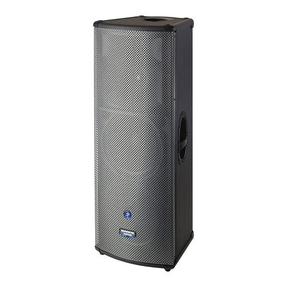
- Page 1 SA1532z REPAIR MANUAL...
-
Page 2: Tools Needed
These instructions are intended to help restore any ailing SA1532z Active Loudspeaker back to factory working conditions. They show how to remove and replace the drivers and the amplifi er assembly. Please contact Mackie Tech Support (1-800-898-3211) to receive a Service Request Number and Order Number for parts needed for this restoration. - Page 3 Led PCB replacement: Carefully begin to remove the grill. Do not fully remove the grill as the cable is still fi rmly attached to the led PCB assembly. A fl at head screwdriver may aid in loosening the grill from the cabinet. Five screws need to be removed from each side of the grill using the phillips head screwdriver (ten screws in all).
- Page 4 Place the new led PCB assembly (part #0007334) where the old one was. Follow the same steps as above, but backwards 6 to 1. Power up the SA1532z and the led should light up. Congratulations, you just replaced an led PCB assembly...now go...
- Page 5 Bottom woofer replacement: Follow steps 1-4 of the led PCB replacement instructions, as the grill will screws 1-5 need to be removed in order to access the bottom woofer. screws 6-8 Keep the eight screws and fl at washers in a safe place. Note: There are two different screws that connect the woofer to the cabinet.
- Page 6 The picture on the right shows what the SA1532z looks like with the grill and bottom woofer removed . Place the new woofer (part #0013917) where the old one was. Follow the same steps as...
- Page 7 Top woofer replacement: Two woofer screws are hidden by the grill Follow steps 1-4 of the led PCB support (outlined on the left). The woofer replacement instructions, as the grill will can not be removed until the support need to be removed in order to access is.
- Page 8 Top woofer replacement continued: Push down The positive (solid yellow) and negative (solid black) cables are still attached to the woofer terminals. Remove the cables from their terminals simply by pushing down on the terminal and pulling out the cable. Keep the eight screws and fl...
- Page 9 . Place the new woofer (part #0013917) where the old one was. Follow the same steps as above, but backwards 6 to 1. Power up the SA1532z and the new woofer should now be pumping out glorious lows. Awesome, you just...
- Page 10 High Frequency Driver replacement: Fourteen screws and washers need to be Follow steps 1-4 of the led PCB removed from the horn assembly using replacement instructions, as the grill will the phillips head screwdriver. need to be removed in order to access the high frequency driver.
- Page 11 High Frequency Driver replacement continued: High Frequency Driver Push down Frequency Driver The positive (solid blue) and negative (blue and black) cables are still attached to the high frequency driver terminals. Remove the cables from their terminals simply by pushing down on the terminal and pulling out the cable.
- Page 12 High Frequency Driver replacement continued: Four screws and locking washers may be removed from the high frequency driver using the phillips head screwdriver. Notice the placement of the terminals, as well. This is what it looks like with the grill and horn removed.
- Page 13 11 to other hand may help. 1. Power up the SA1532z and the new driver should now be pumping out those highs again. Fantastic, you just replaced...
-
Page 14: Diaphragm Replacement
# coming soon) and plate assembly where the old one was. Follow the same steps as above, but backwards 4 to 1. Power up the SA1532z and the new diaphragm should now be pumping out those highs again. Sweet, you just... - Page 15 Mid Frequency Driver replacement: Follow steps 1-6 of the high frequency driver replacement instructions, as the grill and horn assembly will need to be removed in order to access the mid frequency driver. Keep the eight screws and locking washers in a safe place. Eight screws and locking washers may be removed from the mid frequency driver cover plate using the phillips head...
- Page 16 Mid Frequency Driver replacement continued: Pull out Pull out The mid frequency driver cover plate should easily lift right off of the horn. Holding down the horn assembly with one hand while lifting up on the cover plate with the other hand may help.
- Page 17 Replace with the new driver (part #0013897) and follow the same steps as above, but backwards 7 to 1. Power up the SA1532z and the new driver should now be pumping out those mids again. Right on, you just replaced a...
- Page 18 Amplifi er Assembly replacement: Keep the eighteen screws in a safe place. The covers may be worked loose by wedging a fl at head screwdriver in between the cabinet and the cover, as Eighteen screws need to be removed well as the amplifi er assembly and cover. from the amplifi...
- Page 19 Amplifi er assembly replacement continued: The amplifi er assembly is now ready to be separated from the cabinet. Do not completely take the amplifi er assembly off yet, as seven cables need to be removed fi rst (as shown above): (1) led PCB cable, (2) solid yellow, (3) solid black, (4) blue and black, (5) solid blue, (6) green and black, and...
- Page 20 Amplifi er assembly replacement continued: Edge of amplifi er assembly Edge of amplifi er assembly Closeups of the led PCB cable and Now for the closeups of the woofer and connector are shown above. The black driver terminals. Make sure the cables wire of the cable is closest to the ribbon are reconnected to the same terminals cable.
- Page 21 (as shown in picture above) and place on the new amplifi er assembly. Power up the SA1532z and relish in the fact that you just replaced an amplifi er assembly. Hats off to you for...