Table of Contents
Advertisement
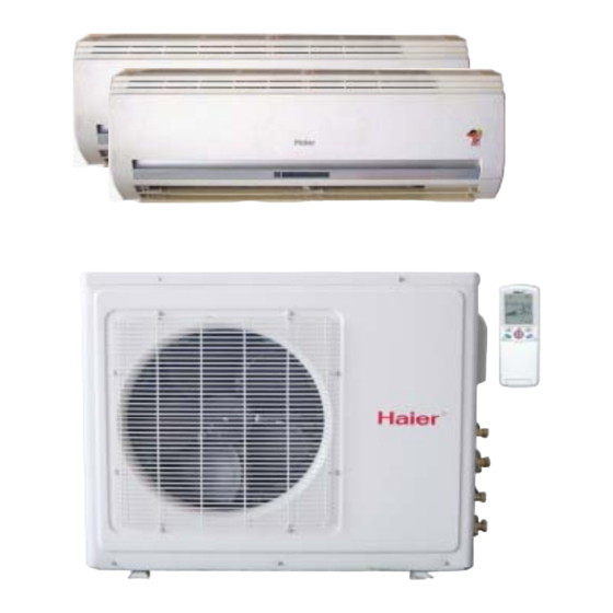
Air Conditioner
Edition:2006/1/10
CAUTION
READ THIS MANUAL CAREFULLY TO
DIAGNOSE TROUBLE CORRECTLY
BEFORE OFFERING SERVICE .
SERVICE MANUAL
Air Conditioners
MODEL: H2SM-(9+12)HV03/R2(DB)
H2SM-(9+9)HV03/R2(DB)
THIS MANUAL IS USED BY
QUALIFIED APPLIANCE
TECHNICIANS ONLY. HAIER
DOES NOT ASSUME ANY
RESPONSIBILITY FOR PROPERTY
DAMAGE OR PERSONAL INJURY
FOR IMPROPER SERVICE
PROCEDURES DONE BY ONE
UNQUALIFIED PERSON.
REVISION 0
Advertisement
Table of Contents

Related Manuals for Haier H2SM-(9+12)HV03/R2


Summary of Contents for Haier H2SM-(9+12)HV03/R2
-
Page 1: Service Manual
Edition:2006/1/10 CAUTION READ THIS MANUAL CAREFULLY TO DIAGNOSE TROUBLE CORRECTLY BEFORE OFFERING SERVICE . SERVICE MANUAL Air Conditioners MODEL: H2SM-(9+12)HV03/R2(DB) H2SM-(9+9)HV03/R2(DB) THIS MANUAL IS USED BY QUALIFIED APPLIANCE TECHNICIANS ONLY. HAIER DOES NOT ASSUME ANY RESPONSIBILITY FOR PROPERTY DAMAGE OR PERSONAL INJURY... -
Page 2: Important Information
Air Conditioner Edition:2006/1/10 MODEL: H2SM-(9+12)HV03/R2(DB) IMPORTANT INFORMATION Features Comfortable: wide-angle airflow health air purifying quiet operation super energy efficient Main Specification 2600/3500/5300W Cooling Capacity Rated Power/Current(cooling) 680/990/1600W/7.8A EER: 3.8/3.5/3.3W/W 3200/3800/6600W Heating Capacity Rated Power/Current(heating): 1185/1455/1930W/9.2A COP: 2.7/2.6/3.4W/W Air Volume(Indoor): 500/550m... - Page 3 Air Conditioner Edition:2006/1/10 MODEL: H2SM-(9+9)HV03/R2(DB) IMPORTANT INFORMATION Features Comfortable: wide-angle airflow health air purifying quiet operation super energy efficient Main Specification 2600/5200W Cooling Capacity Rated Power/Current(cooling) 680/1520W/7.5A EER: 3.8/3.29W/W 3200/6500W Heating Capacity Rated Power/Current(heating): 1185/1880W/8.8A COP: 2.8/3.2W/W Air Volume(Indoor): 500m Power: 1PH 220-230V~ 50 Hz...
-
Page 4: Safety Information
Haier urges you read and follow all safety precautions and warnings contained in this manual. Failure to comply with safety information may result in severe personal injury or death. -
Page 5: Table Of Contents
Air Conditioner Edition:2006/1/10 CONTENTS 1. SPECIFICATION........1 2. ACCESSORIES........4 3. OPERATION........7 4. ELECTRICAL CONTROLL......33 5. TROUBLE SHOOTING.........5 0 6. INSTALLA TION........56 7. CIRCUIT AND WIRING DIAGRAM.......64... -
Page 6: Specification
Air Conditioner Edition:2006/1/10 SPECIFICATION... - Page 7 Air Conditioner Edition:2006/1/10 H2SM-(9+12)HV03/R2(DB) ----- Model Brand Mark Cooling Capacity : 2600/3500/5300(1300-6100)W 50Hz Frequency Range Rated Power/Current : 680/990/1600(380-2400)W/7.8A 220-230V~ 50 Hz Power Cooling 2530W/10.3A -------- Max Power/Current Model×Sectional Area EE R 3.8/3.5/3.3W/W Power Cord Heating Capacity : 3200/3800/6600(1720-6960)W Refer. No.
- Page 8 Air Conditioner Edition:2006/1/10 H2SM-(9+9)HV03/R2(DB) ----- Model Brand Mark Cooling Capacity : 2600/5200(1250-6000)W 50Hz Frequency Range Rated Power/Current : 680/1520(360-2300)W/7.5A 220-230V~ 50 Hz Power Cooling 2490W/10.2A -------- Max Power/Current Model×Sectional Area EE R 3.8/3.29W/W Power Cord 3200/6500(1620-6800)W Heating Capacity Refer. No. -------- SANYO Compressor...
-
Page 9: Accessories
Air Conditioner Edition:2005/11/18 ACCESSORIES... - Page 10 Edition:2006/1/10 Air Conditioner H2SM-(9+12)HV03/R2(DB) Failure Number Name Refer No. Description Quality Remark Rate(%) remote 0010403792 None controller battery 001A4600001 None Fix mounting plate mounting according to 0010101274 plate installation position and pipe direction Choose the place that can drain drain pipe...
- Page 11 Edition:2006/1/10 Air Conditioner H2SM-(9+9)HV03/R2(DB) Failure Number Name Refer No. Description Quality Remark Rate(%) remote 0010403792 None controller battery 001A4600001 None Fix mounting plate mounting according to 0010101274 plate installation position and pipe direction Choose the place that can drain drain pipe 001A0900011 water and connect pipe easily...
- Page 12 Air Conditioner Edition:2005/11/18 OPERRATION...
- Page 13 Air Conditioner Edition:2006/1/10 Cautions Disposal of the old air conditioner Safety Instructions and Warnings Before starting the air conditioner, read the Before disposing an old air conditioner that information given in the User's Guide caref- goes out of use, please make sure it's inop- ully.
- Page 14 Air Conditioner Edition:2006/1/10 Cautions Do not obstruct or cover the ventilation 8. Young children should be supervised grille of the air conditoner.Do not put fingers to ensure that they do not play with or any other things into the inlet/outlet and the applience.
-
Page 15: Safety Instruction
Air Conditioner Edition:2006/1/10 Cautions Safety Instruction Please read the following Safety Instructions carefully prior to use. The instructions are classified into two levels, WARNING and CAUTION according to the seriousness of possible risks and damages as follows. Compliance to the instructions are strictly required for safety use. - Page 16 Air Conditioner Edition:2006/1/10 Cautions WARNING When abnormality such as burnt-small found, Use an exclusive power source with a immediately stop the operation button and circuit breaker contact sales shop. STRICT ENFORCEMENT Connect power supply cord Use the proper voltage Do not use power supply cord to the outlet completely extended or connected in halfway STRICT...
-
Page 17: Parts And Functions
Air Conditioner Edition:2006/1/10 Parts and Functions Indoor unit Outlet Display board Air filter(inside) Inlet Air Purifying Filter (inside) Inlet grille Anion generator (inside) Vertical flap (adjust up and down air flow. Don't adjust it manually) Horizontal louver (adjust left and right air flow) For multi-split type, the power plug is on the outdoor unit Outdoor unit OUTLET... - Page 18 Air Conditioner Edition:2006/1/10 Parts and Functions 11. TIMER ON display 12. FAN SPEED display AUTO 13. LOCK display 14. SWING UP/DOWN display 15. SLEEP display FRESH 16. HEALTH display 17.FRESH AIR display 18. Operation mode display POWER/SOFT Operation mode AUTO COOL DRY HEAT FAN Remote controller...
- Page 19 Air Conditioner Edition:2006/1/10 Parts and Functions Clock Set When unit is started for the first time and after replacing batteries in remote controller, clock should be adjusted as follows: FRESH 1. Press CLOCK button,"AM" or "PM" flashes. 2. Press to set correct time. Each press will increase or decrease POWER/SOFT 1 min.
-
Page 20: Operation
Air Conditioner Edition:2006/1/10 Operation HEALTH operation Remote controller 1.Unit start Press ON/OFF on the remote controller, unit starts. 2.Health anion function Press HEALTH button. For each press, is displayed. Air conditioner starts health anion function operation. For twice press, disappears,the operation stops. When indoor fan motor is running, it has healthy process function. -
Page 21: Auto Operation
Air Conditioner Edition:2006/1/10 Operation Auto Operation 1. Unit start Remote controller Press ON/OFF on the remote controller, unit starts. 2.Select operation mode Press MODE button. For each press, operation mode changes as follows: Remote controller: AUTO COOL HEAT Then Select Auto operation On the displaying board,colorful displaying bar will be white. -
Page 22: Cool Operation
Air Conditioner Edition:2006/1/10 Operation Cool Operation 1. Unit start Press ON/OFF on the remote controller, unit starts. Remote controller 2.Select operation mode Press MODE button. For each press, operation mode changes as follows: Remote controller: AUTO COOL HEAT Then Select COOL operation On the displaying board,colorful displaying bar will be blue. -
Page 23: Dry Operation
Air Conditioner Edition:2006/1/10 Operation Dry Operation 1. Unit start Press ON/OFF on the remote controller, unit starts. Remote controller 2.Select operation mode Press MODE button. For each press, operation mode changes as follows: Remote controller: AUTO COOL HEAT Then Select DRY operation On the displaying board,colorful displaying bar will be light blue 3.Select temp.setting... -
Page 24: Fan Operation
Air Conditioner Edition:2006/1/10 Operation Fan Operation 1. Unit start Press ON/OFF on the remote controller, unit starts. Remote controller 2.Select operation mode Press MODE button. For each press, operation mode changes as follows: Remote controller: AUTO COOL HEAT Then Select FAN operation On the displaying board,colorful displaying bar will be pink. -
Page 25: Heat Operation
Air Conditioner Edition:2006/1/10 Operation Heat Operation 1. Unit start Remote controller Press ON/OFF on the remote controller, unit starts. 2.Select operation mode Press MODE button. For each press, operation mode changes as follows: Remote controller: AUTO COOL HEAT Then Select HEAT operation On the displaying board,colorful displaying bar will be red 3.Select temp.setting Press TEMP. -
Page 26: Air Flow Direction Adjustment
Air Conditioner Edition:2006/1/10 Operation Air Flow Direction Adjustment 1.Status display of air sending Vertical flap Horizontal louvers Pos.1 Pos.1 Pos.2 Pos.2 Pos.3 Pos.3 Pos.4 Pos.4 FRESH Pos.5 Pos.5 POWER/SOFT Pos.6 Pos.6 (Auto swing) Pos.7 Pos.8 2.Up and down air flow direction For each press of button, air flow direction on remote controller displays as follows according to different operation modes:... -
Page 27: Sleep Operation
Air Conditioner Edition:2006/1/10 Operation Sleep Operation SLEEP operation starts SLEEP operation stops Approx.6hrs Before going to bed, you can simply press the Rises 1 SLEEP button and unit will operate in SLEEP 1 hr mode and bring you a sound sleep. Rises 1 1 hr Use of SLEEP function... -
Page 28: Timer On/Off Operation
Air Conditioner Edition:2006/1/10 Operation Timer On/Off Operation Set clock correctly before starting TIMER operation. Remote Controller 1. After unit starts, select your desired operation mode Operation mode will be displayed on LCD. 2. Timer mode selection Press TIMER button to change TIMER mode. Every time the button is pressed, display changes as follows: Remote controller: BLANK... - Page 29 Air Conditioner Edition:2006/1/10 Operation Timer On-Off Operation Set clock correctly before starting TIMER operation. 1. After unit starts, select your desired operation mode Operation mode will be displayed on LCD. Remote Controller 2. Timer mode selection Press TIMER button to change TIMER mode. Every time the button is pressed, display changes as follows: Remote controller: BLANK...
-
Page 30: Power/Soft Operation
Air Conditioner Edition:2006/1/10 Operation POWER/SOFT Operation POWER Operation When you need rapid heating or cooling, you can use this funciton. Selecting of POWER operation Press POWER/SOFT button. Every time the button is pressed,display changes as follows: BLANK POWER SOFT Stop the display at In POWER operation status: In HEAT or COOL mode, fan speed automatically runs in HI mode for 15 min then returns to original status setting. -
Page 31: Health Airflow Operation
Air Conditioner Edition:2006/1/10 Operation Health airflow Operation 1.Press ON/OFF to starting The liquid crystal will display the working state of last time Remote controller (Except timer, sleeping, power/soft and health airflow). Setting the comfort work conditions. 2.The setting of health airflow function 1).Press the button of health airflow, appears on the display. -
Page 32: Emergency And Test Operation
Air Conditioner Edition:2006/1/10 Operation Emergency and Test Operation Emergency operation: Use this operation only when the remote controller is defective or lost. When the emergency operation switch is pressed,the" Pi "sound is heard once, which means the start of this operation. In this operation, the system automatically selects the operation modes, cooling or heating, according to the room temperature. - Page 33 Air Conditioner Edition:2006/1/10 Maintenance For Smart Use of The Air Conditioner Setting of proper room Do not block the air inlet temperature or outlet Proper temperature Close doors and windows Use the timer effectively during operation During cooling operation prevent the penetration of direct sunlight with curtain or blind Use the louvers effectively...
-
Page 34: Air Filter Cleaning
Air Conditioner Edition:2006/1/10 Maintenance For Smart Use of The Air Conditioner WARNING Before maintenance,be sure to turn off the system and the circuit breaker. Remote Controller Indoor Body Wipe the air conditioner by using a soft and dry cloth.For serious stains,use a neutral Do not use water, wipe the controller with a detergent diluted with water.Wring the water dry cloth.Do not use glass cleaner or chemical... - Page 35 Air Conditioner Edition:2006/1/10 Maintenance Replancement of Air Purifying Filter 1.Open the lnlet Grille Open the inlet grille by pushing each ends of the inlet grille upward.(use thumbs to push 2.Detach the standard air filter Slide the knob slightly upward to release the filter, then withdraw it.
- Page 36 Air Conditioner Edition:2006/1/10 Maintenance To Keep Your Air conditioner in Good Condition after Season. Operate in cooling mode for 2-3 hours. To prevent breeding mold or bad smell, be sure to operate at the designated temperature or 30 C,cooling mode and High speed fan mode for 2-3 hours. Put off the power supply cord.
-
Page 37: Cleaning The Standard Air Filter
Air Conditioner Edition:2006/1/10 Maintenance Before Setting in High season Cleaning the standard air filter. Operation without filter may cause troubles.Be sure to attach both right and left filters prior to the operation. Each of them are of different shapes. Connecting the earthing cable. Caution Incomplete earthing may cause an electric shock. -
Page 38: Electrical Controll
Air Conditioner Edition:2005/11/18 ELECTRICAL CONTROLL... - Page 39 Edition:2006/1/10 Air Conditioner 1. Operation Mode 1. Automatic operation When the system is under the automatic operation option, the appropriate operation mode will be decided according to the differences between the preset temperature and the indoor temperature after the system starts up. Then, the system will operate according to the chosen mode. In the following conditions, Tr stands for indoor temperature and Ts stands for outdoor temperature.
- Page 40 Edition:2006/1/10 Air Conditioner be stopped and the malfunction will be recorded in the malfunction list. The indoor system will continue to run. When the temperature of the indoor coil is raised to 7¡ æ , the compressor will be restarted again (the prerequirement of 3 minutes¡ ¯ delay should be satisfied.) * timing system on/off function.
- Page 41 Edition:2006/1/10 Air Conditioner 4. Heating operation mode. * temperature control range: 16---30¡ æ ±1¡ æ * temperature difference: * control feature: the temperature compensation is automatically added and the system will send the heating signals to the outdoor system. If Tr≤Ts, the outdoor compressor is turned on, the indoor fan will be at the cold air proof mode.
- Page 42 Edition:2006/1/10 Air Conditioner Coldair proof operation 1. The indoor operation within 4 minutes after the start up is as the following diagram, the air speed can be raised only after the speed has reached a certain level. Set speed Heat start temp 1 Keep the high Heat start temp speed.
- Page 43 Edition:2006/1/10 Air Conditioner 3. Soft operation the system enters the mode after receiving the ¡ ® soft signal¡ ¯ . a. soft heating: the airflow speed is slight, the system sends the soft signal to the outdoor system. b. soft cooling: the airflow speed is slight, the system sends the soft signal to the outdoor system. When the compressor operates, the airflow speed is soft speed.
- Page 44 Edition:2006/1/10 Air Conditioner the setting. If the fan is at the medium speed before the sleep setting, the speed will be turned to low after the setting. If the fan is at the low speed before the sleep setting, the speed will not change. 7.
- Page 45 Edition:2006/1/10 Air Conditioner operation malfunction will be reported. 30s after the report, the indoor system will be closed. Outdoor system mode Indoor system mode conflicts cooling heating cooling cooling cooling airflow heating heating heating airflow heating cooling The last malfunction list resume. Nothing is presented if there is no code list.
- Page 46 Edition:2006/1/10 Air Conditioner as the followings: Remote control urgency singal: operate according to the remote control and the urgent conditions, the present status will be stored into the EEPROM of the indoor system. * Quitting conditions: Press dormant button 10 times within 7 seconds and the buzzer will ring twice. 14£...
- Page 47 Edition:2006/1/10 Air Conditioner Appendix 1 The malfunction code for the indoor and outdoor system interaction malfunctions. Sample: ■ the led off □ the led on ★ the led flashing Indoor system malfunction codes HS series malfunctio malfunction HV series n codes heating cooling operation Indoor...
- Page 48 Edition:2006/1/10 Air Conditioner outdoor system malfunction code(the indoor unit can show you some malfunction code, as follow) HS series malfunctio malfunction HV series n codes heating cooling operation Ambient sensors circuit break □ ★ ■ Hot temperature sensor circuit breaks or ★...
- Page 49 Edition:2006/1/10 Air Conditioner OUTDOOR SYSTEM FUNCTIONS The outdoor system will decide the operation mode based on the principle of ¡ ® first order preferred¡ ¯ according to the startup signals of the two indoor systems. a) cooling: Under the cooling operation, the four direction latch will not be closed. The outdoor fan will operate at the cooling mode.
- Page 50 Edition:2006/1/10 Air Conditioner When the outdoor speed is M or L, the speed will change according to the heat interaction temperature. The status will be checked every minute. Ta>28¡ æ £ ¬ high speed 26¡æ<Ta<28¡æ £¬high/ low speed Ta<26¡ æ £ º Te¨R40¡æ£¬high speed 37¡æ¨QTe<40¡æ£¬high/ medium speed 35¡æ¨QTe...
- Page 51 Edition:2006/1/10 Air Conditioner i) The outdoor fixed frequency is set according to the indoor system signals. The operation is on the frequency stored in EEPROM ii) The cooling and heating value under the double system operation Under the single system fixed frequency test, the outdoor system will operate according to the turned-on indoor system status.
- Page 52 Edition:2006/1/10 Air Conditioner After the stopping of the system, the flashing time of the LED02 is the malfunction code. For example£ º Malfunction N.O 4 2.5sec 2.5sec Ambient sensors circuit break. Hot temperature sensor circuit breaks or shorts. Outlet temperature sensor circuit breaks or shorts. DC compressor feedback.
- Page 53 Edition:2006/1/10 Air Conditioner D501-D504 on the main board with a multimeter. Test if there is any 5v circuit shorts at R501-R503 and D-505. Replace device CT501. 7#. No load: Test the 4 diodes D501-D504 on the main board with a multimeter. Test is there is any circuit short with GND at R501-R503 and D505( special focus on the possible circuit short condition the terminal A of D502 and terminal K of D504).
- Page 54 Air Conditioner Edition:2005/11/18 TROUBLE SHOOTING...
-
Page 55: Trouble Shooting
2006/1/10 Air Conditioner Trouble shooting Before asking for service, check the following first. Phenomenon Cause or check points The system does not restart When unit is stopped, it won't restart immediately until 3 minutes have elapsed immediately. to protect the system. When the electric plug is pulled out and reinserted, the protection circuit will work for 3 minutes to protect the air conditioner. - Page 56 Air Conditioner Edition:2006/1/10 Abnormality Diagnosing Trouble Parts that may appear problems Prepared parts Applicable Number Description phenomenon and the Cause and tools machine 7805,transformer, piezo Use the resistance, fuse,remote controller, 7805,transfor remote receiver. If it can be booted by mer, fuse, controller to using manual emergency switch, piezo...
- Page 57 Air Conditioner Edition:2006/1/10 Drain pan, drain hose. Check Oriented whether the indoor unit is installed wind panel horizontal, drain hose of indoor invariable Indoor unit or drain drain pan, unit is leveled off ,the hole is over frequency make water pan makes drain hose high...
- Page 58 Air Conditioner Edition:2006/1/10 Outdoor P.C. Board 4 way valve coil 4 way valve body. Examine The air the CN204 at Outdoor P.C. Board Outdoor P.C. conditioner and watch if there is 220V Board 4way Little split Don’t make voltage .If there doesn’t have we valve coil unit of heat...
-
Page 59: Installation
Air Conditioner Edition:2005/11/18 INSTALLATION... -
Page 60: Installation Manual Of Room Air Conditioner
Air Conditioner Edition:2006/1/10 Installation Manual of Room Air Conditioner Read this manual before installation Explain sufficiently the operating means to the user according to this manual. Necessary Tools for Installation 1.Driver 5.Torque wrench(17mm,22mm,26mm) 9.Nipper 12.Reamer 2.Hacksaw 6.Pipe cutter 10.Gas leakage detector or 3.Hole core drill 7.Flaring tool soap-and-water solution... - Page 61 Air Conditioner Edition:2006/1/10 113.5 113.5 Floor fixing dimensions of the outdoor unit (Unit:mm) Fix the unit to concrete or block with bolts( 10mm) and nuts firmly and horizontally. Fixing of outdoor unit When fitting the unit to wall surface, roof or rooftop, fix a supporter surely with nails or wires in consideration of earthquake and strong wind.
-
Page 62: Installation Of The Indoor Unit
Air Conditioner Edition:2006/1/10 Indoor unit 1.Fitting of the Mounting Plate and Positioning of the wall Hole When the mounting plate is first fixed 1.Carry out, based on the neighboring pillars or lintels, a proper leveling for the plate to be fixed against the wall, then temporarily fasten the plate with one steel nail. - Page 63 Air Conditioner Edition:2006/1/10 Indoor unit Heat insulation Piping material Lid for right piping Pipe supporting plate Lid for left piping Drain hose Lid for under piping Indoor/outdoor electric cable Fix with adhesive tape Indoor/outdoor electric cable and drain hose must be bound with refrigerant piping by protecting tape. [Other direction piping] Cut away, with a nipper, the lid for piping according to the piping direction and then bend the pipe according to the position of wall hole.
- Page 64 4G0.75mm 4G0.75mm YEL/GRN YEL/GRN Indoor unit B Indoor unit B H2SM-(9+9)HV03/R2(DB) YEL/GRN H2SM-18HV03/R2 H2SM-(9+12)HV03/R2(DB) YEL/GRN Outdoor unit H2SM-(9+12)HV03/R2 Outdoor unit Power cable: 3G4.0mm 5.Easily-demount cleaning of indoor unit claw of the clip 1.Top inlet can be taken down Open the inlet grille, press the claw of the clip on the unit,then take down the top inlet.(according to figure 1)
-
Page 65: Installation Of Outdoor Unit
Air Conditioner Edition:2006/1/10 Outdoor unit 1.Installation of Outdoor Unit Drawing for the installation of indoor and outdoor units Install according to 2.Connection of pipes To bend a pipe, give the roundness as large as possible not to crush the pipe ,and the bending radius should be 30 to 40 mm or longer. - Page 66 Air Conditioner Edition:2006/1/10 Outdoor unit 2-way valve Liquid Side 6.Purging Method:To use vacuum pump 3-way valve Gas Side Detach the service port's cap of 3-way valve, the Gaugemanifold(for R410A) valve rod's cap for 2-way valve and 3-way's, connect Anti countercurrent joint the service port into the projection of charge hose (Iow) for gaugemanifold.
- Page 67 Air Conditioner Edition:2006/1/10 1.Power Source Installation The power source must be exclusively used for air conditioner. (Over I0A) In the case of installing an air conditioner in a moist place, please install an earth leakage breaker. For installation in other places, use a circuit breaker as far as possible. 2.Cutting and Flaring Work of Piping Pipe cutting is carried out with a pipe cutter and burs must be removed.
-
Page 68: Circuit And Wiring Diagram
Air Conditioner Edition:2005/11/18 CIRCUIT AND WIRING DIAGRAM... - Page 69 Air Conditioner Edition:2006/1/10 H2SM-(9+12)HV03/R2(DB) INDOORS CIRCUIT DIAGRAM H2SM-(9+9)HV03/R2(DB) +12v BEEP-PKM13EPY-4002 DB-41-23-T BUZZ 104/50v S9013 S9013 +12v 1N4007 7805 CN12 103/50V LB2271 104/50V 470U/25V 103/50V 2200U/25V R12 1K 2SC2412 2SC2412 4.7k +12V 220V-N CON12 2SC2412 103/50v R6627 R2710K 2SC2412 S14K350 474/275V...
- Page 70 Edition:2006/1/10 Air Conditioner OUTDOORS CIRCUIT DIAGRAM H2SM-(9+12)H03/R2(DB) H2SM-(9+12)HV03/R2(DB) H2SM-(9+9)HV03/R2(DB) IC08 TD62003 IC04 FAN H 7805 1K/1/4W L201 10K/1/4W FAN M Vout 330uH 10K/1/4W CN01 FAN L CN07 1K/1/4W CN201 SELFCHECK ALARM RL01 R208 LED01 JQ1a-12V VALVE 10K/1/4W PIPEB T 1K/1/4W...
- Page 71 Edition:2006/1/10 Air Conditioner H2SM-(9+12)HV03/R2(DB) INDOORS WIRING DIAGRAM H2SM-(9+9)HV03/R2(DB) BLACK WHITE YELLOW/GREEN...
- Page 72 Edition:2006/1/10 Air Conditioner H2SM-(9+12)HV03/R2(DB) OUTDOORS WIRING DIAGRAM H2SM-(9+9)HV03/R2(DB) OUTDOORS WIRING DIAGRAM 0010556999 PFC REACTOR DON'T TOUCH CAPACITOR, EVEN AFTER PLUG-OFF ( DANGER OF ELECTRIC SHOCK) The capacitor retains high P2(DCOUT-) CAPACITOR P5(L) P6(L) voltage even after the plug-off. 2500uF/400V For your safety, be sure to wait at least 5 minutes.
- Page 73 Air Conditioner Edition:2006/1/10 Sincere Forever Haier Group Haier Industrial Park, No.1, Haier Road 266101, Qingdao, China http://www.haier.com...