
Related Manuals for Delta 40-650


Summary of Contents for Delta 40-650
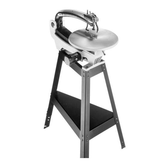
- Page 1 18" Variable Speed Scroll Saw (Model 40-650, Type 2) Quick Quality Quiet PART NO. 1349463 DATED 11-25-98 © Delta International Machinery Corp. 1998...
-
Page 2: Table Of Contents
TABLE OF CONTENTS SAFETY RULES..........................3 ADDITIONAL SAFETY RULES FOR SCROLL SAWS ................4 UNPACKING AND CLEANING ......................5-6 ASSEMBLY INSTRUCTIONS......................6 Assembling Stand ..........................6 Fastening Scroll Saw To Stand ......................7 Assembling Rear Leg Height Extension ....................8 Assembling Holddown Foot ......................8 Rotating Table To 90 Degree Position ....................8 Assembling Table Insert ........................8 CONNECTING SCROLL SAW TO POWER SOURCE ................9 Extension Cords ..........................9... -
Page 4: Safety Rules
ADDITIONAL SAFETY RULES FOR SCROLL SAWS 1. WARNING: Do not operate your scroll saw until it is Only feed the material fast enough so that the blade will completely assembled and installed according to the cut. instructions. 20. NEVER start the Scroll Saw with the stock pressed 2. -
Page 5: Unpacking And Cleaning
UNPACKING AND CLEANING Your new scroll saw and stand is shipped complete in one container. Carefully unpack the saw, stand and all loose items from the shipping container. Figure 2 illustrates the saw and all loose items and Figure 3 illustrates the stand and all related parts. -
Page 6: Assembly Instructions
Fig. 3 20 - Height Adjustment Bracket for rear leg 15 - Bottom Shelf 21 - Flat Washers (28) 16 - Legs (3) 22 - 5/8" long (8mm) Carriage Bolts (28) 17 - Left Top Brace 23 - Hex Nuts (28) 18 - Right Top Brace 19 - Front Top Brace ASSEMBLY INSTRUCTIONS... -
Page 7: Fastening Scroll Saw To Stand
FASTENING SCROLL SAW TO STAND 1. Place scroll saw on top braces of stand and fasten front of saw to top front brace using the two 1-1/2" long screws (A) Fig. 5, flat washers (B) and two flat washers (C), lock washers (D) and hex nuts (E) from below. -
Page 8: Assembling Rear Leg Height Extension
ASSEMBLING REAR LEG HEIGHT EXTENSION 1. A height extension (A) Fig. 9, is supplied with your stand and can be assembled to the rear leg of the stand, as shown, using the four carriage bolts (B), flat washers and nuts sup- plied. -
Page 9: Connecting Scroll Saw To Power Source
CONNECTING SCROLL SAW TO POWER SOURCE IMPORTANT: BEFORE CONNECTING THE SAW TO THE POWER LINE, MAKE SURE THE SWITCH IS IN THE “OFF” POSITION. EXTENSION CORDS EXTENSION CORD SIZE The use of any extension cord will cause some loss of power. -
Page 10: Fastening Stand To Supporting Surface
IMPORTANT: We suggest that when the scroll saw is not in use, the on-off switch be locked in the “OFF” position using a padlock (A), as shown in Fig. 17. Available as an accessory from Delta is the 50-325 padlock, shown at (A). Fig. 17... -
Page 11: Dust Blower
DUST BLOWER A dust blower (A) Fig. 18, is provided, and can be moved to direct air to the most effective point on the cutting line. Fig. 18 Fig. 19 Fig. 20 ADJUSTING BLADE TENSION Tension is applied to the blade when the blade tension lever (A) Fig. 19, is in the rear position, as shown. -
Page 12: Adjusting Clamping Action Of Blade Holders
ADJUSTING CLAMPING ACTION OF BLADE HOLDERS Different widths of scroll saw blades will make it necessary to adjust the clamping action of the blade holders. It should be noted, however, that very little adjustment is necessary and very little clamping force is required to hold the blade satisfactorily. -
Page 13: Changing Blades
CHANGING BLADES 1. WARNING: TO AVOID INJURY FROM ACCIDENTAL STARTING, ALWAYS TURN SWITCH “OFF” AND RE- MOVE POWER CORD PLUG FROM ELECTRICAL OUT- LET BEFORE REMOVING OR REPLACING BLADE. 2. Remove table insert (A) Fig. 24, and release blade tension by pulling tension lever (B) forward, as shown. Fig. -
Page 14: Tilting The Table
TILTING THE TABLE 1. The table on your scroll saw can be tilted up to 45 degrees to the right for bevel cutting operations by loos- ening table lock handle (A) Fig. 27. Tilt the table to the desired angle and tighten lock handle (A). A scale and pointer (B) Fig. -
Page 15: Aligning Lower Blade Holder With Upper Blade Holder
ALIGNING LOWER BLADE HOLDER WITH UPPER BLADE HOLDER The lower blade holder has been aligned with the upper blade holder at the factory and fur- ther alignment should not be necessary; how- ever, to check or adjust the alignment, pro- ceed as follows: 1. -
Page 16: Fuse Replacement
FUSE REPLACEMENT A fuse holder (A) Fig. 36, and fuse (B) are located up under the rear of the machine and should be removed and checked if the machine does not operate. If the fuse (B) is bad, replace it with a 4 amp fuse. Fig.