
Related Manuals for Hobart AIRFORCE 700I


Summary of Contents for Hobart AIRFORCE 700I
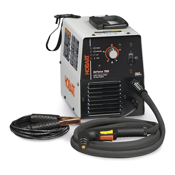
- Page 1 OM-244 013C 2010-04 Processes Air Plasma Cutting Description Air Plasma Cutter AirForce 700i ™ And HP-70 Torch File: Plasma Cutters...
- Page 2 From Miller to You Thank you and congratulations on choosing Miller. Now you can get the job done and get it done right. We know you don’t have time to do it any other way. That’s why when Niels Miller first started building arc welders in 1929, he made sure his products offered long-lasting value and superior quality.
-
Page 3: Table Of Contents
TABLE OF CONTENTS SECTION 1 ï SAFETY PRECAUTIONS - READ BEFORE USING 1-1. Symbol Usage ............... . 1-2. -
Page 5: Section 1 Ï Safety Precautions - Read Before Using
SECTION 1 ï SAFETY PRECAUTIONS - READ BEFORE USING Protect yourself and others from injury — read and follow these precautions. 1-1. Symbol Usage DANGER! ï Indicates a hazardous situation which, if not avoided, will result in death or serious injury. The possible hazards are shown in the adjoining symbols or explained in the text. -
Page 6: Electric Shock Can Kill
ELECTRIC SHOCK can kill. SIGNIFICANT DC VOLTAGE exists in inverter power sources AFTER the re- moval of input power. D Turn Off unit, disconnect input power, check voltage on input ca- pacitors, and be sure it is near zero (0) volts before touching any parts. -
Page 7: Additional Symbols For Installation, Operation, And Maintenance
1-3. Additional Symbols For Installation, Operation, And Maintenance HOT PARTS can burn. D Do not touch hot parts bare handed. D Allow cooling period before working on equipment. D To handle hot parts, use proper tools and/or wear heavy, insulated welding gloves and clothing to prevent burns. -
Page 8: California Proposition 65 Warnings
1-4. California Proposition 65 Warnings Welding or cutting equipment produces fumes or gases which contain chemicals known to the State of California to cause birth defects and, in some cases, cancer. (California Health & Safety Code Section 25249.5 et seq.) Battery posts, terminals and related accessories contain lead and lead compounds, chemicals known to the State of California to cause cancer and birth defects or other... -
Page 9: Section 2 Ï Consignes De Sécurité Ï Lire Avant Utilisation
SECTION 2 ï CONSIGNES DE SÉCURITÉ ï LIRE AVANT Se protéger et protéger les autres contre le risque de blessure — lire et respecter ces consignes. 2-1. Signification des symboles DANGER! ï Indique une situation dangereuse qui si on l’évite pas peut donner la mort ou des blessures graves. Les dangers possibles sont montrés par les symboles joints ou sont expliqués dans le texte. - Page 10 D Assurezïvous que le fil de terre du cordon d’alimentation est cor- rectement relié à la borne de terre dans la boîte de coupure ou que la fiche du cordon est branchée à une prise correctement mise à la terre ï vous devez toujours vérifier la mise à la terre. D Avant d’effectuer les connexions d’alimentation, vous devez relier le bon fil de terre.
-
Page 11: Dangers Supplémentaires En Relation Avec L'installation, Le Fonctionnement Et La Maintenance
D Ne coupez pas dans un endroit près d’opérations de décapage, de nettoyage ou de vaporisation. La chaleur et les rayons d’arc peu- vent réagir avec les vapeurs et former des gaz hautement toxiques et irritants. D Ne coupez pas des métaux enrobés tels que des métaux galvani- sés, contenant du plomb ou de l’acier plaqué... - Page 12 Les CHAMPS ÉLECTROMAGNÉTIQUES (CEM) peuvent affecter les implants médicaux. D Les porteurs de stimulateurs cardiaques et autres implants médicaux doivent rester à distance. D Les porteurs d’implants médicaux leur médecin et le fabricant du dispositif avant de s’approcher de la zone où se déroule du soudage à l’arc, du soudage points, gougeage, ou une opération de chauffage par induction.
-
Page 13: Proposition Californienne 65 Avertissements
2-4. Proposition californienne 65 Avertissements Les équipements de soudage et de coupage produisent des fumées et des gaz qui contiennent des produits chimiques dont l’État de Californie reconnaît qu’ils provoquent des mal- formations congénitales et, dans certains cas, des cancers. (Code de santé... -
Page 14: Section 3 Ï Definitions
SECTION 3 ï DEFINITIONS 3-1. Symbols And Definitions For Nameplate And Serial Number/Rating Label Amperes Volts Protective Earth (Ground) Rated No Load Voltage (Average) Rated Maximum 1max Supply Current Degree Of Protection Maximum Effective 1eff Supply Current OM-244 013 Page 10 A complete Parts List is available at www.MillerWelds.com Plasma Arc Cutting (PAC) -
Page 15: Section 4 Ï Installation
SECTION 4 ï INSTALLATION 4-1. Specifications Power Supply Input Rated AC phase (PH) and line frequency (Hz) Rated Input Voltage (U ) and rated Input Current (I ) and I eff at rated output. I eff used to determine power cord rating Power Factor/KVA/KW at Rated Output Peak KW at Arc Stretch Output... -
Page 16: Duty Cycle And Overheating
4-2. Duty Cycle And Overheating For Units Connected to a 208 Volt Circuit or a 230 Volt Circuit: 50% Duty Cycle At 40 amperes, 140 volts DC 5 Minutes Cutting Overheating 4-3. Power Source Dimensions And Weight Dimensions And Weight 31.4 lb (14.2 kg) including torch 4-4. -
Page 17: Selecting A Location
4-5. Selecting A Location Do not move or operate unit where it could tip. 18 in. (460 mm) 4-6. Connecting Gas/Air Supply Tools Needed: 9/16 in. 4-7. Connecting Work Clamp A complete Parts List is available at www.MillerWelds.com (460 mm) From Gas/Air Supply Special installation may be... -
Page 18: Electrical Service Guide
4-8. Electrical Service Guide Failure to follow these electrical service guide recommendations could create an electric shock or fire hazard. These recommenda- tions are for a dedicated branch circuit sized for the rated output and duty cycle of the welding power source. NOTICE ï... -
Page 19: Serial Number And Rating Label Location
4-10. Serial Number And Rating Label Location The serial number and rating information for this product is located on the back. Use rating label to determine input power requirements and/or rated output. For future reference, write serial number in space provided on back cover of this manual. 4-11. -
Page 20: Wiring Optional 240 Volt Plug (119 172) For Connection To Bobcat, Trailblazer Or Champion 10,000
4-12. Wiring Optional 240 Volt Plug (119 172) For Connection To Bobcat, Trailblazer Or Champion 10,000 Tools Needed: 3/16 in. Engine Control Switch must be set at “RUN” position ï not “RUN/IDLE”. OM-244 013 Page 16 A complete Parts List is available at www.MillerWelds.com 240V Plug Front Green Or... -
Page 21: Installing Alternative Plug
4-13. Installing Alternative Plug This procedure is necessary if the unit is to be connected to a 208/230 VAC receptacle that requires a plug that is different from the supplied plug. Tools Needed: 4-14. Cable Management Strap A complete Parts List is available at www.MillerWelds.com Supplied 230 VAC Plug Cut cord close to plug. -
Page 22: Electrode Wrench
4-15. Electrode Wrench OM-244 013 Page 18 A complete Parts List is available at www.MillerWelds.com Cable Management Strap Electrode Wrench The electrode wrench is fastened to the cable management strap. 244 412-A / Ref. 804 885-A... -
Page 23: Section 5 Ï Operation
SECTION 5 ï OPERATION 5-1. Controls POWER PRESSURE TEMP Output Control Use control to set cutting output. If 22-27 amperes of cutting output is used A complete Parts List is available at www.MillerWelds.com CUTS: 1/2” CLEAN CUT (STEEL) 3/8" ALUMINUM 3/8"... -
Page 24: Mild Steel Recommended Cut Speed
5-2. Mild Steel Recommended Cut Speed Aluminum and stainless steel cut speeds at these thicknesses may be reduced as much as 30%. Thickness Inches *Travel speeds are approximately 80% if maximum. The best cut quality is achieved by cutting near the table value. Cutting below the value (too slow) will result in excess dross. -
Page 25: Plasma Cutting System Practices
5-4. Plasma Cutting System Practices Always connect work clamp to a clean, paint-free location on workpiece, as close to cutting area as possible. Do not connect work clamp to the portion of the workpiece that will fall when cut. ° °... -
Page 26: Sequence Of Cutting Operation
5-5. Sequence Of Cutting Operation EXAMPLE Of Cutting Operation Place tip near work. Keep tip 1/16 in. from work for max cutting speed and tip life. Adjust speed so sparks go thru metal and out bottom of cut. OM-244 013 Page 22 A complete Parts List is available at www.MillerWelds.com Slide trigger lock back. -
Page 27: Sequence Of Cutting Using Stand-Off Guide
5-6. Sequence Of Cutting Using Stand-off Guide EXAMPLE Of Cutting Using Stand-off Guide Split section to bottom 1/16 in. (1.6 mm) Place stand-off guide on work. Stand-off guide provides 1/16 in. (1.6 mm) gap between tip and workpiece. Adjust speed so sparks go thru metal and out bottom of cut. -
Page 28: Sequence Of Piercing Operation
5-7. Sequence Of Piercing Operation Connect work clamp to a clean, paint-free location on workpiece, as close to cutting area as possible. Move torch to upright ° position 90 to surface. Start cutting when arc pierces workpiece. OM-244 013 Page 24 A complete Parts List is available at www.MillerWelds.com Maintain torch position and continue cutting. -
Page 29: Section 6 Ï Maintenance & Troubleshooting
SECTION 6 ï MAINTENANCE & TROUBLESHOOTING 6-1. Routine Maintenance n = Check Z = Change * To be done by Factory Authorized Service Agent Each n Gas/Air Pressure n Torch Tip, Electrode, And Shield Cup Every Week n Shield Cup Shutdown System Every l Damaged Or Unreadable... -
Page 30: Checking Or Replacing Filter Element
6-2. Checking Or Replacing Filter Element Tools Needed: 5/16 in. OM-244 013 Page 26 A complete Parts List is available at www.MillerWelds.com Turn power Off, disconnect input power plug from receptacle. Check to see that all diagnostic LED’s have stopped flashing before removing wrapper from unit. -
Page 31: Status/Trouble Lights
6-3. Status/Trouble Lights Difficulty establishing a pilot arc may indicate consumables need to be cleaned or replaced. Light Power Pressure/Cup/T emp Flashing rate is steady for 15 seconds or until torch trigger Power is pressed again, whichever comes first. Repetitive flashing rate of two quick cycles, then a one Power second pause. -
Page 32: Checking/Replacing Retaining Cup, Tip, And Electrode
6-5. Checking/Replacing Retaining Cup, Tip, And Electrode Inspect shield cup, tip, and electrode for wear before cutting or whenever cutting speed has been significantly reduced. Do not operate torch without a tip or electrode in place. Be sure to use genuine replacement parts. A good practice is to replace both the tip and electrode at the same time. -
Page 33: Torch And Work Cable Connections
6-6. Torch And Work Cable Connections Tools Needed: 3/8 in. A complete Parts List is available at www.MillerWelds.com Turn power Off, disconnect input power plug from receptacle. Check to see that all diagnostic LED’s have stopped flashing before removing wrapper from unit. -
Page 34: Troubleshooting Power Source
6-7. Troubleshooting Power Source Trouble Clean or replace worn consumables as necessary (see torch Owner’s Manual). No pilot arc; difficulty in establishing an arc. Check for damaged torch or torch cable (see torch Owner’s Manual). No cutting output; Power light off; status Place Power switch in On position. -
Page 35: Troubleshooting Torch
6-8. Troubleshooting Torch Trouble Arc goes on and off while cutting. Torch travel speed too slow; increase travel speed (see Section 5-2). Clean or replace torch consumables as necessary (see Section 6-5). Be sure work clamp is securely attached to workpiece. Arc goes out while cutting. -
Page 36: Section 7 Ï Electrical Diagram
SECTION 7 ï ELECTRICAL DIAGRAM Figure 7-1. Circuit Diagram OM-244 013 Page 32... - Page 37 244 011-B OM-244 013 Page 33...
-
Page 38: Section 8 Ï Parts List
SECTION 8 ï PARTS LIST 8-1. Recommended Spare Parts FAILURE TO REPLACE WORN TIP OR ELECTRODE WILL DAMAGE TORCH AND VOID WARRANTY. Turn off power before checking torch parts. • Check before each use and hourly during operation. • Torque electrode lightly w/small wrench (15 – 20 in. lbs.) •... - Page 39 Warranty Questions? LIMITED WARRANTY ï Subject to the terms and conditions Call below, Miller Electric Mfg. Co., Appleton, Wisconsin, warrants to its 1-800-4-A-MILLER original retail purchaser that new Miller equipment sold after the effective date of this limited warranty is free of defects in material for your local and workmanship at the time it is shipped by Miller.
- Page 40 Owner’s Record Please complete and retain with your personal records. Model Name Purchase Date (Date which equipment was delivered to original customer.) Distributor Address City State For Service Contact a DISTRIBUTOR or SERVICE AGENCY near you. Always provide Model Name and Serial/Style Number. Contact your Distributor for: Contact the Delivering Carrier to: ORIGINAL INSTRUCTIONS ï...