
Related Manuals for Sony SDX-700V Series


Summary of Contents for Sony SDX-700V Series
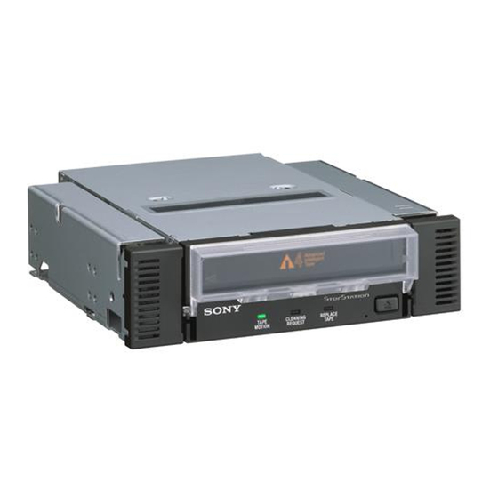
- Page 1 2-108-088-11(1) AIT Drive User’s Guide AIT-3 TAPE DRIVE SDX-700V Series 2004 Sony Corporation...
- Page 2 Klasse B.) SONY MAKES NO WARRANTY OF ANY KIND WITH REGARD TO THIS DOCUMENT. Sony shall not be liable for errors contained herein, indirect, special, incidental or consequential damages in connection with the furnishing, performance or use of this document.
-
Page 3: Important Safeguards
IMPORTANT SAFEGUARDS For your protection, please read these Power Sources – This unit should be safety instructions completely before operated only from the type of power operating the appliance, and keep this source indicated on the marking label. manual for future reference. If you are not sure of the type of electrical power, consult your dealer or Carefully observe all warnings,... - Page 4 INSTALLATION SERVICE Water and Moisture – Do not use Damage Requiring Service – Unplug power-line operated units near water - the unit from the wall outlet and refer for example, near a bathtub, servicing to qualified service washbowl, kitchen sink, or laundry personnel under the following tub, in a wet basement, or near a conditions:...
-
Page 5: Table Of Contents
Location of 3 LEDs ..................20 Drive Operation ....................21 Emergency Tape Removal Procedure ............23 WORM Function ....................25 Interface Implementation ..................27 Supported SCSI Messages ................27 Supported SCSI Commands ................27 Specifications ......................28 Product Specifications ..................28 Sony Contacts ......................30... -
Page 6: Overview
Overview The Sony SDX-700V series drives are high capacity data storage devices using Advanced Intelligent tape (AIT) technology. The SDX-700V series drives achieve high data reliability through Read-After-Write, an additional level of Error Correction Code, and other features. The Sony SDX-700V series drives store data on tape using standard... -
Page 7: Introduction
Introduction About AIT Drives SDX-700V series drives are internal AIT drive units that use data cartridges conforming to the AIT-3 format. SDX-700V series drives support AIT-1, AIT-2, and AIT-3 formats. Features The SDX-700V series drives have the following features: • Support reading and writing to data cartridges conforming to the AIT-1, AIT-2, and AIT-3 formats. -
Page 8: Precautions
Precautions Installation Avoid placing the drives in locations subject to: – high humidity – high temperature – mechanical shock and vibration – direct sunlight For details, see “Specifications” on page 28. Operation • Do not move the drives while they are operating. It may cause malfunctions. -
Page 9: Useable Cartridges
Useable Cartridges SDX-700V series can be used with data cartridges marked with the AIT-1, AIT-2 or AIT-3 logo. Note Be sure to use only data cartridges designed specifically for AIT (do not use 8 mm video cartridges) as this may damage the drives. -
Page 10: Installation
Installation SCSI Connection/Setting the SCSI ID SCSI ID SCSI ID SCSI 68pin Connector Jumpers Power Connector GND GND 12 V Parity Disable Enable Note : = CLOSED/Jumper OPEN/Jumper not installed Don’t care Parity Disable Jumper Parity check function can be disabled by Jumper. Parity check is disabled while left end jumper is installed. -
Page 11: Option Switches (Dip Switch)
Option Switches (DIP Switch) DIP Switch DIP Switch Positions Default Drive Mode (OFF) Drive Mode (OFF) Drive Mode (OFF) Drive Mode (OFF) Terminator Power (ON) Periodic Cleaning Req (ON) DC Control (1) (ON) DC Control (2) (OFF) - Page 12 DC Control (1) DC Control (2) Emulation Mode returns the following in the Product Identification field of Inquiry of a SDX-700V series drive. SDX-700C Data Compression Control DIP switch Data compression can be selected by DIP switches. Data compression is enabled while position 7 [DC Control (1)] is ON.
- Page 13 Terminator Power Control DIP switch This DIP switch determines whether terminator power is supplied to the SCSI bus. To enable terminator power, set position 5 [Terminator Power] switch to ON. Cleaning Request Mode Periodic cleaning requests can be enabled by a DIP switch. Drive Mode Drive Mode Drive Mode...
-
Page 14: Mounting Holes
Mounting Holes For 3.5" Standard Height 7.6 0.5 mm [0.3" 0.02"] 6-M3 (depth 2.5mm [0.10"] max.) 6-M3 (depth 2.5mm [0.10"] max.) 4.8 0.5mm 94.0 0.5mm [3.70" 0.02"] [0.19" 0.02"] 101.6 0.5mm [4.00" 0.02"] 41.2 0.5mm [1.62" 0.02"] For 5.25" Half Height 7.6 0.5 mm [0.3"... -
Page 15: Reconfiguring From 5.25" Model To 3.5" Model
Reconfiguring from 5.25" Model to 3.5" Model You can reconfigure the 5.25" model to the 3.5" model yourself. Remove the 2 screws for each side rail. Take the side rail off. Side Rail (L) Side Rail (R) -
Page 16: Orientation
Orientation 10 10 10 10... -
Page 17: Attaching And Removing The Dust Cover
Attaching and Removing the Dust Cover Attaching the Dust Cover Align the dust cover’s hinge clips (one on each side) with the pins of the drive bezel. • The dust cover should be positioned so that the magnets on the cover’s back face the drive bezel. - Page 18 Press down at an angle on each side in turn until you hear the hinge clips click into place. Caution Do not press the dust cover in horizontally from the front. Doing so could cause the dust cover to break. Close the dust cover.
-
Page 19: Removing The Dust Cover
Removing the Dust Cover Open the dust cover. Holding the dust cover at both corners, carefully raise the dust cover. The dust cover hinge clips and drive bezel pins uncouple. Note We recommend that you use the drive with the dust cover. -
Page 20: Operation
Operation Location of 3 LEDs There are three LED indicatiors (TAPE MOTION LED, CLEANING REQUEST LED, REPLACE TAPE LED) and an EJECT button on the front panel of the SDX-700V series drives. Front Panel Advanced Intelligent Tape TAPE CLEANING REPLACE... -
Page 21: Drive Operation
Drive Operation Loading a Cartridge Note While setting the data cartridge, do not turn off the host computer. This may cause a malfunction or damage data. Turn on the host computer. Check that the drive’s TAPE MOTION LED, CLEANING REQUEST LED and REPLACE TAPE LED go off. -
Page 22: Unloading A Cartridge
Using a Cleaning Cartridge A cleaning function is built into SDX-700V series drives so the use of a cleaning cartridge is not needed. If, however, the drive experiences excessive errors, the use of a Sony cleaning cartridge is recommended. -
Page 23: Emergency Tape Removal Procedure
Emergency Tape Removal Procedure Remove the drive from the chassis or enclosure to allow access to the bottom of the drive. Remove the drive’s top cover. Locate the small opening in the bottom of the drive and insert the tip of a precision screwdriver so that the Loading motor shaft can be rotated. - Page 24 After the tape slack has been removed, continue to turn the Loading motor shaft located on the bottom of the drive clockwise with a precision screwdriver until the tape cartridge is lifted out of the drive mechanism and is ejected. Return the drive to Sony for repair.
-
Page 25: Worm Function
WORM Function SDX-700V series drives support the WORM function. This section explains the WORM function. What is “WORM”? “WORM” is an acronym for “Write Once Read Many”, a function that allows data to be written to the same place on a tape only once, but permits that data to be read from the tape for any number of times. - Page 26 Notes • Sony cannot accept liability for data written onto a WORM cartridge that is lost as a result of using this unit. • Sony accepts no responsibility for any financial damages, lost profits, or...
-
Page 27: Interface Implementation
Interface Implementation Supported SCSI Messages Abort Message Parity Error Bus Device Reset Message Reject Command Complete No Operation Disconnect Restore Pointers Extended Message Save Data Pointer – Synchronous Data Transfer Request – Wide Data Transfer Request Identify ( w/&w/o Disconnect ) Ignore Wide Residue Supported SCSI Commands Report Luns... -
Page 28: Specifications
Specifications Product Specifications Dimensions (not including bezel and protruding parts) 3.5" 5.25" Height 41.2 mm (1.62 in) 41.2 mm (1.62 in) Width 101.6 mm (4.0 in) 146.0 mm (5.75 in) Depth 155.0 mm (6.1 in) 155.0 mm (6.1 in) Mass 3.5"... -
Page 29: Temperature And Humidity Range
Shock Operating No Data Loss Half Sine Performance 5 G Peak 3 ms 3 axes, 3 directions *Interval of 10 seconds Non-operating No Device Damage Half Sine 90 G Peak 3 ms (30 G Peak 11 ms) 3 axes, 3 directions *Interval of 10 seconds Temperature and Humidity Range Temperature... -
Page 30: Sony Contacts
TEL: (416) 499-1414 or (1) 800-961-7669 FAX: (416) 499-8541 Sony Business Europe URL: http://www.sonyisstorage.com/ Electronics Devices Marketing (Singapore) (A division company of Sony Electronics (S) Pte. Ltd.) Enterprise Storage Solutions Dept. 2 International Business Park, #01-10 Tower One, The Strategy, Singapore 609930 TEL: 65-6544-8000 FAX: 65-6544-7390 Sony Corporation of Hong Kong Ltd. - Page 31 Sony Corporation of Hong Kong Ltd. Shanghai Rep. Office 44F., HSBC Tower, 101 Yin Cheng East Road, Pudong, New Area, Shanghai, P.R.C. Postcode 200120 TEL: 86-21-6841-3222 FAX: 86-21-6841-0280 Sony Brasil Ltda. Rua Inocéncio Tobias, 125-BlocoA, CEP01144-000, São Paulo -SP-Brasil TEL: (55) 11-3824-6586 to 6598 FAX: (55) 11-3611-9064 URL: http://www.sonybrasil.com...
- Page 32 Printed in Japan...