Table of Contents
Advertisement
Quick Links
Model No. 831.14923.1
Serial No.
Write the serial number in the space
above for reference.
Serial Number
•• Assembly
•• Operation
•• Maintenance
•• Part List and Drawing
Sears, Roebuck and Co.
Hoffman Estates, IL 60179
CAUTION
Read all precautions and instruc-
tions in this manual before using
this equipment. Keep this manual
for future reference.
WEIGHT SYSTEM EXERCISER
Decal
User’'s Manual
Advertisement
Table of Contents

Related Manuals for WeiderPro 831.14923.1


Summary of Contents for WeiderPro 831.14923.1
- Page 1 Model No. 831.14923.1 Serial No. WEIGHT SYSTEM EXERCISER Write the serial number in the space User’’s Manual above for reference. Serial Number Decal •• Assembly •• Operation •• Maintenance •• Part List and Drawing Sears, Roebuck and Co. Hoffman Estates, IL 60179...
-
Page 2: Table Of Contents
TABLE OF CONTENTS WARNING DECAL PLACEMENT ............. . . 2 IMPORTANT PRECAUTIONS . -
Page 3: Important Precautions
IMPORTANT PRECAUTIONS WARNING: To reduce the risk of serious injury, read all important precautions and instructions in this manual and all warnings on your weight system before using your weight sys- tem. Sears assumes no responsibility for personal injury or property damage sustained by or through the use of this product. -
Page 4: Before You Begin
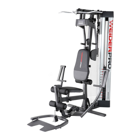
BEFORE YOU BEGIN Thank you for selecting the versatile WEIDER PRO™™ reading this manual, please see the back cover of this 8900 weight system. The weight system offers a selec- manual. To help us assist you, note the product model tion of weight stations designed to develop every major number and serial number before contacting us. -
Page 5: Part Identification Chart
PART IDENTIFICATION CHART See the drawings below to identify small parts used in assembly. The number in parentheses by each drawing is the key number of the part, from the PART LIST near the end of this manual. IMPORTANT: If you cannot find a part in the hardware kit, check to see if it has been preassembled. - Page 6 M10 x 57mm M10 x 57mm Bolt Set (80) Bolt (93) M10 x 55mm M10 x 63mm Bolt (89) Bolt (79) M10 x 50mm Button Bolt (76) M8 x 65mm Button Screw (82) M10 x 47mm Bolt (91) M10 x 65mm Bolt (75) M10 x 68mm Bolt (66) M6 x 45mm Bolt (85) M10 x 93mm Bolt (63)
-
Page 7: Assembly
ASSEMBLY •• Assembly requires two persons. •• To identify small parts, see page 5. •• Because of its weight and size, assemble the •• In addition to the included tool(s), assembly weight system in the location where it will be requires the following tool(s): used. - Page 8 2. Orient the Base (1) and the Side Stabilizers (2) as shown. Attach the Side Stabilizers (2) to the Base (1) with two M10 x 95mm Bolts (78) and two M10 Locknuts (74). Do not fully tighten the Locknuts yet. Warning Decal 3.
- Page 9 5. Orient the Upright (5) as shown. Attach the Upright (5) to the Base (1) and to the Side Stabilizers (2) with four M10 x 55mm Bolts (79), four M10 Washers (88), and four M10 Locknuts (74). Do not fully tighten the Locknuts yet.
- Page 10 6. Orient the Leg (10) as shown. Attach the Leg (10) to the Base (1) with two M10 x 55mm Bolts (79), two M10 Washers (88), and two M10 Locknuts (74). Do not fully tighten the Locknuts yet. 7. Orient the Seat Tube (8) as shown. Attach the Seat Tube (8) to the Leg (10) with two M10 x 68mm Bolts (66), two M10 Washers (88), and two M10 Locknuts (74).
- Page 11 8. Using a plastic bag to keep your fingers clean, apply some of the included grease to an M10 x Grease 57mm Bolt Set (80). Orient the Leg Lever (13) so that the high end of the bracket is in the location shown. Attach the Leg Lever (13) to the Leg (10) with the M10 x 57mm Bolt Set (80).
- Page 12 11. Orient the Weight Guides (31) so that the indi- cated holes are closer to the floor. Insert the Weight Guides (31) into the Base (1). Attach each Weight Guide with an M10 x 63mm Bolt (89) and an M10 Locknut (74). Holes...
- Page 13 12. Orient the Bottom Cover (28) so that the notch is in the indicated location. Slide the Bottom Cover (28) downward over the Weight Guides (31) and the Burn Cable (45) as shown. Make sure that the Burn Cable is in the indicated notch in the Bottom Cover.
- Page 14 14. Slide a Bumper (40) onto each Weight Guide (31). Orient a Weight (30) so that the pin hole is in the indicated location. Slide the Weight onto the Weight Guides (31). Then, route the end of the Burn Cable (45) upward through the center of the Weight.
- Page 15 17. Attach the Top Frame (6) to the Weight Guides (31) with two M10 x 43mm Bolts (65), two M10 Curved Washers (86), and two M10 Locknuts (74). See step 16. Tighten the M10 Locknuts (74). 18. Note: For clarity, the Top Cover (27) is not shown in this step.
- Page 16 19. Apply grease to an M10 x 130mm Bolt (11). Identify the Left and Right Press Arms (17, 18) and orient them as shown. Insert the Press Arm Spacer (42) between the Press Arms (17, 18) as shown. Attach the Press Arms (17, 18) to the Base (1) with the M10 x 130mm Bolt (11) and an M10 Locknut (74).
- Page 17 21. Attach the Butterfly Frame (7) to the Top Frame (6) with two M10 x 93mm Bolts (63), two M10 Washers (88), and two M10 Locknuts (74). Do not fully tighten the Locknuts yet. Insert a Ball Detent Assembly (96) into each Butterfly Arm (15, 16).
- Page 18 23. See the CABLE DIAGRAM. Identify the Low Cable (43). Route either end of the Low Cable (43) through the Leg Lever (13) and through the Leg (10). Attach a Pulley (69) inside the Leg Lever (13) above the Low Cable (43) with an M10 x 63mm Bolt (89), two 12.7mm Spacers (73), and an M10 Locknut (74).
- Page 19 26. Route the Low Cable (43) over a Pulley (69). Attach the Pulley (69) and a Cable Trap (71) between the Press Arms (17, 18) with an M10 x 125mm Bolt (83) and an M10 Washer (88). Make sure that the Cable Trap is oriented to hold the Low Cable in the groove of the Pulley.
- Page 20 29. See the CABLE DIAGRAM. Identify the High Cable (44). Route the High Cable (44) upward through the Top Frame (6) and over a Pulley (69). Make sure that the eyelet end of the High Cable is in the location shown. Attach the Pulley (69) inside the Top Frame (6) with an M10 x 68mm Bolt (66), two 14.8mm Spacers (95), and an M10 Locknut (74).
- Page 21 32. Route the High Cable (44) around a Pulley (69). Attach the Pulley (69) and a Cable Trap (71) to the Right Butterfly Pulley Bracket (21) with an M10 x 47mm Bolt (91) and an M10 Locknut (74). Make sure that the Cable Trap is oriented to hold the High Cable in the groove of the Pulley.
- Page 22 35. Route the High Cable (44) under a V-pulley (67). Attach the V-pulley (67) and a Cable Trap (71) to the Upright (5) with an M10 x 57mm Bolt (93) and an M10 Locknut (74). Make sure that the Slot Cable Trap is oriented to hold the High Cable in the groove of the V-pulley.
- Page 23 37. Hold a Pulley (69) under the High Cable (44) in the location shown. Attach the Pulley (69) and a Cable Trap (71) to the Top Frame (6) with an M10 x 93mm Bolt (63), an M10 Washer (88), and an M10 Locknut (74).
-
Page 24: Button
40. Route the Low Cable (43) under a Pulley (69). Attach the Pulley (69), a Cable Trap (71), and two Half Guards (72) to the indicated bracket on the Base (1) with an M10 x 50mm Button Bolt (76) and an M10 Locknut (74). Make sure that the Cable Trap (71) is oriented to hold the Low Cable (43) in the groove of the Pulley (69). - Page 25 43. Route the Low Cable (43) under a Pulley (69). Attach the Pulley (69), a Cable Trap (71), and two Half Guards (72) to the indicated bracket on the Base (1) with an M10 x 50mm Button Bolt (76) and an M10 Locknut (74). Make sure that the Cable Trap (71) is oriented to hold the Low Cable (43) in the groove of the Pulley (69).
- Page 26 45. Orient the Weight Selector (32) as shown. Tighten the lower end of the Burn Cable (45) completely into the lower end of the Weight Selector (32). Next, insert the end of the High Cable (44) through the upper end of the Burn Cable (45), and tighten the High Cable at least five com- plete turns into the Weight Selector (32).
- Page 27 47. Insert the Weight Pin (41) under a Weight (30). 48. Insert the Lock Pin (39) through a Weight Guide (31), and secure the Lock (38) into the Lock Pin. 49. Orient the Seat (24) and a Cushion Frame (9) as shown.
- Page 28 50. Insert the Cushion Frame (9) into the Seat Tube (8). Tighten an Adjustment Knob (29) into the Seat Tube (8) and into one of the holes in the Cushion Frame (9). Make sure that the Adjustment Knob is engaged in a hole. 51.
- Page 29 53. Orient the Backrest (25) and a Cushion Frame (9) as shown. Attach the Backrest (25) to the Cushion Frame (9) with four M6 x 16mm Screws (62). 54. Insert the Cushion Frame (9) into the Upright (5). Tighten an Adjustment Knob (29) into the Upright (5) and into one of the holes in the Cushion Frame (9).
- Page 30 55. Identify the Left and Right and Butterfly Pads (22, 23). Attach the Right Butterfly Pad (23) to the Right Butterfly Arm (16) with two M6 x 16mm Screws (62). Attach the Left Butterfly Pad (22) to the Left Butterfly Arm (15) in the same way. 56.
- Page 31 57. Note: For clarity, the Top Cover (27) is not shown in steps 57 to 59. Identify the Center Shroud (33), and orient it as shown. Insert the Center Shroud (33) into the Bottom Cover (28). 58. Attach the top of the Center Shroud (33) to the Top Frame (6) with two ST4.2 x 19mm Screws (90).
- Page 32 59. Insert the Left Shroud (110) into the Bottom Cover (28). Attach the top of the Left Shroud (110) to the Top Frame (6) with an ST4.2 x 19mm Screw (90). Repeat this step to attach the Right Shroud (34).
- Page 33 60. Press the Top Cover (27) onto the Top Frame (6) as shown. Orient the Burn Band (26) and the Burn Bracket (14) as shown. Insert the Burn Band into the Burn Bracket. Attach the Burn Band (26) and the Burn Bracket (14) to the Top Frame (6) with two M6 x 45mm Bolts (85) and two M6 Locknuts (87).
- Page 34 62. Insert a Pulley (69) under the High Cable (44) in the location shown. Attach the Pulley (69) inside the Top Frame (6) with an M10 x 65mm Bolt (75), two M10 Washers (88), two 12.7mm Spacers (73), and an M10 Locknut (74).
-
Page 35: Adjustment
ADJUSTMENT This section explains how to adjust the weight system. See the EXERCISE GUIDELINES on page 42 for impor- tant information about how to get the most benefit from your exercise program. Also, refer to the accompanying exercise guide to see the correct form for several exercises. Make sure that all parts are properly tightened each time the weight system is used. - Page 36 ATTACHING THE ACCESSORIES Attach the Lat Bar (47) to the High Cable (44) at the high pulley station with a Cable Clip (50). For some exercises, attach the Chain (not shown) between the Lat Bar (47) and the High Cable (44) with two Cable Clips (50).
- Page 37 CONVERTING THE FOOT PLATE To use the Foot Plate (4) as a footrest while using the low pulley station, rotate the Foot Plate upward. When you are not using the Foot Plate (4) as a foot- rest, rotate the Foot Plate downward so that it is flat on the floor.
-
Page 38: Weight Resistance Chart
WEIGHT RESISTANCE CHART The chart below shows the approximate weight resistance at each exercise station. The numbers in the left col- umn refer to the 12.5-lb. weights. Note: The weight resistance shown for the butterfly arm station is for each arm. -
Page 39: Cable Diagram
CABLE DIAGRAM The diagram below shows the proper routing of the cables. The numbers in each drawing show the proper route of that cable. Cut along the dotted line, and refer to this diagram while you assemble the cables and the pulleys. If the cables and the pulleys are not assembled correctly, the weight system will not function properly and damage may occur. - Page 40 NOTES...
-
Page 41: Maintenance
MAINTENANCE Make sure that all parts are properly tightened each time the weight system is used. Replace any worn parts immediately. To clean the weight system, use a damp cloth and a mild, non-abrasive detergent; do not use solvents to clean the weight system. TIGHTENING THE CABLES Woven cable, the type of cable used on the weight system, can stretch slightly when it is first used. -
Page 42: Exercise Guidelines
EXERCISE GUIDELINES FOUR TYPES OF STRENGTH WORKOUTS workout, and the numbers of repetitions and sets to complete. Progress at your own pace and be sensitive Note: A ““repetition”” is one complete cycle of an to your body’’s signals. Follow each workout with at exercise, such as one sit-up. -
Page 43: Part List
PART LIST Model No. 831.14923.1 R0513A Key No. Qty. Description Key No. Qty. Description Base Double Strap Side Stabilizer Lat Bar U-stabilizer Chain Foot Plate Ankle Strap Upright Cable Clip Top Frame Composite Bushing Butter y Frame Upper Butter y Bushing... - Page 44 Key No. Qty. Description Key No. Qty. Description M10 x 47mm Bolt Lat Bar Foam Grip Leg Lever Bumper Lat Bar Cap M10 x 57mm Bolt Plastic Bushing 6.35mm Spacer Handle 14.8mm Spacer M4 x 12mm Bolt Ball Detent Assembly M4 Locknut M10 x 40mm Bolt Containment Bracket...
-
Page 45: Exploded Drawing
EXPLODED DRAWING A Model No. 831.14923.1 R0513A... - Page 46 EXPLODED DRAWING B Model No. 831.14923.1 R0513A...
- Page 47 EXPLODED DRAWING C Model No. 831.14923.1 R0513A...
-
Page 48: 90 Day Full Warranty
90 DAY FULL WARRANTY If this Sears Weight System Exerciser fails due to a defect in material or workmanship within 90 days of the date of purchase, call 1-800-4-MY-HOME ® (1-800-469-4663) to arrange for free repair (or replace- ment if repair proves impossible). This warranty does not apply when the Weight System Exerciser is used commercially or for rental pur- poses.