Table of Contents
Advertisement
Advertisement
Chapters
Table of Contents

Related Manuals for Asus A78M-A


Summary of Contents for Asus A78M-A
- Page 1 A78M-A...
- Page 2 Product warranty or service will not be extended if: (1) the product is repaired, modified or altered, unless such repair, modification of alteration is authorized in writing by ASUS; or (2) the serial number of the product is defaced or missing.
-
Page 3: Table Of Contents
Contents Safety information ..................iv About this guide ..................iv Package contents ..................vi A78M-A specifications summary .............. vi Product introduction Before you proceed ..............1-1 Motherboard overview ..............1-2 Accelerated Processing Unit (APU) ........... 1-4 System memory ................1-8 Expansion slots ................ -
Page 4: Safety Information
Safety information Electrical safety • To prevent electrical shock hazard, disconnect the power cable from the electrical outlet before relocating the system. • When adding or removing devices to or from the system, ensure that the power cables for the devices are unplugged before the signal cables are connected. If possible, disconnect all power cables from the existing system before you add a device. -
Page 5: Conventions Used In This Guide
Refer to the following sources for additional information and for product and software updates. ASUS websites The ASUS website provides updated information on ASUS hardware and software products. Refer to the ASUS contact information. Optional documentation Your product package may include optional documentation, such as warranty flyers, that may have been added by your dealer. -
Page 6: Package Contents
APUs. • The maximum 64GB memory capacity can be supported with 16GB or above DIMMs. ASUS will update the memory QVL once the DIMMs are available in the market. • Refer to www.asus.com for the latest Memory QVL (Qualified Vendors List). - Page 7 - ASUS AI Charger - ASUS Disk Unlocker - ASUS AI Suite 3 - ASUS Anti Surge - ASUS UEFI BIOS EZ Mode featuring friendly graphics user interface ASUS Quiet Thermal Solution - ASUS Fan Xpert - Stylish Fanless Design Heat-sink solution...
- Page 8 BIOS features 64 Mb Flash ROM, UEFI AMI BIOS, PnP, DMI 2.0, WfM 2.0, SM BIOS 2.7, ACPI 2.0a, Multi-language BIOS, ASUS EZ Flash 2, ASUS CrashFreen BIOS 3, F12 Printscreen function, F3 Shortcut function and ASUS DRAM SPD (Serial Presence Detect) memory information...
-
Page 9: Product Introduction
ON, in sleep mode, or in soft-off mode. This is a reminder that you should shut down the system and unplug the power cable before removing or plugging in any motherboard component. The illustration below shows the location of the onboard LED. SB_PWR A78M-A Standby Power Powered Off A78M-A Onboard LED ASUS A78M-A... -
Page 10: Motherboard Overview
Place six screws into the holes indicated by circles to secure the motherboard to the chassis. Do not overtighten the screws! Doing so can damage the motherboard. Place this side towards the rear of the chassis A78M-A Chapter 1: Product introduction... -
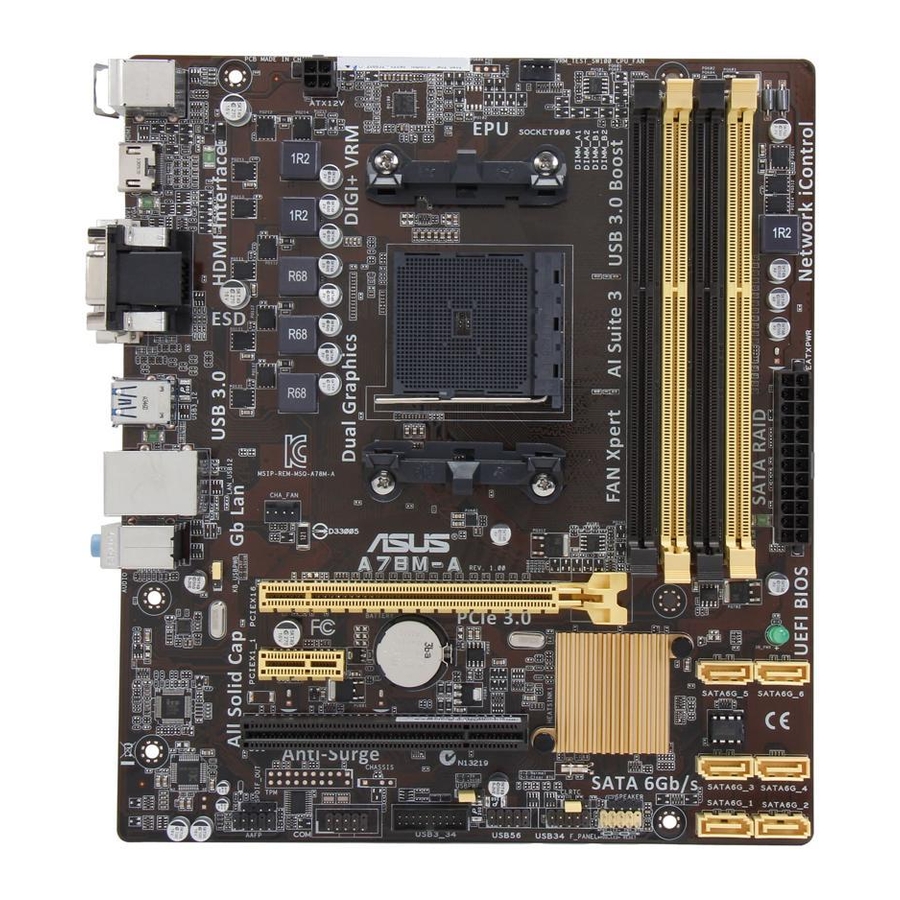
Page 11: Motherboard Layout
Motherboard layout 20.8cm(8.2in) CPU_FAN KBMS DIGI ATX12V +VRM HDMI USB3_12 LAN_USB12 CHA_FAN AUDIO A78M-A PCIEX16 SB_PWR 8111GR BATTERY PCIEX1_1 ® SATA6G_5 SATA6G_6 Super 64Mb PCI1 BIOS SATA6G_3 SATA6G_4 SPEAKER SPDIF_OUT USB3_34 SATA6G_1 SATA6G_2 AAFP USB56 USB34 F_PANEL 12 11 ASUS A78M-A... -
Page 12: Accelerated Processing Unit (Apu)
Ensure that you use an APU designed for the FM2+ socket. The APU fits in only one correct orientation. DO NOT force the APU into the socket to prevent bending the pins and damaging the APU! A78M-A A78M-A CPU socket FM2+ Chapter 1: Product introduction... - Page 13 1.3.1 APU installation ASUS A78M-A...
-
Page 14: Apu Heatsink And Fan Assembly Installation
1.3.2 APU heatsink and fan assembly installation Apply the Thermal Interface Material to the APU heatsink and APU before you install the heatsink and fan if necessary. To install the APU heatsink and fan assembly Chapter 1: Product introduction... - Page 15 To uninstall the APU heatsink and fan assembly ASUS A78M-A...
-
Page 16: System Memory
Sockets Channel A DIMM_A1 and DIMM_A2 Channel B DIMM_B1 and DIMM_B2 A78M-A A78M-A 240-pin DDR3 DIMM sockets 1.4.2 Memory configurations You may install 1GB, 2GB, 4GB, and 8GB unbuffered non-ECC DDR3 DIMMs into the DIMM sockets. • You may install varying memory sizes in Channel A and Channel B. The system maps the total size of the lower-sized channel for the dual-channel configuration. -
Page 17: Installing A Dimm
• For system stability, use a more efficient memory cooling system to support a full memory load (4 DIMMs) or overclocking condition. • Visit the ASUS website at: www.asus.com for the latest QVL. 1.4.3 Installing a DIMM ASUS A78M-A... -
Page 18: Expansion Slots
To remove a DIMM Expansion slots In the future, you may need to install expansion cards. The following sub-sections describe the slots and the expansion cards that they support. Unplug the power cord before adding or removing expansion cards. Failure to do so may cause you physical injury and damage motherboard components. -
Page 19: Usb3
– – – OnChip XHCI controller2 – shared – – – – – – OnChip USB EHCI 1/2/3 – shared – – – – – – OnChip USB OHCI – – shared – – – – – ASUS A78M-A 1-11... -
Page 20: Jumpers
A78M-A Normal Clear RTC (Default) A78M-A Clear RTC RAM To erase the RTC RAM: Turn OFF the computer and unplug the power cord. Move the jumper cap from pins 1-2 (default) to pins 2-3. Keep the cap on pins 2-3 for about 5-10 seconds, then move the cap back to pins 1-2. -
Page 21: Usb Device Wake-Up (3-Pin Usbpwf)
A78M-A +5VSB (Default) A78M-A Keyboard and USB device wake up USB device wake-up (3-pin USBPWF) Set this jumper to +5V to wake up the computer from S1 sleep mode (CPU stopped, DRAM refreshed, system running in low power mode) using the connected USB devices. -
Page 22: Connectors
Connectors 1.7.1 Rear panel connectors PS/2 mouse port. This port is for a PS/2 mouse. HDMI port. This port is for a High-Definition Multimedia Interface (HDMI) connector, and is HDCP compliant allowing playback of HD DVD, Blu-ray, and other protected content. - Page 23 USB 3.0 devices. DVI-D port. This port is for any DVI-D compatible device. DVI-D can’t be converted to output RGB Signal to CRT and isn’t compatible with DVI-I. PS/2 keyboard port. This port is for a PS/2 keyboard. ASUS A78M-A 1-15...
-
Page 24: Cpu And Chassis Fan Connectors (4-Pin Cpu_Fan, And 4-Pin Cha_Fan)
These are not jumpers! DO NOT place jumper caps on the fan connectors. • The CPU_FAN connector supports a CPU fan of maximum 2A (24W) fan power. • The 4-pin CPU_FAN and chassis fan support the ASUS Fan Xpert feature. Chapter 1: Product introduction 1-16... -
Page 25: Atx Power Connectors (24-Pin Eatxpwr, 4-Pin Atx12V)
The system may become unstable or may not boot up if the power is inadequate. • If you are uncertain about the minimum power supply requirement for your system, refer to the Recommended Power Supply Wattage Calculator at http://support.asus. com/PowerSupplyCalculator/PSCalculator.aspx?SLanguage=en-us for details. ASUS A78M-A 1-17... - Page 26 SATA6G_1 SATA6G_2 A78M-A A78M-A SATA 6.0Gb/s connectors • These connectors are set to AHCI mode by default. If you intend to create a Serial ATA RAID set using these connectors, set the type of the SATA connectors in the BIOS to [RAID].
-
Page 27: Speaker Connector (4-Pin Speaker)
PIN 1 A78M-A +HDD_LED RESET A78M-A System panel connector • System power LED (2-pin PWR_LED) This 2-pin connector is for the system power LED. Connect the chassis power LED cable to this connector. The system power LED lights up when you turn on the system power, and blinks when the system is in sleep mode. -
Page 28: Digital Audio Connector (4-1 Pin Spdif_Out)
A78M-A HD-audio-compliant Legacy AC’97 pin definition compliant definition A78M-A Front panel audio connector • We recommend that you connect a high-definition front panel audio module to this connector to avail of the motherboard high-definition audio capability. • If you want to connect a high definition front panel audio module to this connector, set the Front Panel Type item in the BIOS to [HD]. -
Page 29: Usb 2.0 Connectors (10-1 Pin Usb34, Usb56)
USB-chargeable devices, optimized power efficiency and backward compatibility with USB 2.0. USB3_34 PIN 1 A78M-A A78M-A USB3.0 Front panel connector You can connect the ASUS front panel USB 3.0 bracket to this connector to obtain the front panel USB 3.0 solution. ASUS A78M-A 1-21... -
Page 30: Serial Port Connector (10-1 Pin Com)
This connector is for a serial (COM) port. Connect the serial port module cable to this connector, then install the module to a slot opening at the back of the system chassis. PIN 1 A78M-A A78M-A Serial port connectors The COM module is purchased separately. Chapter 1: Product introduction 1-22... -
Page 31: Software Support
The contents of the Support DVD are subject to change at any time without notice. Visit the ASUS website at www.asus.com for updates. To run the Support DVD Place the Support DVD into the optical drive. - Page 32 Chapter 1: Product introduction 1-24...
-
Page 33: Bios Information
Managing and updating your BIOS Save a copy of the original motherboard BIOS file to a USB flash disk in case you need to restore the BIOS in the future. Copy the original motherboard BIOS using the ASUS Update utility. -
Page 34: Asus Ez Flash
2.1.2 ASUS EZ Flash 2 The ASUS EZ Flash 2 feature allows you to update the BIOS without using an OS-based utility. Before you start using this utility, download the latest BIOS file from the ASUS website at www.asus.com. To update the BIOS using EZ Flash 2: Insert the USB flash disk that contains the latest BIOS file to the USB port. -
Page 35: Asus Crashfree Bios 3 Utility
2.1.3 ASUS CrashFree BIOS 3 utility The ASUS CrashFree BIOS 3 is an auto recovery tool that allows you to restore the BIOS file when it fails or gets corrupted during the updating process. You can restore a corrupted BIOS file using the motherboard support DVD or a USB flash drive that contains the updated BIOS file. - Page 36 Insert the USB flash drive with the latest BIOS file and BIOS Updater to the USB port. Boot your computer. When the ASUS Logo appears, press <F8> to show the BIOS Boot Device Select Menu. Insert the support DVD into the optical drive and select the optical drive as the boot device.
- Page 37 Ensure to load the BIOS default settings to ensure system compatibility and stability. Select the Load Optimized Defaults item under the Exit menu. Refer to section 2.10 Exit menu for details. • Ensure to connect all SATA hard disk drives after updating the BIOS file if you have disconnected them. ASUS A78M-A...
-
Page 38: Bios Setup Program
BIOS setup program Use the BIOS Setup program to update the BIOS or configure its parameters. The BIOS screens include navigation keys and brief online help to guide you in using the BIOS Setup program. Entering BIOS Setup at startup To enter BIOS Setup at startup: •... -
Page 39: Advanced Mode
The Advanced Mode provides advanced options for experienced end-users to configure the BIOS settings. The figure below shows an example of the Advanced Mode. Refer to the following sections for the detailed configurations. To access the EZ Mode, click Exit, then select ASUS EZ Mode or press F7. ASUS A78M-A... -
Page 40: Menu Bar
Back button Menu items Menu bar Configuration fields General help Last modified Navigation keys Pop-up window settings Quick Scroll bar note Menu bar The menu bar on top of the screen has the following main items: My Favorites For saving the frequently-used system settings and configuration Main For changing the basic system configuration Ai Tweaker... -
Page 41: My Favorites
This button allows you to enter notes of the activities that you have done in BIOS. Last Modified button This button shows the items that you last modified and saved in BIOS Setup. My Favorites MyFavorites is your personal space where you can easily save and access your favorite BIOS items. ASUS A78M-A... -
Page 42: Main Menu
Adding items to My Favorites To add frequently-used BIOS items to My Favorites: Use the arrow keys to select an item that you want to add. When using a mouse, hover the pointer to the item. Press <F4> on your keyboard or right-click on your mouse to add the item to My Favorites page. -
Page 43: Administrator Password
To clear the user password, follow the same steps as in changing a user password, but press <Enter> when prompted to create/confirm the password. After you clear the password, the User Password item on top of the screen shows Not Installed. ASUS A78M-A 2-11... -
Page 44: Ai Tweaker Menu
Ai Tweaker menu The Ai Tweaker menu items allow you to configure overclocking-related items. Be cautious when changing the settings of the Ai Tweaker menu items. Incorrect field values can cause the system to malfunction. The configuration options for this section vary depending on the CPU and DIMM model you installed on the motherboard. - Page 45 This item appears only when The EPU Power Saving Mode is set to [Enabled] and allows you to set power saving mode. Configuration options: [Auto] [Light Power Saving Mode] [Medium Power Saving Mode] [Max Power Saving Mode] ASUS A78M-A 2-13...
-
Page 46: Dram Timing Control
2.5.6 DRAM Timing Control The sub-items in this menu allow you to set the DRAM timing control features. Use the <+> and <-> keys to adjust the value. To restore the default setting, type [auto] using the keyboard and press <Enter>. Changing the values in this menu may cause the system to become unstable! If this happens, revert to the default settings. - Page 47 Reducing phase number under light system loading to increase VRM efficiency. [Standard] Proceeds phase control depending on the CPU loading. [Optimized] Loads the ASUS optimized phase tuning profile. [Extreme] Proceeds the full phase mode. [Manual Adjustment] Allows manual adjustment.
-
Page 48: Advanced Menu
CPU Power Duty Control [T.Probe] [T.Probe] Maintains the VRM thermal balance. [Extreme] Maintains the VRM current balance. Do not remove the thermal module while changing the DIGI+VRM related parameters. The thermal conditions should be monitored. Advanced menu The Advanced menu items allow you to change the settings for the CPU and other system devices. -
Page 49: Sata Configuration
Set to [AHCI] when you want the SATA hard disk drives to use the AHCI (Advanced Host Controller Interface). The AHCI allows the onboard storage driver to enable advanced Serial ATA features that increases storage performance on random workloads by allowing the drive to internally optimize the order of commands. ASUS A78M-A 2-17... - Page 50 SATA Port 5 - Port 6 [AHCI] This item only appears when OnChip SATA Type is set to [AHCI]. If SATA ports 5, 6 are configured as [AHCI], the ports can only be used under Windows OS with the ® requested drivers installed.
-
Page 51: Usb Configuration
Sets the front panel audio connector (AAFP) mode to high definition audio. [AC97] Sets the front panel audio connector (AAFP) mode to legacy AC’97. SPDIF Out Type [SPDIF] [SPDIF] Sets to [SPDIF] for SPDIF audio output. [HDMI] Sets to [HDMI] for HDMI audio output. ASUS A78M-A 2-19... -
Page 52: Serial Port Configuration
Realtek LAN Controller [Enabled] [Enabled] Enables the Realtek LAN controller. [Disabled] Disables the controller. Realtek PXE OPROM [Disabled] This item appears only when you set the Realtek LAN Controller item to [Enabled] and allows you to enable or disable the Rom of the Realtek LAN controller. Configuration options: [Enabled] [Disabled] Serial Port Configuration The sub-items in this menu allow you to set the serial port configuration. -
Page 53: Network Stack
This item allows user to disable or enable the Ipv4 PXE Boot support. Configuration options: [Disabled] [Enable] Ipv6 PXE Support [Enabled] This item allows user to disable or enable the Ipv6 PXE Boot support. Configuration options: [Disabled] [Enabled] ASUS A78M-A 2-21... -
Page 54: Monitor Menu
Monitor menu The Monitor menu displays the system temperature/power status, and allows you to change the fan settings. Scroll down to display the following items: 2-22 Chapter 2: BIOS information... - Page 55 Use the <+> and <-> keys to adjust the minimum CPU fan duty cycle. The values range from 0% to 100%. When the CPU temperature is under the lower limit, the CPU fan will operate at the minimum duty cycle. ASUS A78M-A 2-23...
- Page 56 2.7.4 Chassis Q-Fan Control [Enabled] [Disabled] Disables the Chassis1 Q-Fan control feature. [Enabled] Enables the Chassis1 Q-Fan control feature. Fan Speed Low Limit [600 RPM] This item appears only when you enable the Chassis1 Q-Fan Control feature and allows you to disable or set the chassis1 fan warning speed. Configuration options: [Ignore] [200RPM] [300 RPM] [400 RPM] [500 RPM] [600 RPM] Q-Fan Profile [Standard] This item appears only when you enable the Chassis1 Q-Fan Control feature and...
-
Page 57: Boot Menu
Boot menu The Boot menu items allow you to change the system boot options. Scroll down to display the following items: ASUS A78M-A 2-25... - Page 58 2.8.1 Fast Boot [Enabled] [Enabled] Select to accelerate the boot speed. [Disabled] Select to go back to normal boot. The following four items appear when you set Fast Boot to [Enabled]. SATA Support [All Devices] [All Devices] All devices connected to SATA ports will be available during POST.
- Page 59 Disables this function. 2.8.7 Setup Mode [EZ Mode] [Advanced Mode] Sets Advanced Mode as the default screen for entering the BIOS setup program. [EZ Mode] Sets EZ Mode as the default screen for entering the BIOS setup program. ASUS A78M-A 2-27...
- Page 60 2.8.8 CSM (Compatibility Support Module) Allows you to configure the CSM (Compatibility Support Module) items to fully support the various VGA, bootable devices and add-on devices for better compatibility. Launch CSM [Enabled] [Auto] The system automatically detects the bootable devices and the add-on devices.
-
Page 61: Secure Boot
Secure Boot keys will not be active. Configuration options: [Yes] [No] Load PK from File Allows you to load the downloaded PK from a USB storage device. The PK file must be formatted as a UEFI variable structure with time-based authenticated variable. ASUS A78M-A 2-29... - Page 62 KEK Management The KEK (Key-exchange Key or Key Enrollment Key) manages the Signature database (db) and Revoked Signature database (dbx). Key-exchange Key (KEK) refers to Microsoft Secure Boot Key-Enrollment Key (KEK). ® Delete the KEK Allows you to delete the KEK from your system. Configuration options: [Yes] [No] Load KEK from File Allows you to load the downloaded KEK from a USB storage device.
-
Page 63: Boot Option Priorities
• To select the boot device during system startup, press <F8> when ASUS Logo appears. • To access Windows OS in Safe Mode, press <F8> after POST. -
Page 64: Tools Menu
<Enter> to display the submenu. 2.9.1 ASUS EZ Flash 2 Utility Allows you to run ASUS EZ Flash 2. Press [Enter] to launch the ASUS EZ Flash 2 screen. For more details, see section 2.1.2 ASUS EZ Flash 2. 2.9.2... -
Page 65: Exit Menu
This option allows you to exit the Setup program without saving your changes. When you select this option or if you press <Esc>, a confirmation window appears. Select Yes to discard changes and exit. ASUS EZ Mode This option allows you to enter the EZ Mode screen. Launch EFI Shell from filesystem device This option allows you to attempt to launch the UEFI Shell application (shellx64.efi) from one... - Page 66 2-34 Chapter 2: BIOS information...
-
Page 67: Appendices
Cet appareil est conforme aux normes CNR exemptes de licence d’Industrie Canada. Le fonctionnement est soumis aux deux conditions suivantes : (1) cet appareil ne doit pas provoquer d’interférences et (2) cet appareil doit accepter toute interférence, y compris celles susceptibles de provoquer un fonctionnement non souhaité de l’appareil. ASUS A78M-A... -
Page 68: Canadian Department Of Communications Statement
ASUS Recycling/Takeback Services ASUS recycling and takeback programs come from our commitment to the highest standards for protecting our environment. We believe in providing solutions for you to be able to responsibly recycle our products, batteries, other components as well as the packaging materials. -
Page 69: Asus Contact Information
+1-510-739-3777 +1-510-608-4555 Web site http://usa.asus.com Technical Support Telephone +1-812-284-0883 Support fax +1-812-282-2787 Online support http://support.asus.com/techserv/techserv.aspx ASUS COMPUTER GmbH (Germany and Austria) Address Harkort Str. 21-23, 40880 Ratingen, Germany +49-2102-959931 Web site http://www.asus.com/de Online contact http://eu-rma.asus.com/sales Technical Support Telephone +49-2102-5789555 Support Fax... - Page 70 Appendices...