Advertisement
SMART-STAT-II Remote Control Kits
INTRODUCTION
The remote control system can be operated thermo-
statically or manually from the transmitter. The system
operates on radio frequencies (RF) within a 20 foot range.
Can be used with DSI, IPI or Standing Pilot systems.
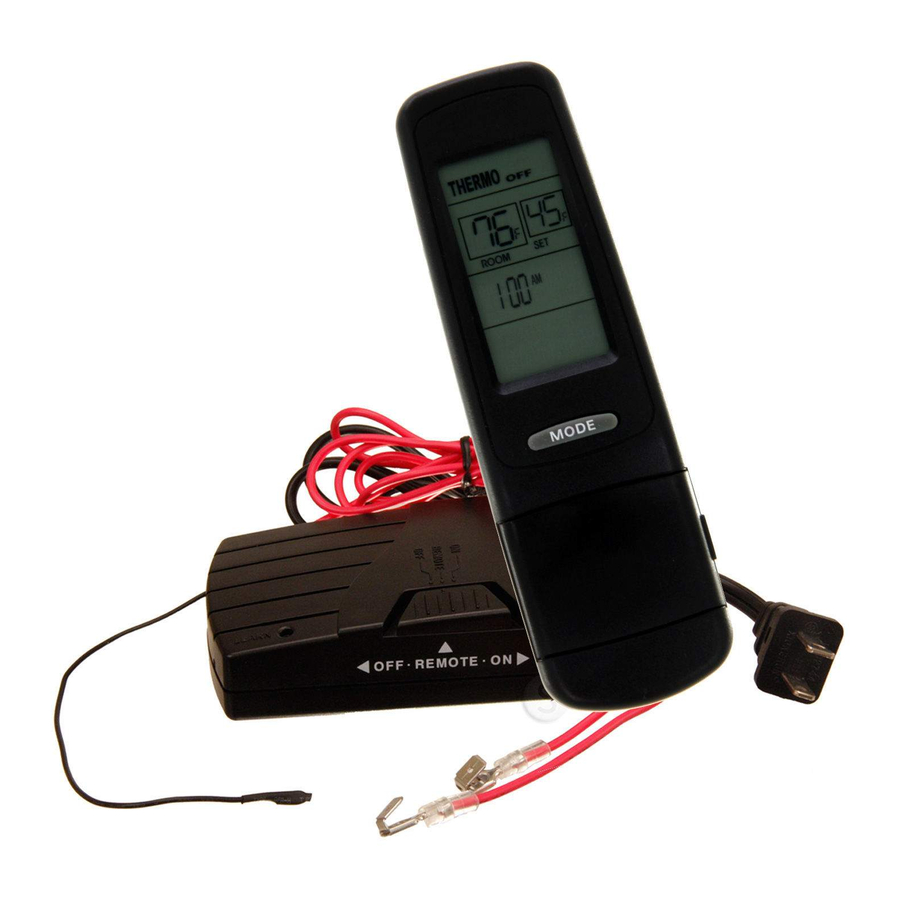
This remote control kit has a hand held transmitter that
can be used as a remote on/off or as a thermostat. The
transmitter display shows the current room tempera-
ture, target temperature, timer setting, on/off status,
low battery indicator, current time and burner/valve op-
eration. Electrical ratings for the receiver are: 110 VAC,
60 Hz.
If pertinent, see additional fireplace wiring diagrams on
pages 8 to 10.
INSTALLATION PRECAUTIONS
This remote control kit is tested and safe when installed
in accordance with this installation manual. Installa-
tion of this kit MUST be done by a qualified service
technician. It is the responsibility of the installer to read
all instructions before starting installation and to follow
these instructions carefully during installation. Modifi-
cation of the remote control system or any of its com-
ponents will void the warranty and may cause a fire
hazard.
NOTE: The factory installed junction box in the
gas fireplace must be wired with 110 VAC before
installing this kit. See Installation Instructions sec-
tion.
CAUTION: All wiring should be done by a qualified
electrician and shall be in compliance with local codes
and with the National Electric Code ANSI/NFPA No.
70-current (in the United States), or with the current
CSA C22.1 Canadian Electric Code (in Canada).
WARNING: DO NOT CONNECT 110-120 VAC
WIRING TO THE GAS CONTROL VALVE OF
THIS APPLIANCE.
Hearth & Home Technologies Inc.
20802 Kensington Boulevard, Lakeville, MN 55044
- Installation and Operating Instructions -
1
FCC REQUIREMENTS
WARNING: CHANGES OR MODIFICATIONS TO
THIS UNIT NOT EXPRESSLY APPROVED BY
THE PARTY RESPONSIBLE FOR COMPLIANCE
COULD VOID THE USER'S AUTHORITY TO
OPERATE THE EQUIPMENT.
NOTE: This equipment has been tested and found to
comply with the limits for a Class B digital device, pur-
suant to Part 15 of the FCC Rules. These limits are
designed to provide reasonable protection against harm-
ful interference in a residential installation. This equip-
ment generates, uses, and can radiate radio frequency
energy and, if not installed and used in accordance
with the instructions, may cause harmful interference
to radio communications. However, there is no guaran-
tee that interference will not occur in a particular instal-
lation.
Canadian Equipment Requirements
This digital apparatus does not exceed the (Class A/
Class B)* limits for radio noise emissions from digital
apparatus set out in the Radio Interference Regulations
of the Canadian Department of Communications. Le
present appareil numerique n'emet pas de bruits
radioelectriques depassant les limites applicables aux
appareils numeriques (de la class A/de la class B)*
prescrites dans le Reglement sur le brouillage
radioelectrique edicte par le ministere des Communi-
cations du Canada.
This device complies with RSS-210 of Industry and Sci-
ence Canada. Operation is subject to the following two
conditions: (1) this device may not cause interference,
and (2) this device must accept any interference, in-
cluding interference that may cause undesired opera-
tion of the device.
100-906F 12/06
Advertisement
Table of Contents

Related Manuals for Hearth and Home Technologies SMART-STAT-II


Summary of Contents for Hearth and Home Technologies SMART-STAT-II
- Page 1 SMART-STAT-II Remote Control Kits INTRODUCTION The remote control system can be operated thermo- statically or manually from the transmitter. The system operates on radio frequencies (RF) within a 20 foot range. Can be used with DSI, IPI or Standing Pilot systems.
-
Page 2: Installation Instructions
INSTALLATION INSTRUCTIONS Installing Electrical Service to the Junction Box WARNING: TURN ELECTRICAL POWER OFF AT THE CIRCUIT BREAKER BEFORE BEGIN- NING THIS INSTALLATION. NOTE: Some appliances do not have a cover plate. Instead, there is a hole through which the Romex clamp is attached to the outer wrap. - Page 3 Wiring Electronic Spark Ignitions The remote control receiver can be wired, in series, to a 24VAC transformer, which controls an electronic igni- tion module (see Figure 3). 1. Connect the neutral wire from the 24VAC transformer to the TR (transformer) terminal on the Electronic Module.
- Page 4 1. LOW - Battery power low. Replace batteries within two weeks. 2. TIMER - Indicates time remaining before system shuts off, when timer-programmed, 9 - hour maximum setting. 3. MODE - Indicates operation MODE of system. ON indicates the system is on, either manually or thermostatically.
- Page 5 Figure 6. Setting Button/Child Proof Lockout Setting C Scale The factory setting for temperature is degrees Fahrenheit F). To change this setting to degrees Centigrade ( 1. Remove the battery cover on the back of the trans- mitter and locate the “setting button” at the top cen- ter of battery compartment (see Figure 6).
-
Page 6: System Check
Child Proof Lockout (CP) The transmitter contains a “Child Proof” lockout feature that prevents unauthorized use of the remote control. To access the “Child Proof” activation button, remove cover on BACK of transmitter. To activate LOCKOUT: 1. Press and hold in the “setting button” for 5 sec- onds. -
Page 7: General Information
Electronic Ignition System 1. Slide the 3-position button on the remote receiver to the ON position. The spark electrode should begin sparking to ignite the pilot (the pilot may ignite after only one spark). After the pilot flame is lit, the main gas valve should open and the main gas flame should ignite. - Page 8 IGNITION MODULE 3 VAC INTERMITTENT PILOT IGNITOR TRANSFORMER WHITE 3 VAC ORANGE GROUND TO FIREPLACE PLUG IN CHASSIS JUMPER WIRE BATTERY PACK (TO BROWN) THERMOSTAT WIRE ASSEMBLY VALVE Figure 7. Intermittent Pilot Ignition (IPI) Wiring Diagram PIEZO PILOT THERMOSTAT WIRE ASSEMBLY THERMOCOUPLE VALVE Figure 8.
- Page 9 PLUG-IN 3V TRANSFORMER ON/OFF WALL SWITCH FLAME SPARKER/ IGNITION MODULE (3V) LOW VOLTAGE VALVE SEE NOTE 1 GROUND REMOTE CONTROL NEUTRAL BLACK WIRE CAN BE PLUGGED INTO ANY OF #1 - #5 LOCATIONS ON THE HOT SIDE Figure 9. Intermittent Pilot Ignition (IPI) Wiring Diagram 3/16”...
- Page 10 Remote Control Wiring Diagrams BATTERY PACK Figure 11. Remote Control Intermittent Pilot Ignition (IPI) Wiring Diagram Figure 12. Remote Control Standing Pilot Ignition Wiring Diagram IGNITION MODULE 3 VAC 110V REMOTE RECEIVER TRANSFORMER 3 VAC PLUG IN PILOT THERMOCOUPLE VALVE INTERMITTENT PILOT IGNITOR WHITE...