
Related Manuals for Husqvarna R 418Ts


Summary of Contents for Husqvarna R 418Ts
- Page 1 Operator ′ s manual R 418Ts R 418Ts AWD Please read the operator’s manual carefully and make sure you E E E E n n n n g g g g l l l l i i i i s s s s h h h h...
-
Page 2: Table Of Contents
Checking the engine’s cooling air intake ...... Driving and transport on public roads ......Replacing the rear drive belt R 418Ts ......Towing ................Replacing the hydraulic pump’s drive belt R 418Ts AWD Use ................Good service ..............Replacing the centre belt .......... -
Page 3: Service Journal
Service journal Pre-delivery service 11 Tell customer about: Needs and benefits of following the service 1 Charge the battery for 4 hours at max. 3 amp. schedule. 2 Fit steering wheel, seat and any optional Servicing and the influence of this journal on the equipment. -
Page 4: Introduction
Dear Customer, Thank you for choosing a Husqvarna Rider. Husqvarna Riders are built to a unique design with a front-mounted cutting unit and a patented articulated steering. Riders are designed for maximum efficiency even in small or confined areas. The closely grouped controls and pedal-operated hydrostatic transmission also contribute to the performance of this machine. -
Page 5: Key To Symbols
KEY TO SYMBOLS Symbols Noise emission to the environment according to the European Community’s These symbols are on the machine and in the instructions. Directive. The machine’s emission is specified in the Technical data chapter and on the label. WARNING! Careless or incorrect use can result in serious or fatal injury to the operator or others. - Page 6 KEY TO SYMBOLS Switch off the engine and take off the ignition cable before repairs or maintenance Brake Starting instructions Check the engine’s oil level Check transmission oil level Lift up the cutting unit Apply the parking brake. If the engine is cold, use the choke Release the parking brake before driving 6 –...
-
Page 7: What Is What
WHAT IS WHAT? Location of the controls 1 Switch for the power outlet 11 Speed limiter for reversing 2 Power outlet 12 Speed limiter for driving forward 3 Throttle trigger 13 Parking brake 4 Switch for the lights 14 Lock button for parking brake 5 Ignition lock 15 Seat adjustment. -
Page 8: Safety Instructions
SAFETY INSTRUCTIONS Safety instructions • Remember that the driver is responsible for dangers or accidents. These instructions are for your safety. Read them carefully. • Never carry passengers. The machine is only intended to be used by one person. Insure your Rider •... -
Page 9: Driving On Slopes
SAFETY INSTRUCTIONS This is what you do • Never allow children or other persons not trained in the use of the machine to use or service it. Local laws may • Remove obstacles such as stones, branches, etc. regulate the age of the user. •... -
Page 10: Children
SAFETY INSTRUCTIONS • Follow the manufacturer’s recommendations regarding • Petrol and petrol fumes are poisonous and extremely wheel weights or counterbalance weights to increase flammable. Be especially careful when handling petrol, as machine stability. carelessness can result in personal injury or fire. •... -
Page 11: Transport
SAFETY INSTRUCTIONS • Do not change the setting of governors. If you run too fast, you risk damaging the machine components. See chapter on Technical data for highest permitted engine speed. • Never use the machine indoors or in spaces lacking proper ventilation. -
Page 12: Presentation
PRESENTATION Presentation Speed limiter Congratulations on your choice of an excellent quality product The speed of the machine is steplessly regulated with two that will give you great pleasure for many years. This pedals. Pedal (1) is used to drive forwards, and pedal (2) to operator’s manual describes R 418 Ts and R 418 Ts AWD. -
Page 13: Cutting Unit
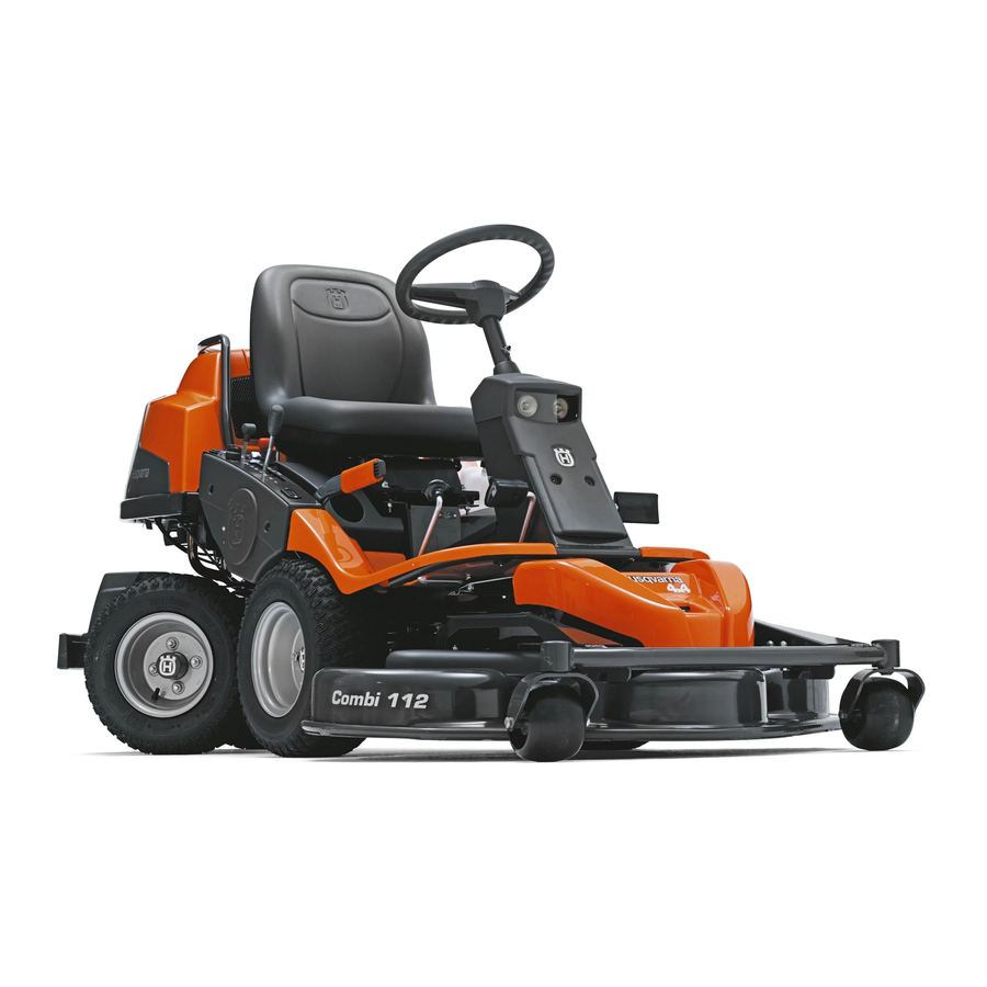
PRESENTATION Cutting unit Mechanical Lifting Lever for Cutting Unit R 418 Ts and R 418 Ts AWD can be equipped with three different cutting units. Combi 94, Combi 103, Combi 112 The lever is used as a backup lever to put the cutting unit in The Combi-unit, equipped with a BioClip-plug, finely chops either the transport or mowing position when hydraulic the cuttings to fertiliser. -
Page 14: Seat
PRESENTATION Seat Lights and power outlet The seat has a jointed attachment on the front edge and can be tipped forward. The seat can also be adjusted lengthways. To adjust move the lever under the front edge of the seat to the left, so that the seat can be moved forward or backwards to the required position. -
Page 15: Release Lever
Pull the controls to the end positions, do not use an intermediate position. Release lever R 418Ts AWD R 418 Ts AWD have one control for the front axle and one control for the rear axle. -
Page 16: Driving
Driving Cutting tips Before starting • Read the safety instructions and information concerning the placement of controls and functions before starting. • Perform daily maintenance before starting as set out in the Maintenance schedule. IMPORTANT INFORMATION The air intake grille in the engine cover behind the driver’s WARNING! Clear the lawn from stones and seat must not be blocked by, for example, clothing, leaves, other objects which can be thrown out by... -
Page 17: Starting The Engine With A Weak Battery
Driving Starting the engine with a weak 4 If the engine is cold move the choke lever backwards to its end position. battery WARNING! Lead-acid batteries produce explosive gases. Avoid sparks, open flames and smoking close to batteries. Always wear protective glasses in the vicinity of batteries. -
Page 18: Driving The Rider
Driving Driving the Rider It is important that the air pressure in both front wheels is equal, 60 kPa / 0,6 bar / 8.7 PSI, to produce an even cutting height. 1 Release the parking brake by first pressing down the parking brake pedal and then releasing it. -
Page 19: Braking
Driving Braking 3 When the Rider is at a standstill, press down the parking brake and push in the locking button. Release the drive pedals. The machine slows and is stopped by the drive system. Do not use the parking brake as the drive brake. -
Page 20: Maintenance
Maintenance Maintenance schedule The following is a list of the maintenance which should be conducted on the machine. For those points not described in this manual, visit an authorised service workshop. Daily Weekly At least Maintenance Maintenance maintenance maintenance once a year interval in hours before starting 100 250... - Page 21 If the machine is used daily it should be lubricated twice a week. Conducted by authorised service workshop. Only R 418Ts AWD first change after 8 hours X = Described in this operator's manual O = Not described in this operator's manual...
-
Page 22: Cleaning
Maintenance Cleaning Front cover Release the clip on the front hood and lift off the fender. Clean the machine directly after use. It is much easier to wash off grass cuttings before they dry. The front cover is secured to the unit frame with two hooks. Oily dirt can be removed using a cold degreasing agent. -
Page 23: Checking And Adjusting The Steering Wires
Maintenance Checking and adjusting the steering Adjusting the parking brake R 418Ts wires Check that the parking brake is adjusted correctly by placing the machine on a slope with the front and rear axles The steering is controlled by means of wires. -
Page 24: Checking And Adjusting Of Throttle Wire
Maintenance Checking and adjusting the choke 3 Remove the left-hand wing cover. wire If the engine is producing black smoke or is difficult to start then the choke wire (upper wire) may be incorrectly adjusted. If doubts arise, contact your service representative. If it is necessary to adjust the choke, proceed as follows: 4 Loosen the locking nuts. -
Page 25: Checking The Transmission's Air Intake
Maintenance Checking the transmission’s air Clean the filter by knocking it with care against a hard surface. Do not use compressed air to clean the filter. intake Replace the air filter if it is still dirty. If the paper filter is still dirty it should be replaced with a new one. -
Page 26: Cleaning The Engine And Muffler
Maintenance Cleaning the engine and muffler 5 Disconnect the cables from the bulbs. Keep the engine and muffler free from grass cuttings and dirt. Grass cuttings steeped in petrol or oil on the engine can increase the fire risk and impair cooling. Allow the engine to cool before cleaning. -
Page 27: Checking The Tyre Pressure
Maintenance Checking the tyre pressure Replacing the rear drive belt R 418Ts The tyre pressure should be 60 kPa (0.6 bar / 9 PSI) all round. Removal To improve driving the pressure on the rear tyres can be reduced to 40 kPa (0.4 bar/5.6 PSI). The maximum tyre 1 Lift up the cutting unit pressure is 100 kPa (1,0 bar/14 PSI). -
Page 28: Replacing The Hydraulic Pump's Drive Belt R 418Ts Awd
2 Pull the belt under the engine belt pulleys and fit it on the engine belt pulley. Replacing the hydraulic pump’s drive belt R 418Ts AWD 1 Remove the transmission cover. 2 Unhook the spring on the belt tensioner 3 Fit the belt on the hydrostatic transmission pulley. -
Page 29: Replacing The Centre Belt
Maintenance 5 Remove the cooling fan, it is held in place by a nut. 6 Fit the belt guide for the centre belt. 7 Fit the spring on the belt tensioner. 6 Pull the belt off of the pump's pulley. Pull the belt off of the engine's pulley and move it under the engine belt pulleys. -
Page 30: Replacing The Front Belt
Maintenance Replacing the front belt 2 Push the equipment frame down and place the catch against the frame. The entire belt is removed according to the following when a snow blade is to be attached to the machine. 1 Put the unit in the service position, see Service position for the cutting unit. -
Page 31: Removing The Cutting Unit
Maintenance Checking and adjustment of the 8 Secure the collet spring. cutting unit’s ground pressure To achieve the best cutting results the cutting unit should follow the underlying surface without pressing too hard against it. Pressure is adjusted using a screw and spring on each side of the Rider. -
Page 32: Adjusting The Parallelism Of The Cutting Unit
Maintenance Adjusting the parallelism of the Remove the bolt so the track rod is released in one end. cutting unit 1 Remove the front hood and right-hand fender. 2 Undo the nuts on the lift strut. 3 Unscrew the bolt holding the unit frame bracket. 3 Screw out (extend) the stay to raise the rear edge of the cover. -
Page 33: Service Position For The Cutting Unit
Maintenance Service position for the cutting unit WARNING! Observe caution to avoid trapping your hand. The cutting head can be placed in the service position to provide easy access for cleaning, repairs and servicing. In the 5 Remove the drive belt and place it in the belt holder. service position the cutting unit is raised and locked in the vertical position. -
Page 34: Checking The Blades
Maintenance Checking the blades To achieve the best mowing results it is important that the blades are undamaged and well-sharpened. Check that the blades’ attachment screws are tight. If the blades hit a foreign body such as a stone, they should be inspected before using them again. -
Page 35: Lubrication
Lubrication General Pedal system in the frame tunnel Lubricate the pedal system in the frame tunnel. Remove the ignition key to prevent unintentional movements during lubrication. • Remove the cover of the frame tunnel by loosening the screws (two on the steering servo housing). When lubricating with an oilcan, it ought to be filled with engine oil. -
Page 36: Driver Seat
Lubrication Driver seat Checking the engine’s oil level. Fold up the seat. Check the oil level in the engine when the Rider stands horizontal with the engine switched off. Do not check the oil Lubricate the lengthways adjustment runners with oilcan. with the engine running. -
Page 37: Lubricate The Hydrostatic Cable With Links
Lubrication Replacing the engine oil Remove the rubber casing and lubricate the hydrostatic transmission cable with oil. Open the engine cover. The engine oil should be changed the first time after 8 hours running time. It should then be changed after every 100 hours of running time. -
Page 38: Hydraulic Oil Filter Change
• Remove the transmission cover. • Unhook the spring (A) from the screw (B). R 418Ts Fill if necessary with engine oil SAE 10W/40 (class SF–CC). R 418Ts AWD Fill if necessary with oil Synthetic 10W/50 • Replace the transmission cover. -
Page 39: Troubleshooting Schedule
Troubleshooting schedule Problem Cause Engine does not start There is no fuel in the fuel tank Spark plug defective Faulty spark plug connections or interchanged cables Dirt in the carburettor or fuel line Starter motor does not turn over the engine Starter motor does not turn over the engine Battery flat Bad contact between the cable and battery... -
Page 40: Electrical And Hydraulic Systems
ELECTRICAL AND HYDRAULIC SYSTEMS Numbers correspond to: 7 Engine connectors 1 Microswitch, hydrostatic transmission 8 Main fuse 15 A 2 Microswitch, cutting unit 9 Fuse 7.5 A 3 Microswitch, seat 10 Switch for the power outlet 4 Ignition lock 11 Power outlet 5 Counter 12 Switch for the lights 6 Start relay... -
Page 41: Hydraulic System
ELECTRICAL AND HYDRAULIC SYSTEMS Hydraulic System Keep the hydraulic system clean. Bear in mind that: • Thoroughly clean before the top-up cap is opened or any connector loosened. • Use clean containers when topping up the oil. • Only use pure oil that has been stored in a sealed container. •... -
Page 42: Storage
Storage Winter storage Service At the end of the season, or if the machine is going to stand Low season is the most suitable time to perform a service or idle for more than 30 days, it should immediately be made overhaul of the machine in order to ensure high function ready for storage. -
Page 43: Technical Data
Technical data R 418Ts R 418Ts AWD Dimensions Length without cutting unit, cm/in 202 / 79,5 202 / 79,5 Width without cutting unit, cm/in 90 / 35,4 90 / 35,4 Height, cm/in 113 / 44,5 113 / 44,5 Unladen weight excluding cutting unit, kg/lb... - Page 44 1120 / 44.1 1220 / 48 Technical specifications for sound and vibration levels R 418Ts R 418Ts AWD Combi 94 Combi 103 Combi 112 Combi 94 Combi 103 Combi 112 Noise emissions (see note 2) Sound power level, measured dB (A)
-
Page 45: Ec-Declaration Of Conformity
EC-declaration of conformity (Applies to Europe only) Husqvarna AB, SE-561 82 Huskvarna, Sweden, tel.: +46-36-146500, hereby declares that Husqvarna R 418Ts and R 418Ts AWD from 2013’s serial numbers and onwards (the year is clearly stated in plain text on the rating plate with subsequent serial number), complies with the requirements of the COUNCIL’S DIRECTIVE:... - Page 48 Original instructions 1155354-26 ´®z+WCJ¶6y¨ ´®z+WCJ¶6y¨ 2012-12-18...