
Related Manuals for BBQ 4


Summary of Contents for BBQ 4
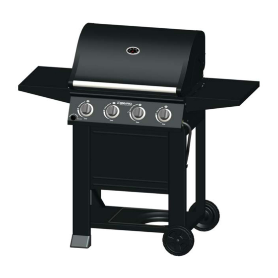
- Page 1 OWNER’S MANUAL BBQ PRO 4 BURNER GAS GRILL Product code: 23770 / 0-05307038-9 Item: 146.23770310 UPC code: 182995000903 Date of purchase:...
-
Page 2: Installation Safety Precautions
• Grill installation must conform with local codes, or in their absence of local codes, with either the National Fuel Gas 4. If odor continues, keep away from the Code, ANSI Z223.1/ NFPA 54, Natural Gas and Propane appliance and immediately call your gas Installation Code, CSA B149.1, or Propane Storage and... -
Page 3: Table Of Contents
One Year Full Warranty on BBQ PRO Grill Product Record Information . . . If this grill fails due to a defect in material or workmanship within one year from the date of purchase, call 1-800-4-MY Installation Safety Precautions ..2 HOME ®... -
Page 4: Use And Care
Never leave an LP tank inside directory under “Gas Companies” for nearest certified LP a vehicle which may become overheated by the sun. dealers. • Do not store an LP tank in an area where children play. 4 • 146.23770310... - Page 5 OPD safety feature-equipped tank as described in the full stop. "LP Tank" section of this manual. 4. Remove the protective cap from LP tank valve. Always use • Always keep new and exchanged LP tanks in upright position cap and strap supplied with valve.
- Page 6 There is a major leak at the connection. Correct before proceeding by calling Sears for replacement parts at 1-800-4-MY-HOME ® Hold coupling nut and regulator 4.Brush soapy solution onto areas where bubbles are shown in as shown for proper connection to LP tank valve. picture below: ▲...
- Page 7 Electronic Ignition button. • NEVER attempt to light burner with lid closed. A 4. If ignition does NOT occur in 5 seconds, turn Ignition Burner buildup of non-ignited gas inside a closed grill is control knob OFF, wait 5 minutes, and repeat the lighting hazardous.
-
Page 8: Parts List
"Troubleshooting" if no click or spark. and stay lit. Valve Check 4. Light other burners follow with steps 3. • Important: Make sure gas is off at LP cylinder before checking valves. Knobs lock in OFF position. To check valves, first push in knobs and release, knobs should spring back. -
Page 9: Control Knob
3. Remove carryover tubes from rear of burners. IMPORTANT: Always ensure that the venturi burner tubes 4. Remove cotter pin from rear of burners. are clean. A venturi burner tube has a narrow area in 5. Carefully lift each burner up and away from valve openings. - Page 10 USDA Meat and Poultry Hotline at 1 Burner Cooking 1-800-535-4555 (In Washington, DC (202) 720-3333, 10:00 am Cook with direct or indirect heat. 4:00 pm EST). Best for smaller meals or foods Consumes less fuel. How To Tell If Meat Is Grilled Thoroughly Indirect Cooking Instructions •...
-
Page 11: Parts List
If you are missing hardware or have damaged parts after unpacking grill, call 1-888-287-0735 for replacement. To order replacement parts after using grill, call 1-800-4-MY-HOME ® NOTE: Some grill parts shown in the assembly steps may differ slightly in appearance from: Those on your particular grill model. -
Page 12: Parts Diagram
PARTS DIAGRAM 12 • 146.23770310... - Page 13 BEFORE ASSEMBLY PLEASE READ AND FOLLOW THE INSTRUCTIONS BELOW TO CORRECTLY UNPACK GRILL PARTS FROM SHIPPING BOX. Step 1: Open shipping box by slicing down its edges with a box cutter, take out hardware pack, manual, right leg assembly, bottom shelf from top. Next remove left leg assembly, back brace from front. Remove all packing materials, take out axle rod, grease cup and grease cup bracket from left Styrofoam, take out front panel from right Styrofoam.
- Page 14 BEFORE ASSEMBLY Step 2: Open grill lid, take out the three boxes packed in it. Remove all packing materials, take out the parts from these boxes. 14 • 146.23770310...
-
Page 15: Assembly
ASSEMBLY PLEASE READ AND FOLLOW THE INSTRUCTIONS CAREFULLY STEP BY STEP Tools Required: Adjustable wrench (not provided) Screwdriver (not provided) 7/16” Combination wrench (not provided) The following hardware is provided in blister pack: Item Description Figure Quantity M4X10 screw 15 pcs M6X13 screw 16 pcs M6 compression washer... - Page 16 Bottom Shelf to Legs □ Place bottom shelf end with cut out hole for LP cylinder between legs with axle holes. Attach to right and left leg assemblies with (6) M4x10 screws. □ Tighten securely. Right Leg Assembly M4x10 screw 6 pcs Left Leg Assembly Front Rear...
-
Page 17: Leg Extender, Front
□ Turn assembly upside down. □ Attach bottom shelf to four legs with (4) M6x13 screws. □ Insert axle rod through wheel, axle rod spacer, two right legs, another axle rod spacer and other wheel. Attach with (1) Axle washer, nut and hitch pin. - Page 18 □ Stand cart upright. □ Attach back brace to top of cart with (4) M4x10 screws. □ Attach front panel to line up with top of cart with (3) M4x10 screws and leave the bottom hole of left front leg uninstalled.
- Page 19 This step requires two people to lift and position grill head onto cart. □ Carefully lower the grill head onto the cart. Make sure the regulator hose is hanging outside the cart. Attach with (4) M6x13 screws and (4) M6 compression washers. M6x13 screw 4 pcs M6 compression washers 4 pcs 146.23770310...
- Page 20 - From inside to outside of firebox with (2) M6x13 screws and (2) M6 compression washers. - From outside to inside of firebox with (2) M6x13 screws. Repeat above step for the right side shelf. □ M6x13 screw 8 pcs M6 compression washers 4 pcs 20 • 146.23770310...
- Page 21 Heat Diffusers, Cooking Grates and Warming Rack □ Place heat diffusers over burners. Diffusers will fit in firebox in either direction. Fit tabs in firebox front through slots in diffuser tips. Fit diffuser tips beside tabs in firebox rear. □ Place cooking grates onto grate rests.
-
Page 22: Grease Cup
Grease Cup Clip, Grease Cup and LP tank □ Hang grease cup clip from bottom of firebox and place grease cup into grease cup clip. □ Secure the regulator hose to the right front leg with hose fixed pin and R cotter pin. □... -
Page 23: Troubleshooting
Main Burners: • Tip of electrode should be pointing toward gas port opening on burner. The distance should be 1/8” to 1/4”. Adjust if necessary. • Wire and/or electrode covered with • Clean wire and/or electrode with rubbing alcohol and clean swab. - Page 24 Troubleshooting (continued) Problem Possible Cause Prevention/Solution Burner(s) will not light ELECTRONIC IGNITION: • See Section I of Electronic Ignition System. using ignitor. • No spark, no ignition noise. (See Electronic Ignition • See Section II of Electronic Ignition System. Troubleshooting also) •...
- Page 25 Troubleshooting - Electronic Ignition Problem (Ignition) Possible Cause Preventio SECTION I • Check battery orientation. • Install battery (make sure that “+” and “-” No sparks appear at • Battery not installed connectors are oriented correctly, with “+” end up any electrodes when properly.
- Page 26 MANUAL DE PROPIETARIO BBQ PRO PARILLA DE GAS CON 4 HORNILLAS Código de producto: 23770 / 0-05307038-9 Item: 146.23770310 Código de UPC: 182995000903 Fecha de compra:...
-
Page 27: Por Su Propia Seguridad
• La instalación de la parrilla debe cumplir con las disposiciones de los códigos locales, o, en su defecto, con el National Fuel Gas Code (o 4. Si persiste el olor, aléjese del aparato y llame Código nacional sobre gases combustibles), y las normas NFPA 54 inmediatamente al proveedor local de gas o a los / ANSI Z223.1 y Natural Gas and Propane Installation Code (Código... -
Page 28: Garantía Limitada Bbq Pro
GARANTIA LIMITADA Por su propia seguridad ..26 Garantía completa de un año para la parrilla BBQ PRO Centro de servicio para parrillas..26 Información de inscripción de la garantía . . . -
Page 29: Uso Y Mantenimiento
Tanque de gas propano UOS Y MANTENIMIENTO • El tanque de gas que use con su parrilla debe cumplir los PELIGRO siguientes requisitos: • Use únicamente tanques de gas que tengan las siguientes medidas obligatorias: 12" (30.5 cm) (diámetro) x 18" (45.7 cm)(altura), con una capacidad máxima de 20 lb. - Page 30 • Siempre mantenga los tanques de gas, nuevos y de repuesto, 4. Retire la tapa protectora de la válvula del tanque de gas. Use en posición vertical durante su uso, su transporte o su siempre la tapa y la tira que vienen con la válvula.
- Page 31 Corrija esta situación antes de Sostenga la tuerca de unión y el continuar. regulador, como se ilustra, para 4. Aplique solución jabonosa con la brocha, en las áreas conectarlos bien a la válvula del marcadas con un círculo en la ilustración que sigue. tanque.
- Page 32 Encendido electrónico. cerrada. Las acumulaciones de gas no encendido en las 4. Si NO se enciende en 5 segundos, gire la perilla de control del quemador del lado izquierdo a la posición de APAGADO, espere 5 parrillas tapadas son peligrosas.
- Page 33 (como se ilustra más abajo). posición original. De lo contrario, cambie la unidad de la válvula antes 4. Oprima y gire la perilla del QUEMADOR DE ENCENDIDO a la de usar la parrilla. Gire las perillas a la graduación BAJA y luego posición de.
- Page 34 3. Retire los tornillos y los tubos de arrastre de la parte posterior de los quemadores. 4. Retire los tornillos y las arandelas para desconectar el quemadordel soporte de la cámara de combustión. 5. Retire los tornillos para desmontar el electrodo del quemador. El electrodo debe permanecer en la cámara de combustión.
- Page 35 Cocción indirecta Seguridad con los alimentos Las aves y los cortes grandes de carne se cocinan lentamente a la La seguridad con los alimentos es una parte muy importante del perfección en la parrilla por calor indirecto. El calor de los disfrute de su parrillada al aire libre.
-
Page 36: Lista De Piezas
Tubo de llama Carry Over 40800022 Si falta o está dañada alguna pieza, llame al Quemador principal 40700125 ® 1-800-4-MY-HOME , para su reposición. Gire la varilla, Tapa 50300207 No ilustrado Si le falta el hardware o que han deteriorado las partes después de desempaquetar parrilla, llame al... -
Page 37: Vista Esquemática De Las Piezas
DIAGRAMA DE PARTES DIAGRAMA DE PARTES 36 • 146.23770310... -
Page 38: Antes De La Asamblea
ANTES DE LA ASAMBLEA POR FAVOR LEA Y SIGA LAS INSTRUCCIONES A CONTINUACIÓN PARA DESEMPAQUETAR CORRECTAMENTE LAS PIEZAS DE LA PARRILLA DE CAJA. Paso 1: Caja abierta por rebanar hacia abajo los bordes con un cúter, Extraiga el paquete de hardware, manual, Asamblea de la pierna derecha, estante inferior desde la parte superior. - Page 39 ANTES DE LA ASAMBLEA Paso 2: Tapa de la parrilla abierta, sacar las tres casillas incluidas en él. Retire todos los materiales de embalaje, Saque las piezas de estos cuadros. 38 • 146.23770310...
- Page 40 VISTA ESQUEMATICA DE LAS PIEZAS POR FAVOR LEA Y SIGA LAS INSTRUCCIONES CUIDADOSAMENTE PASO A PASO Herramientas necesarias para el armado: Llave inglesa (que no viene incluida) Destornillador (que no viene incluida) Llave mixta de 7/16” (que no viene incluida) Mazo de goma El hardware siguiente se presenta en blister: Descripción Figura...
-
Page 41: Asamblea
Estante inferior para las piernas □ Coloque el extremo de estante inferior con corte un agujero para cilindro de gas LP, entre las piernas con los agujeros del eje. Adjuntar a las Asambleas de la pierna derecha e izquierda con los dos tornillos M4x10 (6). - Page 42 Extensores de pierna al carro y ruedas □ Voltee Asamblea. □ Fije la repisa inferior a cuatro patas con tornillos de M6x13 (4). □ Insertar barra del eje a través de la rueda y la otra rueda. Fije con pasador de enganche, la tuerca y la arandela de eje (1).
- Page 43 □ Póngase de carro pie. □ Conecte soporte posterior a la parte superior del carro con los dos tornillos M4x10 (4). □ Ate panel frontal al alinearse con la parte superior del carro con (3) tornillos M4x10 y dejar el orificio inferior de la pata delantera izquierda desinstalado.
- Page 44 □ Este paso requiere dos personas levantar y colocar la cabeza de la parrilla en el carro. □ Cuidadosamente baje la cabeza de la parrilla en el carro. □ Asegúrese que la manguera del regulador está colgando fuera del carro. Fije con tornillos de M6x13 (4) y (4) arandelas de compresión de M6.
- Page 45 - Desde dentro hacia fuera de cámara de combustión con tornillos de M6x13 (2) y (2) arandelas de compresión de M6. - De fuera para dentro de la cámara de combustión con M6x13 (2) tornillos. □ Repita el paso para el estante de la derecha. M6x13 tornillo 4 pcs M6 arandelas de compresión 4 pcs 44 • 146.23770310...
- Page 46 Difusores de calor Cooking Grates y Parrilla de calentamiento □ Coloque difusores de calor sobre los quemadores insertando las lengüetas en las ranuras en la parte delantera y la parte posterior de la cámara de combustión. □ Coloque rejillas para cocinar sobre la parrilla descansa. □...
- Page 47 Clip de taza de grasa Tanque para grasa y LP □ Colgar clip de taza de grasa de la parte inferior de la cámara de combustión y coloque la taza de la grasa en clip de taza de grasa. □ Fije la manguera del regulador a la pata delantera derecha con manguera fijada pin y pasador de R. □...
-
Page 48: Resolución De Problemas
"chispas de la quebradura”. • La punta del electrodo debe estar orientada hacia el agujero de • La punta del electrodo no está en combustión del quemador. La distancia debe ser de 1/8" a 1/4". posición correcta. Ajústela si es necesario. - Page 49 Resolucion de problemas (continuacion) Problema Causas probables Medidas de prevención / solución • Limpie el cable y el electrodo con alcohol de frotar y un hisopo El quemador o los • El cable o el electrodo está cubierto con limpio. quemadores no se restos de comida.
- Page 50 Resolución de problemas – Encendido electrónico Medidas de prevención / solución Problema (encendido) Causas probables Procedimiento de revisión Preventio Causas probables • Revise la orientación de la • Instale la pila (verifique que los polos “+” y “–” • La pila no está SECCIÓN I pila.
- Page 51 Made in/Hecho en CHINA Distributed by Sears, Roebuck and Co., Hoffman Estates, IL 60179 See our extensive assortment of outdoor living products On-line at www.sears.com and www.kmart.com...