
Related Manuals for QSC DSP-4


Summary of Contents for QSC DSP-4
- Page 1 DSP-4 Digital Signal Processor Amplifier Accessory Hardware Manual *TD-000103-00* TD-000103-00 Rev.B...
- Page 2 While QSC has endeavored to develop and produce the most dependable and robust Digital Signal Processor (DSP) audio product for your use, due to the unlimited and potentially destructive (to the sound system) configurations that may be applied to the DSP by the user, QSC cannot be held responsible for damages resulting from any deviation or failure by the user to strictly follow the recommendations set forth in the owner’s manual for the integration of the DSP-4 and Signal Manager software with your sound system.
-
Page 3: Table Of Contents
Maintenance, Warranty & QSC Contact Information........26 © Copyright 2002, QSC Audio Products, Inc. QSC® is a registered trademark of QSC Audio Products, Inc., Costa Mesa, CA “QSC” and the QSC logo are registered with the U.S. Patent and Trademark Office... -
Page 4: Overview
From all of us at QSC Audio, thank you for your purchase. Be sure Physically, the DSP-4 is a small module that “piggybacks” to check our website at http://www.qscaudio.com for the onto the back panel of the specified QSC amplifiers. -
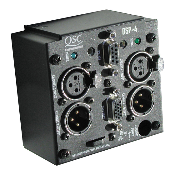
Page 5: Connector & Indicator Descriptions, Illustrations
XLR’s. If not using the DataPort for inputs, these anced male XLR’s. These outputs provide post- are where you connect the line-level audio inputs DSP (processed) signal from the DSP-4 for down- to the DSP-4. stream devices (amplifiers, monitoring busses,... -
Page 6: Rear Panel
Connector & Indicator Descriptions Rear Panel DATAPORT (unlabeled): This is the “output” DataPort. If the DSP-4 is directly mounted on a 2-RU, 2 channel QSC DataPort equipped amplifier, this connector plugs into the amplifier’s DataPort con- nector. If used with 3-RU, 4- or 8-channel QSC DataPort... -
Page 7: Functions And Features
DSP-4 Hardware Features The full set of features is available on QSC DataPort equipped amplifiers connected to the DSP module via the DataPort connector (direct-connect or remote-mount with DPX-2 cable). “V2” DataPorts and non-QSC amplifiers do not support Output Power Limiting. -
Page 8: Block Diagram
INTRODUCTION- Block Diagram and Details This portion of the introduction provides some of the technical details of the DSP-4. Input Stage- Inputs are electronically balanced and RF filtered. The input sensitivity is software-selectable and any large signals are prevented from destroying the A-to-D by a diode. -
Page 9: Unpacking
Unpacking It is recommended that you keep the original packing material for reuse in the rare event that service be required for your DSP-4. If service is required, and the original packing material is not available, insure that the DSP-4 is adequately protected for shipment (strong box of appropriate size , sufficient packing material). -
Page 10: Signal Manager Software Installation
Software Installation In order to use your DSP-4 module, you will need to install the QSC Audio Signal Manager software on your PC. The module is configured to pass full range audio unattenuated from input-to-output as shipped from the factory. You must use the software to configure the module as desired. -
Page 11: Mounting To Qsc Dataport Equipped Amplifiers
•Clip limiter setting does not matter •Mode set as required (stereo, bridge mono, parallel) Align the DataPort plug on the back of the DSP-4 with the DataPort jack on the back of the amplifier and gently push the module to seat the connector. -
Page 12: Mounting To The Accessory Remote Mounting Bracket
INSTALLATION- Remote mounting (4-ch., 8-ch. Powerlight & non QSC amp’s) The DSP-4 module requires “remote” mounting when used with the 4- and 8-channel CX, 4-channel DCA, Powerlight, and non-QSC amplifiers. If you have an amplifier that requires “remote” mounting, you need to: Obtain the Accessory Remote Mounting Bracket. -
Page 13: Connecting To The Dataport Of The Dsp-4
Alternatively, the DataPort connection can be used ONLY for control and monitoring, while the audio is input via the XLR inputs. If using the DSP-4 in this manner, do not apply audio via the DataPort as it will be mixed with the XLR audio input signals. -
Page 14: Connecting Xlr Audio Inputs And Outputs
DataPort-equipped amplifier via the rear-panel DataPort. The maximum number of QSC amplifiers that can be connected to the DSP-4’s outputs (including the output DataPort) is five. This ensures THD stays below 0.1%. The effect on output level signal strength is about -3 dB when five QSC amplifiers are daisy chained. -
Page 15: Connecting To Rs-232 Port
DSP-4 setup and programming takes place via the RS-232 port. Any time setup changes are required to the DSP-4, it must be connected to its host computer through the RS-232 port. If “real-time” control of the DSP-4 is required, the RS-232 port connection must be maintained. -
Page 16: Connection To Accessory External Dc Power Supply
When the module is used with QSC amplifiers that do not provide +15 VDC through their DataPort connection OR is used with non-DataPort amplifiers, power must be supplied to the DSP-4 from an external power supply. All non-QSC amplifier applications require use of the DPX-1 accessory external supply. Contact QSC’s Technical Services Department or your QSC representative for more information. -
Page 17: Daisy-Chaining The Dsp-4 Outputs
Daisy chaining the DSP-4 outputs to additional amplifiers The DSP-4 has two XLR audio outputs, one for each channel. These outputs may be used for daisy-chaining the post-DSP signal to other amplifiers or for monitoring purposes. The XLR outputs may be used for daisy- chaining even when the DataPorts are used for input/output. -
Page 18: General Guidelines For Freely Configurable Dsp
The DSP-4 is configured (programmed) by using the included Signal Manager software. The software must be installed on your PC and the PC must be connected to the DSP-4 using a 9-pin serial cable and an available COM port. Once programmed, the module can operate without any connection to the computer. -
Page 19: Special Information About Saving Dsp-4 Configurations
“just the math”. If building a new configuration from scratch, when you apply it to the DSP-4 you will also be prompted to save it to disk as a Configuration file (*.cfg). The path for this Configuration file is then associated with the compiled information that is applied to the DSP-4. -
Page 20: Specifications
SPECIFICATIONS AUDIO PERFORMANCE Audio converters 24-bit resolution, 48 kHz sampling rate Frequency response at 3 dB below full scale input voltage 20 Hz–10 kHz ±0.3 dB (XLR outputs) 20 Hz–20 kHz ±0.7 dB (XLR outputs) 20 Hz–20 kHz±0.2 dB (DataPort outputs) Distortion <0.01% typical THD+N @ +4 dBu out, 20 Hz–20 kHz Delay (throughput) - Page 21 HD-15 connector, 1 female “input” DataPort and 1 male “output” DataPort. Cables are of proprietary construction and are available from QSC’s Technical Services Department. No “output” cable required for QSC amps that support direct mounting. Amplifiers per DSP-4 1 two-channel amplifier per DSP-4 RS-232 PORT RS-232 port is used for “downloading”...
- Page 22 The Digital Signal Processor (DSP) shall provide two independent Contact Closure I/O—The DSP shall provide a trigger input channels of DSP for signal delivery to QSC DataPort equipped usable for contact-closure (or other) purpose which shall power amplifiers. The processing shall be distributed with the DSP be CMOS &...
-
Page 23: Dataport Pinout
DataPort feature is specific to I- MON Ch. 1 and Encode 2 QSC products and not intended for inter- Clip/Protect Ch. 1 face to other manufacturer’s equipment. Hard Ground Ch. -
Page 24: Rs-232 Pinout
APPENDIX- RS-232 Port Pinout & Connector P-N’s RS-232 PINOUT: The diagram below shows the pin assignments for the RS-232 connector on the DSP-4. Note that Pin #9 is used for Contact Closure function (normally not used in RS-232). Signal Description... -
Page 25: Application Information
•Full feature set, Direct-mounting, No external power required, No special interconnect cables required for the following QSC power amplifiers with serial numbers of 0899XXXXX and later, where the first four digits of the serial number are the MMYY datecode :... -
Page 26: Maintenance, Warranty & Qsc Contact Information
If the DSP-4 is returned to the factory for service, it should be sent in the proper QSC carton. If you did not save the original carton, ask TELEPHONE NUMBERS: your QSC dealer for one or call QSC to have one sent to you. - Page 28 PH: (714) 754-6175 FAX: (714) 754-6174 © Copyright 2002, QSC Audio Products, Inc. QSC® is a registered trademark of QSC Audio Products, Inc., Costa Mesa, CA “QSC” and the QSC logo are registered with the U.S. Patent and Trademark Office...