Table of Contents
Advertisement
Advertisement
Table of Contents

Related Manuals for Peavey 3120


Summary of Contents for Peavey 3120
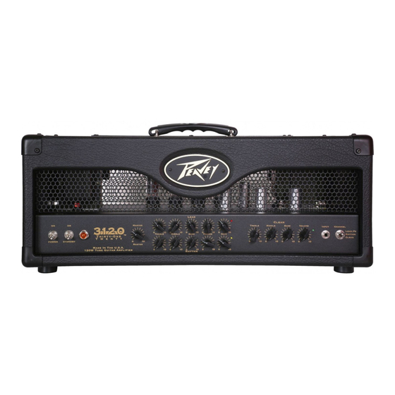
- Page 1 3120 120 watt all tube 3 channel guitar amplifier Operating Manual www.peavey.com...
- Page 2 Intended to alert the user to the presence of uninsulated “dangerous voltage” within the product’s enclosure that may be of sufficient magnitude to constitute a risk of electric shock to persons. Intended to alert the user of the presence of important operating and maintenance (servicing) instructions in the literature accompanying the product.
- Page 4 Designed to work equally well into 4, 8, or 16-Ohm loads, matching this monster to a cabinet is limited only by your imagination. with footswitchable channel and effects loop, the 3120 lets you keep your hands on the guitar - and your eyes on your dream.
-
Page 5: Front Panel
FRONT PANEL POWER SWITCH This two-way toggle switch applies mains power to the unit. The amber POwER STATUS LAMP (3) will illuminate when this switch is in the ON position. STANDBY SWITCH This two-way toggle switch allows the amp to be placed in the STANDBY mode. In the STANDBY position the tubes stay hot but the amplifier is not operational. - Page 6 GAIN Rhythm and Lead This control, on both the channels, controls the input volume level of the channel. Rotating this control clockwise will increase the amount of preamp distortion and sustain. (10) CHANNEL ACTIVATION LEDs These indicators signify which channel is active. Lead channel activation illuminates the red LED;...
-
Page 7: Rear Panel
A high damping factor (TIGHT) reduces cone vibration quicker than a low (LOOSE) factor. This switch works much like the resonance and presence controls on other Peavey amps, if those controls were turned simultaneously. If the DAMPING SWITCH is changed, the volume of the amp will also change and require re-adjustment. - Page 8 If hum or noise is noticed coming from the speaker enclosure(s), the switch may be placed in the “+” or “-” position to minimize hum/noise. If changing the polarity does not alleviate the problem, consult your authorized Peavey dealer, the Peavey factory, or a qualified service technician.
- Page 9 FOOTSWITCH (30) CABLE CONNECTOR This 7-pin DIN connector is provided for connecting the footswitch to the amplifier REMOTE SWITCH (20) via the cable included in the carton. Connections at the switch and the amplifier should be made before the amp is powered up. (31) Lead / Rhythm SELECTOR This switch selects between the Rhythm and Lead channels on the ampli- fier.
-
Page 10: Specifications
3120 SPECIFICATIONS Power Amplifier Section: Rhythm Channel: Nominal Input Level: -80 dBV, 0.1 mV RMS Minimum Input Level: -90 dBV, 0.03 mV RMS Tubes: Four EL34's with 12AX7 driver Lead Channel: Nominal Input Level: -80 dBV, 0.1 mV RMS Rated Power and Load: Minimum Input Level: -90 dBV, 0.03 mV RMS... - Page 12 NOTES:...
- Page 13 Logo referenced in Directive 2002/96/EC Annex IV (OJ(L)37/38,13.02.03 and defined in EN 50419: 2005 The bar is the symbol for marking of new waste and is applied only to equipment manufactured after 13 August 2005...
- Page 14 Features and specifications subject to change without notice. Peavey Electronics Corporation • 5022 Hartley Peavey Drive • Meridian • MS • 39305 (601) 483-5365 • FAX (601) 486-1278 • www.peavey.com ©2008 Printed in the U.S.A. 9/08 80304881...