Table of Contents
Advertisement
INSTRUCTIONS
IX81
MOTORIZED INVERTED
RESEARCH MICROSCOPE
This instruction manual is for the Olympus Motorized Inverted Research Microscope Model IX81.
To ensure the safety, obtain optimum performance and to familiarize yourself fully with the use of
this microscope, we recommend that you study this manual thoroughly before operating the
microscope. Retain this instruction manual in an easily accessible place near the work desk for
future reference.
A X 7 3 2 0
Advertisement
Table of Contents

Related Manuals for Olympus IX81


Summary of Contents for Olympus IX81
- Page 1 MOTORIZED INVERTED RESEARCH MICROSCOPE This instruction manual is for the Olympus Motorized Inverted Research Microscope Model IX81. To ensure the safety, obtain optimum performance and to familiarize yourself fully with the use of this microscope, we recommend that you study this manual thoroughly before operating the microscope.
-
Page 3: Table Of Contents
Note on operation in stand-alone mode When the IX81 motorized revolving nosepiece is rotated in stand-alone mode (without a PC), automatic es- cape movement of an objective (prevention of interference between the objective and stage) is not performed. - Page 5 IX81 4-6 Condenser ......................................23-25 Centering the Condenser Using the Aperture Iris Diaphragm Flipping Up the Condenser Holder 4-7 Objectives ......................................26-27 Oil-Proof Cap (UIS Series only) Adjusting the Correction Collar Using Immersion Objectives OTHER OBSERVATION METHODS 28-37 5-1 Phase Contrast Observation ..........................28-31 5-2 Differential Interference Contrast Observation ................
- Page 6 The IX81 microscope can be used in stand-alone mode (operated from the U-HSTR2 hand switch) or can operated from a PC when the IX2-BSW software (Ver. 01.03, compatible with Windows 2000/Me) is installed in the PC. Be sure to prepare the U-ZPCB (T2) Z-board and attach it to the IX81, and set the DIP switch (see page CAUTION 50) before connecting the IX2-UCB control board to the IX81.
-
Page 7: Safety Precautions
IX81 Releasing the Transport Lock of the Light Path Selector # Never attempt to operate the light path selector without removing the transport lock knob 5. Otherwise, the light path selector mechanism may be damaged. · Rotate the knob counterclockwise to remove it. - Page 8 Designated Bulb 12V100WHAL-L (PHILIPS 7724) 11. Always use the power cord provided by Olympus. If no power cord is provided, please select the proper power cord by referring to the section “PROPER SELECTION OF THE POWER SUPPLY CORD” at the end of this instruction manual.
- Page 9 IX81 Safety Symbols The following symbols are found on the microscope. Study the meaning of the symbols and always use the equipment in the safest possible manner. Symbol Explanation When raising or lowering the motorized revolving nosepiece, be careful not to have your finger or hand caught by the mechanism.
-
Page 10: Maintenance And Storage
6. Restrictions in TV observation @The following combinations are not permitted in consideration of the optical performance. · IX2-SPT + PE4X + U-PMTVC on the side port · IX2-SPT + PE5X + 1X magnification changer + U-PMTV1X on the side port ·... -
Page 11: Module Nomenclature
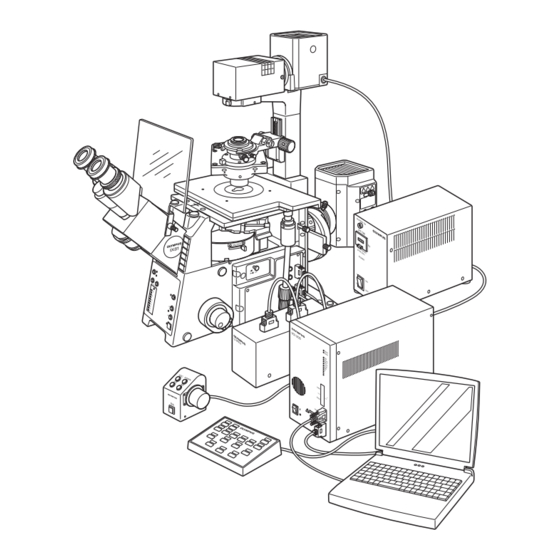
}The modules shown below are only the representative modules. As there are other modules which can be combined with the microscope but are not shown below, please also refer to the latest Olympus catalogues or your dealer. For information on the modules marked with “*", refer to their instruction manuals. - Page 12 CONTROLS }If you have not yet assembled the microscope, read Chapter 9, “ASSEMBLY” (pages 49 to 58). · The illustration shows the system composed of modules enclosed in · For the reflected light fluorescence modules including the IX2-RFACA, IX2-RFA, U-LH100HG and IX2-UCB/U-HSTR2, refer to their separate instruction manuals.
- Page 13 IX81 Left Side View of Microscope Frame Allen wrench and optical element centering knob (x 2) WHN10X/WHN10X-H storage position (Rear panel) Allen screwdriver storage position (Rear panel) U-BI90CT Diopter adjustment ring (Page 18) Interpupillary distance adjustment scale (Page 18) CT turret (Page 19)
- Page 14 Plain Stage Mechanical Stage IX2-SP IX-MVR Manipulator mounting screw holes M6 screw (x 6) IX-MVR mounting screw holes (Page 52) (On both sides) Cross Stage Y-axis knob IX-SVL2 X-axis knob UCD Adapter IX-ADUCD Y-axis knob X-axis knob LWD Universal Condenser IX2-LWUCD Condenser height fine }This is a manually controlled condenser.
- Page 15 Z-focusing motor ON/OFF OFF: Electrical noise reduction Escape/return objective Shutter IN/OUT Condenser top lens IN/OUT Not used with the IX81. Up/down operation for brightness ad- The function name can be written justment, objective, etc. in the blank area using an oil-ink pen.
-
Page 16: Transmitted Light Brightfield Observation Procedure
TRANSMITTED LIGHT BRIGHTFIELD OBSERVATION PROCEDURE }The following flow shows the operating procedure for the transmitted light brightfield observation which is the basic obser- vation method of this microscope. The operating procedures for phase contrast observation and DIC observation will be described separately in Chapter 5, “OTHER OBSERVATION METHODS”... - Page 17 IX81 The button functions shown below are the initial setups at the moment the PC is started up. Controls with numbers inside are not available when the U-FH focus adjustment knob unit is in use. } Make a photocopy of the observation procedure pages and post it near your microscope.
-
Page 18: Using The Controls
USING THE CONTROLS 4-1 Microscope Frame Voltage Indication (Fig. 4) }Set the main switch of the IX2-UCB control box to “ I ” (ON), then press the transmitted light ON-OFF button 1 to ON. 1. Press the light intensity control button 2 to increase the voltage and make illumination brighter. -
Page 19: Magnification Change
(IX2-CA2) by the manufacturer operation. Fig. 5 Motorized Revolving Nosepiece # When the IX81 motorized revolving nosepiece is rotated in stand-alone mode, automatic escape movement of an objective is not performed. Therefore, let the motorized revolving nosepiece escape once before turning the nosepiece. -
Page 20: Focusing Block
4-2 Focusing Block }The same effect as the focusing knob on the microscope frame can also be obtained using the U-FH focus adjustment knob unit. However, when the microscope is used stand-alone while the cable to the U-FH is connected, the control used for focus adjustment is switched automatically to the focus adjustment knob on the U-FH. -
Page 21: Stage
IX81 4-3 Stage Placing the Specimen (Figs. 8 to 10) With the IX2-SFR or IX-SVL2 Stage (Fig. 8) Place the specimen on the center of the stage. }In the case of a slide glass specimen, plate the specimen with the cover glass facing down. -
Page 22: Moving The Specimen
Moving the Specimen (Fig. 11) With the IX2-SFR or IX-SVL2 Stage To move the specimen to a desired position, rotate the X-axis knob 1 and Y-axis knob 2. }When the index mark on the upper stage is aligned with the index line 3 provided on the substage, the center of the stage center plate aperture is almost in the center of the optical axis. -
Page 23: Observation Tube
IX81 4-4 Observation Tube Adjusting the Interpupillary Distance (Fig. 14) While looking through the eyepieces, adjust the binocular vision until the left and right fields of view coincide completely. The index dot · indicates the interpupillary distance. }Note your interpupillary distance so that it can be quickly duplicated. -
Page 24: Using Eyepiece Micrometer Disks
(Fig. 20) 1. To use the CT turret 1, rotate the knurled ring with a finger to select the setting corresponding to the indication (0-CT-0-S). (Set the magnification selector knob on the IX81 microscope frame to 1X.) Turret Application Indication... -
Page 25: Adjusting The Tilt (U-Tbi90 Only)
IX81 Adjusting the Tilt (U-TBI90 Only) (Fig. 21) }Adjust the height and tilt of the observation tube to obtain the most com- fortable viewing position. Holding the binocular section with both hands, raise or lower it to the desired position. -
Page 26: Mounting Filters
Mounting Filters (Figs. 23 to 25) }45 mm diameter, maximum 6 mm thick filters can be mounted. Various filters, such as the provided frosted filter, color temperature conversion filter (LBD), green interference filter (IF550) and ND filter can be mounted. 1. -
Page 27: Using The Field Iris Diaphragm
IX81 Using the Field Iris Diaphragm (Figs. 26 & 27) }The field iris diaphragm lever 1 is used to adjust the diameter of the illumination beam in accordance with the objective in use. Adjust the diaphragm so the field of view is circumscribed by the field iris diaphragm to exclude stray light and improve the contrast of images. -
Page 28: Condenser
4-6 Condenser Centering the Condenser (Figs. 30 & 31) With the IX2-LWUCDA2/IX2-LWUCD Universal Condenser or IX-ULWCD Condenser 1. Rotate the turret 1 (either manually or electrically) to select the “BF” brightfield observation (with which no optical element is engaged in the light path). - Page 29 IX81 With the U-UCD8 Universal Condenser (Fig. 31) # For operation of the U-UCD8, refer to the instruction manual provided with it. This condenser is used upside down, so the optical elements may fall off if shock is applied. Use caution particularly when flipping up the condenser holder.
-
Page 30: Flipping Up The Condenser Holder
Using the Aperture Iris Diaphragm (Fig. 32) 70-80% }In general, the potential resolving power of an objective is fully utilized if the 30-20% diaphragm is stopped down to correspond with the numerical aperture (N.A.) of the objective. }Depending on the specimen, image contras or focal depth in observa- tion or photomicrography may be improved by keeping the aperture iris diaphragm stopped down a little. -
Page 31: Objectives
IX81 4-7 Objectives Oil-Proof Cap (UIS Series only) (Fig. 34) }By mounting the oil-proof cap (Type C1 or C2) on the tip of the applicable objective, you can prevent penetration of immersion oil or water into the objective. This will enable the objective to achieve its original performance, so be sure to always mount the cap. -
Page 32: Using Immersion Objectives
Using Immersion Objectives (Fig. 35) # Always use immersion oil supplied by Olympus. }If the objective in use can accommodate the oil-proof cap, be sure to mount the cap. 1. Using a low-power objective, bring the specimen into focus. -
Page 33: Other Observation Methods
IX81 OTHER OBSERVATION METHODS 5-1 Phase Contrast Observation }A phase contrast objective, phase contrast optical element and the U-CT30 centering telescope are required for phase contrast observation (the U-BI90CT binocular observation tube .is not required). }If a DIC slider, analyzer or polarizer is engaged in the light path, disengage it. - Page 34 (Note) The IX-PHCU or IX-PH1U can be attached only in the Ph1 and PhC positions. With the IX-ULWCD Condenser Do not remove the built-in elements. UIS2 Series Optical Element Indication Applicable Objectives PHL (Built in) UPlanFLN4XPh IX-PHCU CPlanN10XPh, LCAchN20XPh, CPlanFLN10XPh IX-PH1U UPlanFLN10X2Ph, UPlanFLN20XPh, LUCPlanFLN20XPh PH2 (Built in)
- Page 35 IX81 4. Hold a phase contrast ring and, while pushing the spring 5 inside the turret with the edge of the phase contrast ring 6, insert the ring completely in the turret position until the ring frame contacts the bottom of the position. (Fig. 38) # Be careful not to apply pressure to the ring slit inside the frame.
- Page 36 Centering the Phase Contrast Ring Slit (Figs. 41 to 43) }Before proceeding to the following, open the aperture iris diaphragm because flare would be observed at the center when it is stopped down. 1. Engage the phase contrast objective in the light path and bring the speci- men into focus.
-
Page 37: Differential Interference Contrast Observation
IX81 5-2 Differential Interference Contrast Observation }If a plastic petri dish is used, the normal optical performance of DIC observation cannot be manifested due to the polarization characteristic of the petri dish. So use a glass petri dish. }For simultaneous observation with reflected fluorescence observation, refer to the separate instruction manual. - Page 38 UIS Series * Usable regardless of the model number (3, 2, nore). DIC Slider U-DICTS U-DICTHC U-DICTHR U-DICT *Applicable Objective Shift Type High Contrast Type High Resolution Type ––– ––– CPlanFl ( IX-DP10) ( IX-DP10) LCPlanFl ( IX-DP20) ( IX-DP20) ( IX-DP20HC) ( IX-DP20HR) IX-DP40...
- Page 39 IX81 Attaching the Analyzer and DIC Slider (Figs. 45 to 47) With the U-DICT DIC Slider 1. Remove the dummy slider from the revolving nosepiece. 2. Align the index 1 of the U-ANT analyzer and the positioning groove 2 of the U-DICT DIC slider and drop the analyzer into the analyzer mount of the DIC slider.
- Page 40 Cross-Nicol Adjustment (Figs. 49 to 51) 1. Rotate the condenser’s turret for the BF (brightfield) light path (with no optical element engaged in the light path). 2. Move the polarizer detaching lever 1 on the IX-LWPO polarizer to engage the polarizer in the light path. (Fig. 49) 3.
- Page 41 IX81 Observation Method 1. Rotate the condenser turret to engage the suitable optical element for the objective in use in the light path. 2. Engage the objective to be used in the light path. 3. Place the specimen on the stage and bring the specimen into focus by moving the objective up or down.
-
Page 42: Simplified Polarized Light Observation
5-3 Simplified Polarized Light Observation }An analyzer and polarizer are required for simplified polarized light observation. The applicable condenser is the IX2-LWUCDA2 or IX2-LWUCD. Simplified polarized light observation is not available with the IX-ULWCD. Attaching the Analyzer and Polarizer }Use the same procedure as that for attaching the analyzer and polarizer for DIC observation (see page 34). -
Page 43: Photomicrography And Tv Observation
IX81 PHOTOMICROGRAPHY AND TV OBSERVATION 6-1 Photomicrography }Use the U-TR30H-2 trinocular observation tube or the side port for photomicrography. Photomicrography can be performed using the PM-10, PM-20 or PM-30 photomicrographic system. For how to use the photomicrographic system, see the instruction manual of the photomicrographic system in use. The following are procedures related to this microscope. - Page 44 Attaching the Photomicrographic system (Fig. 56) · Attach the photomicrographic system directly onto the photomicrographic system mount on the straight photo tube. Align indices 1 on the straight photo tube and photomicrographic system and clamp. The photomicrographic system can also be mounted on the side port in the same way as above.
-
Page 45: Adjusting The Illumination
IX81 Adjusting the Illumination Correct illumination is more crucial for photomicrography than for observation because flawless pictures cannot be obtained unless the illuminating light is properly adjusted. To avoid uneven illumination, especially with high contrast films, adjust the illuminating light by carefully following the observation procedure. -
Page 46: Tv Observation
6-2 TV Observation }The following four methods are available for TV observation. 1. Attaching the video camera onto the side port 2. Attaching the video camera to the U-TR30H-2 trinocular observation tube H 3. Attaching the video camera onto the IX2-LBPC C-mount unit for lower back port (To be installed by the manufacturer) 4. - Page 47 IX81 Attaching the Camera on the Lower Back Port }A C-mount video camera can be used by ordering the manufacturer to install and adjust the IX2-LBPC C-mount for lower back port. Installing the TV camera in this way allows you to use the space in front of the microscope efficiently.
-
Page 48: Troubleshooting Guide
Under certain conditions, performance of the microscope may be adversely affected by factors other than defects. If problems occur, please review the following list and take remedial action as needed. If you cannot solve the problem after checking the entire list, please contact your local Olympus representative for assistance. Problem... - Page 49 IX81 Problem Cause Remedy Page c) Field of view is obscured or not Magnification selector knob is in an in- Turn the knob as far as it will go or evenly illuminated. termediate position. engage it at the click stop according to the observation method.
- Page 50 Problem Cause Remedy Page g) Image is blurred. Objective is engaged incorrectly in the Make sure that revolving nosepiece – light path. clicks into place correctly. Specimen is tilted with respect to the Place the specimen correctly on the stage. stage and secure it with the specimen holder.
-
Page 51: Specifications
IX81 SPECIFICATIONS Module Specification Microscope IX81-S8F-3 · Motorized light path selection S8F-3: Side port 80% light path Frame IX81-S1F-3 S1F-3: Side port 100% light path IX81-F-3 F-3: Prism unit is required. · Motorized 6-position revolving nosepiece (DIC slider attachable) · Motorized focusing up/down stroke: Above focusing position: 7 mm. Below focusing position: 2 mm ·... - Page 52 List of Objectives (UIS2/UIS Series) – The UIS series objectives that are not listed below can also be used in combination with this microscope. – Objectives Specifications UIS2 Plan achromat CPlanN10XPh NA 0.25, WD 10.0 mm, ring slit IX-PHC or PHCU for phase CPlanFLN10XPh NA 0.3,...
- Page 53 IX81 Objectives Specifications For phase Series contrast SLCPlanFl40XPh NA 0.55, WD 7.7 mm, ring slit IX-PH2, with correction collar observation For DIC and brightfield SLCPlanFl40X NA 0.55, WD 7.7 mm, with correction collar observation For reflected UApo20X3/340 NA 0.75, WD 0.55 mm,...
-
Page 54: Assembly
The module numbers shown in the following diagram are merely the typical examples. For the modules with which the module numbers are not given, please consult your Olympus representative or the latest catalogues. # When assembling the microscope, make sure that all parts are free of dust and dirt, and avoid scratching any parts or touching glass surfaces. - Page 55 BX61 or BX62 microscope at the factory (i.e. all of the S1, S2 and S3 switches at the OFF positions). Change the setup of the DIP switches to enable the use of the Z-board with the IX81. Changing the On-Board DIP Switch Setting (Fig. 60) S1 S2 S3 # Set all other switches than those listed below to the OFF positions.
- Page 56 Mounting the Illumination Column (Fig. 62) 1. Aligning the two guide holes on the illumination column with the two protruding positioning pins 1 on the microscope frame, gently fit the column onto the microscope frame from the above. 2. While holding the illumination column with one hand, insert the four pro- vided Allen screws 2 into the screw holes.
- Page 57 IX81 Attaching the Stage (Figs. 66 to 68) }The following stage mounting procedures are commonly applicable to the IX2-SFR, IX-SVL2 and IX2-SP. }When mounting the IX-MVR mechanical stage, first attach it the IX2-SP plain stage in advance (see the description on the bottom of this page).
- Page 58 << >> Attaching the Scales }Scales for use with a 96-well microtiter plate are provided with the me- chanical stage. 1. Loosen the two clamping knobs 6 at the top of the stage’s X-axis guide. Positioning the scale numerals correctly, plate the X-axis scale 7 on the guide.
- Page 59 IX81 Attaching the Objectives (Fig. 74) 1. Remove the stage center plate and attach the objectives to the revolving nosepiece through the hole on the stage left by the plate. }Attach the objectives in such a manner that the magnification increases from low to higher powers in a clockwise direction.
- Page 60 Universal Condenser (U-UCD8) (Figs. 77 & 78) << >> Attaching onto the UCD Adapter 1. Using the Allen screwdriver, loosen the two setscrews 1 on the IX-ADUCD UCD adapter. (Fig. 77) 2. Push in the U-UCD8 universal condenser horizontally into the adapter until the condenser’s positioning pin fits into the positioning groove on the mount dovetail.
- Page 61 IX81 Attaching the Observation Tube (Figs. 79 to 82) Binocular Tube (U-BI90CT, U-BI90, U-TBI90) (Figs. 79 & 80) 1. Using the Allen screwdriver, loosen the observation tube clamping screw 1 on the observation tube mount. (Fig. 79) 2. Attach the circular dovetail mount of the observation tube into the obser- vation tube mount, placing the observation tube so that the interpupillary distance scale numbers 2 are seen right side up.
- Page 62 Attaching the Eyepieces (Fig. 83) 1. Remove the eyepieces’ dust caps. 2. Insert the WHN10X-H eyepiece with helicoid into the eyepiece sleeve with- out helicoid (shown on the left in the figure). 3. Insert the WHN10X eyepiece without helicoid into the eyepiece sleeve with helicoid (shown on the right in the figure).
- Page 63 IX81 Rubber foot seats Using the Microscope Frame (Figs. 85 & 86) Clamping Plates (IX2-FP) Rear plate (x 4) }The microscope frame clamping method is variable depending on the frame stabilizing feet on the rear of the frame are used or removed for system expansion.
-
Page 64: Proper Selection Of The Power Supply Cord
If no power supply cord is provided, please select the proper power supply cord for the equipment by referring to “ Specifications ” and “ Certified Cord ” below: CAUTION: In case you use a non-approved power supply cord for Olympus products, Olympus can no longer warrant the electrical safety of the equipment. - Page 65 IX81 Table 2 HAR Flexible Cord APPROVAL ORGANIZATIONS AND CORDAGE HARMONIZATION MARKING METHODS Alternative Marking Utilizing Printed or Embossed Harmoniza- Black-Red-Yellow Thread (Length tion Marking (May be located on Approval Organization of color section in mm) jacket or insulation of internal wir-...
-
Page 66: Lamp Housing Inspection Sheet
If there is any (✓) mark noted, immediately stop use of the product, and consult Olympus for detailed inspections or replace the lamp housing. If you detect an abnormality other than that listed below or with other Olympus product, also stop the use of the product and contact Olympus for detailed inspections. - Page 68 Shinjuku Monolith, 3-1, Nishi Shinjuku 2-chome, Shinjuku-ku, Tokyo, Japan Wendenstraße 14-18, 20097 Hamburg, Germany 3500 Corporate Parkway, P.O. Box 610, Center Valley, PA 18034-0610, U.S.A. One Corporate Drive, Orangeburg, NY 10962, U.S.A. 491B River Valley Road, #12-01/04 Valley Point Office Tower, Singapore 248373 31 Gilby Road, Mount Waverley, VIC., 3149, Australia 5301 Blue Lagoon Drive, Suite 290 Miami, FL 33126, U.S.A.