
Related Manuals for Toa KD-1


Summary of Contents for Toa KD-1
- Page 1 Operating Instruction Manual ELECTRONIC MUSIC AMPLIFICATION SYSTEM Model KD-1 Toa Electric Co., Ltd. KOBE, JAPAN...
-
Page 2: Table Of Contents
Appearance .................. 6 Precautions 1. Power Supply The KD-1 is designed to operate on local AC (50/60Hz) Mains, ±10%. 2. XLR Type Audio Connector The connectors are wired as follows. The pin 1 is ground (shield), the pin 2 cold (low, minus), the pin 3 hot (high, plus). -
Page 3: General Description
The 50 watt RMS internal power amplifier features Auto Comp compression circuitry, with an LED indicator, to ensure distortion-free performance and protection for the internal 12-inch heavy duty speaker system. The KD-1 is covered in a durable and attractive high tech gray vinyl fabric. Features System Features... -
Page 4: Front Panel: Names Of Components & Their Usage
LEVEL] The level control provides con- This control determines the over- The Comp LED lights when the all volume level of the KD-1 sys- tinuously variable adjustment of internal compressor is activated. The compressor is provided to the channel output to the mixing tem. -
Page 5: Rear Panel: Names Of Components & Their Usage
(i.e, delay or re- effects device (i.e, delay or re- ohms. verb) to the KD-1. The Effect verb) to the KD-1. The Effect Send Return jack should be connected jack should be connected to the to the output of the effect. Nomin- input of the Effect. -
Page 6: Block And Level Diagrams
Block and Level Diagrams Specifications MIXER SECTION Frequency Response Total Harmonic Distortion Less than 0.05% at 50 watts into 8-ohm at 1kHz +0, -3dB 20Hz to 20kHz (INPUT to REC OUT) Total Harmonic Distortion Hum and Noise Less than 0.05% -10dB* 1kHz (REC OUT) -80dB below rated output (IHF-A weighted) Hum and Noise (REC OUT: Open 20Hz to 20kHz) SPEAKER SECTION... -
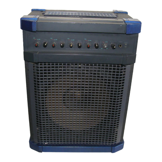
Page 7: Appearance
Specifications INPUT SPECIFICATIONS Actual For Use Input Level Load With Connector Input Nominal MAX. Before Clip Impedance Nominal PHONE JACK CHANNEL INPUT -30dB (24mV) 0dB (0.775V) RCA PIN JACK CH1~CH4 -60dB (0.78mV) -30dB (24mV) XLR-3-31 TYPE MIC CH1 -20dB (78mV) +10dB (2.45V) PHONE JACK AUX IN... - Page 8 Printed in Taiwan 133-02-838-2...