Table of Contents
Advertisement
Quick Links
Advertisement
Table of Contents

Related Manuals for Supero SUPERO X8QB6-F


Summary of Contents for Supero SUPERO X8QB6-F
- Page 1 X8QB6-F X8QBE-F USER’S MANUAL Revision 1.1b...
- Page 2 This product, including software and docu- mentation, is the property of Supermicro and/or its licensors, and is supplied only under a license. Any use or reproduction of this product is not allowed, except as expressly permitted by the terms of said license.
-
Page 3: About This Motherboard
Technology, combined with support of up to 32 CPU cores and 24MB L3 cache, the X8QB6-F/X8QBE-F motherboard substantially enhances system performance for HPC/Cluster/Database server platforms. Please refer to our Website (http://www. supermicro.com) for updates on supported processors. This product is intended to be installed and serviced by professional technicians. Manual Organization Chapter 1 provides quick installation instructions. -
Page 4: Conventions Used In The Manual
X8QB6-F /X8QBE-F Motherboard User’s Manual Conventions Used in the Manual Special attention should be given to the following symbols for proper installation and to prevent damage to the system or injury to yourself: Danger/Caution: Instructions to be strictly followed to prevent catastrophic system failure or to avoid bodily injury Warning: Important information given to ensure proper system installation or to prevent damage to the components... -
Page 5: Contacting Supermicro
Super Micro Computer, Inc. 980 Rock Ave. San Jose, CA 95131 U.S.A. Tel: +1 (408) 503-8000 Fax: +1 (408) 503-8008 Email: marketing@supermicro.com (General Information) support@supermicro.com (Technical Support) Website: www.supermicro.com Europe Address: Super Micro Computer B.V. Het Sterrenbeeld 28, 5215 ML... -
Page 6: Table Of Contents
X8QB6-F /X8QBE-F Motherboard User’s Manual Table of Contents Preface Chapter 1 Quick Installation Guide Installing the CPU ................... 1-1 Installing the CPU/Heatsink/ CPU Fans ............1-1 Installing the Memory Modules ............... 1-2 Installing the I/O Shield ................... 1-2 Installing the Motherboard ................1-3 Connecting the Power Supply................. - Page 7 Table of Contents Control Panel Connectors/I/O Ports...............3-11 Back Panel Connectors/I/O Ports ..............3-11 Back Panel I/O Port Locations and Defi nitions ..........3-11 Serial Ports ....................3-12 Video Connection ..................3-12 Universal Serial Bus (USB) ..............3-13 Ethernet Ports ..................3-14 Unit Identifi er Switch ................3-15 Front Control Panel ..................
- Page 8 X8QB6-F /X8QBE-F Motherboard User’s Manual SAS2 Enable (X8QB6-F only) ..............3-32 BMC Enable .................... 3-32 BMC Reset ....................3-33 Onboard LED Indicators ................3-34 GLAN LEDs ....................3-34 IPMI Dedicated LAN LEDs ............... 3-34 Rear UID LED ..................3-35 BMC Heartbeat LED ................3-35 Onboard Power LED ................
-
Page 9: Chapter 1 Quick Installation Guide
Chapter 1: Quick Installation Guide Chapter 1 Quick Installation Guide Installing the CPU CPU Key A. Press the socket clip down to unlock B. Align the CPU key with the socket it. Gently lift the socket clip to open the key. -
Page 10: Installing The Memory Modules
X8QB6-F/X8QBE-F Motherboard User’s Manual Installing the Memory Modules A. Press the release tabs on the both B. Use two thumbs to press both ends of the DIMM socket outwards to notches of the module straight down unlock it. into the DIMM socket. Align the key on the DIMM module C. -
Page 11: Installing The Motherboard
Chapter 1: Quick Installation Guide Installing the Motherboard X8QBE-F Rev. 1.11 Connecting the Power Supply X8QBE-F Rev. 1.11 Note: Please connect the 24-pin power connector and three of the four 8-pin power connectors to the power supply to provide adequate power supply to your system. -
Page 12: Installing Internal Peripherals
X8QB6-F/X8QBE-F Motherboard User’s Manual Installing Internal Peripherals Add-on Cards SATA/SAS2 Drives Installing External Peripherals IPMI LAN Serial Port VGA Port USB 0/1 LAN 1/2 Ports (COM1) Switch... -
Page 13: Chapter 2 Overview
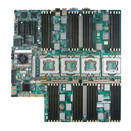
Checklist Congratulations on purchasing your computer motherboard from an acknowledged leader in the industry. Supermicro boards are designed with the utmost attention to detail to provide you with the highest standards in quality and performance. Please check that the following items have all been included with your motherboard. - Page 14 X8QB6-F/X8QBE-F Motherboard User’s Manual Motherboard Image Note: All graphics shown in this manual were based upon the latest PCB Revision available at the time of publishing of the manual. The motherboard you've received may or may not look exactly the same as the graphics shown in this manual.
- Page 15 3-26 in Chapter 3 for more details. Note 2: For the latest CPU/Memory updates, please refer to our website at http://www.supermicro.com/products/motherboard/ for details. Note 3: To ensure adequate power supply to the motherboard for proper system operation, please use a power supply that supports the following specifi...
-
Page 16: X8Qb6-F/X8Qbe-F Quick Reference
X8QB6-F/X8QBE-F Motherboard User’s Manual X8QB6-F/X8QBE-F Quick Reference USB0/1 LAN1 COM1 LED26 FAN10 UID_LED (LOWER) BMC_HB JUIDB1 UID_SWITCH FAN8 FAN9 Intel 82576 Winbond BMCRST BMC CTRL LAN CTRL IPMI_LAN LAN2 (UPPER) JBT1 Intel ICH 10R BIOS Intel IOH 7500 CPU3 CPU1 CPU2 CPU4 SAS0~3... - Page 17 Chapter 2: Overview X8QB6-F/X8QBE-F Jumpers Jumper Description Default Setting JBT1 Clear CMOS See Chapter 3 JPB1 BMC Enabled Pins 1-2 (Enabled) JPG1 VGA Enabled Pins 1-2 (Enabled) JPL1 GLAN1/GLAN2 Enable Pins 1-2 (Enabled) JPRST1 BMC Reset Off (Normal) JPS1 (X8QB6-F only) SAS2 Enabled Pins 1-2 (Enabled) JPT1...
- Page 18 Note 1: To enable extended battery backup support for onboard SAS, please purchase a LSI 2108 SAS Battery Accessory kit from Supermicro. Refer to Page 3-26 in Chapter 3 for more details. Note 2: To ensure adequate power supply to the motherboard for proper system operation, please use a power supply that supports the following specifi...
-
Page 19: Motherboard Features
Chapter 2: Overview Motherboard Features • ® Four Intel 7500 Series (Socket LS-LGA 1567) pro- cessors; each processor supports four full-width Intel QuickPath Interconnect (QPI) links (with support of up to 25.6 GT/s per QPI link and with Data Transfer Rate of up to 6.4 GT/s per direction) •... - Page 20 X8QB6-F/X8QBE-F Motherboard User’s Manual I/O Devices SATA Connections • SATA Ports Six (6) • R A I D ( W i n - RAID 0, 1, 5, 10 dows) • RAID (Linux) RAID 0, 1, 10 SAS2 Connections • LSI SAS2 2108 Controller •...
- Page 21 SuperoDoctor III, Watch Dog, NMI • Chassis Intrusion Header and Detection • Dimensions 16.79" (L) x 16.00" (W) (426.46 mm x 406.40 mm) Note: For IPMI Confi guration Instructions, please refer to the Embedded IPMI Confi guration User's Guide available @ http://www.supermicro.com/ support/manuals/.
-
Page 22: System Block Diagram
X8QB6-F/X8QBE-F Motherboard User’s Manual 6.4GT/s 6.4GT/s FBD0 FBD0 SMI 6.4GT/s SMI 6.4GT/s FBD1 FBD1 SMI 6.4GT/s SMI 6.4GT/s FBD2 FBD2 SMI 6.4GT/s FBD3 SMI 6.4GT/s FBD3 6.4GT/s 6.4GT/s FBD0 FBD0 SMI 6.4GT/s SMI 6.4GT/s FBD1 QPI 6.4GT/s FBD1 SMI 6.4GT/s FBD2 SMI 6.4GT/s FBD2... -
Page 23: Chipset Overview
Chapter 2: Overview Chipset Overview Built upon the functionality and the capability of the Intel 7500 platform, the X8QB6-F/X8QBE-F motherboard provides the performance and support for quad_processor-based HPC/Cluster/Database servers. The 7500 platform con- sists of the 7500 Series Socket-LS (LGA 1567) processor, the 7500 (IOH), and the ICH10R (South Bridge). -
Page 24: Special Features
X8QB6-F/X8QBE-F Motherboard User’s Manual Special Features Recovery from AC Power Loss The Basic I/O System (BIOS) provides a setting for you to determine how the sys- tem will respond when AC power is lost and then restored to the system. You can choose for the system to remain powered off (in which case you must press the power switch to turn it back on), or for it to automatically return to the power- on state. -
Page 25: Acpi Features
Chapter 2: Overview System Resource Alert This feature is available when used with Supero Doctor III in the Windows OS environment or used with Supero Doctor II in Linux. Supero Doctor is used to notify the user of certain system events. For example, you can confi gure Supero Doctor to provide you with warnings when the system temperature, CPU temperatures, voltages and fan speeds go beyond a predefi... -
Page 26: Super I/O
X8QB6-F/X8QBE-F Motherboard User’s Manual connectors. Be sure to connect these power supply connectors to the 24-pin (JPWR3) and three of the four 8-pin power connectors (JPWR1, JPWR2, JPWR4, or JPWR5) on the motherboard. Failure to do so will void the manufacturer warranty on your power supply and motherboard. It is strongly recommended that you use a high quality power supply that meets ATX power supply Specifi... -
Page 27: Chapter 3 Installation
Chapter 3: Installation Chapter 3 Installation Static-Sensitive Devices Electrostatic Discharge (ESD) can damage electronic com ponents. To avoid dam- aging your system board, it is important to handle it very carefully. The following measures are generally suffi cient to protect your equipment from ESD. Precautions •... -
Page 28: Processor And Heatsink Installation
X8QB6-F/X8QBE-F Motherboard User's Manual Processor and Heatsink Installation When handling the processor package, avoid placing direct pressure on the label area of the fan. Notes: Always connect the power cord last, and always remove it before adding, removing or changing any hardware components. Make sure that you install the processor into the CPU socket before you install the CPU heatsink. - Page 29 Chapter 3: Installation After removing the plastic cap, using your thumb and the index fi nger, hold the CPU at the north and south center edges. Align the CPU key, which is a semi-circle cutout, against the socket key, which is the notch below the gold color dot on the side of the socket. CPU Key CPU Pin 1 Align Pin 1 on the CPU against Pin 1 on the CPU socket.
-
Page 30: Installing A Passive Cpu Heatsink
X8QB6-F/X8QBE-F Motherboard User's Manual Installing a Passive CPU Heatsink Apply the proper amount of thermal grease (with thickness of up to 0.13 mm) to the heatsink. Place the heatsink on top of the CPU so that the two mounting holes on the heatsink are aligned with those on the retention mechanism. -
Page 31: Removing The Passive Heatsink
Chapter 3: Installation Removing the Passive Heatsink Warning: We do not recommend that the CPU or the heatsink be re- moved. However, if you do need to remove the heatsink, please follow the instructions below to uninstall the heatsink to avoid damaging the CPU or other components. -
Page 32: Installing And Removing The Memory Modules
X8QB6-F/X8QBE-F Motherboard User's Manual Installing and Removing the Memory Modules Note: Check Supermicro's website for recommended memory modules. CAUTION Exercise extreme care when installing or removing DIMM modules to prevent any possible damage. Installing & Removing DIMMs Insert the desired number of DIMMs into the memory slots, starting with P1- DIMM #1A. - Page 33 DDR3 1066 MHz memory in 32 DIMM slots. These RDIMMs run at 800/978/1066 via a memory buffer. For the latest memory updates, please refer to our website a at http://www.supermicro.com/products/motherboard. Processor & Memory Module Population Confi guration For memory to work properly, follow the tables below for memory installation.
- Page 34 X8QB6-F/X8QBE-F Motherboard User's Manual 4 CPUs & CPU1/CPU2/CPU3/CPU4 8 DIMMs P1-1A/P1-3A, P2-1A/P2-3A,P3-1A/P3-3A + P4-1A/P4-3A 4 CPUs & CPU1/CPU2/CPU3/CPU4 10 DIMMs P1-1A/P1-3A/P1-5A/P1-7A, P2-1A/P2-3A,P3-1A/P3-3A + P4-1A/P4-3A 4 CPUs & CPU1/CPU2/CPU3/CPU4 12 DIMMs P1-1A/P1-3A/P1-5A/P1-7A, P2-1A/P2-3A/P2-5A/P2-7A, P3-1A/P3-3A, P4-1A/P4-3A 4 CPUs & CPU1/CPU2/CPU3/CPU4 14 DIMMs P1-1A/P1-3A/P1-5A/P1-7A, P2-1A/P2-3A/P2-5A/P2-7A,P3-1A/P3-3A/P3-5A/P3-7A, P4-1A/P4-3A 4 CPUs &...
-
Page 35: Motherboard Installation
Chapter 3: Installation Motherboard Installation All motherboards have standard mounting holes to fi t different types of chassis. Make sure that the locations of all the mounting holes for both motherboard and chassis match. Although a chassis may have both plastic and metal mounting fas- teners, metal ones are highly recommended because they ground the motherboard to the chassis. -
Page 36: Installing The Motherboard
X8QB6-F/X8QBE-F Motherboard User's Manual Installing the Motherboard Install the I/O shield into the chassis. Locate the mounting holes on the motherboard. Locate the matching mounting holes on the chassis. Align the mounting holes on the motherboard against the mounting holes on the chassis. Install standoffs in the chassis as needed. -
Page 37: Control Panel Connectors/I/O Ports
Chapter 3: Installation Control Panel Connectors/I/O Ports The I/O ports are color coded in conformance with the PC 99 specifi cation. See the picture below for the colors and locations of the various I/O ports. Back Panel Connectors/I/O Ports LED26 FAN10 LAN1 USB0/1... -
Page 38: Serial Ports
X8QB6-F/X8QBE-F Motherboard User's Manual Serial Ports Serial COM) Ports Pin Defi nitions Two COM connections (COM1 & Pin # Defi nition Pin # Defi nition COM2) are located on the motherboard. COM1 is located on the Backplane I/O panel. COM2, located close to the 7500 IOH, provides front accessible serial support. -
Page 39: Universal Serial Bus (Usb)
Chapter 3: Installation Universal Serial Bus (USB) FP USB (2/3, 5) Backplane USB Pin Defi nitions (0/1) Two Universal Serial Bus ports (USB Pin Defi nitions USB 2 USB 3/5 0/1) are located on the I/O back panel. Pin # Defi nition Pin # Defi... -
Page 40: Ethernet Ports
X8QB6-F/X8QBE-F Motherboard User's Manual Ethernet Ports LAN Ports Pin Defi nition Two Ethernet ports (LAN1/LAN2) are Pin# Defi nition located on the I/O backplane on the P2V5SB SGND motherboard. In addition, an IPMI_ TD0+ Act LED Dedicated LAN is located above USB TD0- P3V3SB 0/1 ports on the backplane to provide... -
Page 41: Unit Identifi Er Switch
Chapter 3: Installation Unit Identifi er Switch UID Switch A Unit Identifi er (UID) Switch and two LED Pin# Defi nition Indicators are located on the motherboard. Ground The UID Switch is located next to the LAN Ground ports on the backplane. The Rear UID LED Button In (LED26) is located next to the UID Switch. -
Page 42: Front Control Panel
These connectors are designed specifi cally for use with Supermicro's server chassis. See the fi gure below for the descriptions of the various control panel buttons and LED indicators. Refer to the following section for descriptions and pin defi... -
Page 43: Front Control Panel Pin Defi Nitions
Chapter 3: Installation Front Control Panel Pin Defi nitions NMI Button NMI Button Pin Defi nitions (JF1) The non-maskable interrupt button Pin# Defi nition header is located on pins 19 and 20 Control of JF1. Refer to the table on the right Ground for pin defi... -
Page 44: Hdd Led
X8QB6-F/X8QBE-F Motherboard User's Manual HDD LED HDD LED Pin Defi nitions (JF1) The HDD LED connection is located Pin# Defi nition on pins 13 and 14 of JF1. Attach a 3.3V Standby cable here to indicate HDD activ- HD Active ity. -
Page 45: Overheat (Oh)/Fan Fail/Pwr Fail/Uid Led
Chapter 3: Installation Overheat (OH)/Fan Fail/PWR Fail/ OH/Fan Fail/PWR Fail/UID LED Pin Defi nitions (JF1) UID LED Pin# Defi nition Connect an LED cable to OH/Fan Fail/ Red+ (Blue LED Cathode) Front UID LED connection on pins 7 Blue+ (OH/Fan Fail/PWR Fail/ and 8 of JF1 to provide advanced UID LED) warnings of chassis overheat or fan... -
Page 46: Reset Button
X8QB6-F/X8QBE-F Motherboard User's Manual Reset Button Reset Button Pin Defi nitions (JF1) The Reset Button connection is located Pin# Defi nition on pins 3 and 4 of JF1. Attach it to a Reset hardware reset switch on the computer Ground case. -
Page 47: Connecting Cables
Chapter 3: Installation Connecting Cables ATX Power 24-pin Connector Pin Defi nitions Pin# Defi nition Pin # Defi nition Power Connectors +3.3V +3.3V -12V +3.3V 2 4 - p i n m a i n p o w e r s u p p l y connector(JPWR3) and four 8-pin CPU PS_ON... -
Page 48: Fan Headers
X8QB6-F/X8QBE-F Motherboard User's Manual Fan Headers Fan Header Pin Defi nitions This motherboard has ten system/CPU Pin# Defi nition fan headers (Fan 1 to Fan10) on the Ground motherboard. (Fan 11: reserved) All +12V these 4-pin fans headers are backward Tachometer compatible with the traditional 3-pin fans. -
Page 49: Internal Speaker
Chapter 3: Installation Internal Speaker Internal Buzzer (SP1) Pin Defi nition The Internal Speaker, located at SP1, Pin# Defi nitions can be used to provide audible indica- Pin 1 Pos. (+) Beep In tions for various beep codes. See the Pin 2 Neg. -
Page 50: Tpm Header/Port 80
X8QB6-F/X8QBE-F Motherboard User's Manual TPM Header/Port 80 TPM/Port 80 Header Pin Defi nitions A Trusted Platform Module/Port 80 Pin # Defi nition Pin # Defi nition header is located at LPCI to provide LCLK TPM support and Port 80 connection. LFRAME# <(KEY)>... -
Page 51: Power Smb (I C) Connector
Chapter 3: Installation Power SMB (I C) Connector PWR SMB Pin Defi nitions Power System Management Bus (I Pin# Defi nition Connector (JPI C) monitors power Clock supply, fan and system temperatures. Data See the table on the right for pin PWR Fail defi... -
Page 52: T-Sgpio 1/2 Headers
X8QB6-F/X8QBE-F Motherboard User's Manual T-SGPIO 1/2 Headers T-SGPIO Pin Defi nitions Two SGPIO (Serial-Link General Pin# Defi nition Defi nition Purpose Input/Output) headers are located on the motherboard. These Ground Data headers support Serial_Link interface Load Ground for onboard SATA connections. See Clock the table on the right for pin defi... -
Page 53: Bbu Header (Optional For The X8Qb6-F Only)
'power shortage.' To enable extended battery support, an optional battery backup accessory kit is required. Please contact our sales at Supermicro to purchase an LSI 2108 SAS Battery Backup Accessory kit. Also, contact our tech support for installation instructions and possible component updates. -
Page 54: Unit Identifi Cation Switch/Led
X8QB6-F/X8QBE-F Motherboard User's Manual Unit Identifi cation Switch/LED UID Switch (UID) Pin Defi nitions A Unit Identifi er switch (UID) and a rear UID Pin# Defi nition LED indicator (LED26) are located next to Ground Fan10 on the back of the chassis. When Ground the user pushes the rear UID switch, the Button In... -
Page 55: Jumper Settings
Chapter 3: Installation Jumper Settings Explanation of Jumpers Connector Pins To modify the operation of the mother- board, jumpers can be used to choose between optional settings. Jumpers cre- Jumper ate shorts between two pins to change the function of the connector. Pin 1 is identifi... -
Page 56: Cmos Clear
X8QB6-F/X8QBE-F Motherboard User's Manual CMOS Clear JBT1 is used to clear CMOS. Instead of pins, this "jumper" consists of contact pads to prevent accidental clearing of CMOS. To clear CMOS, use a metal object such as a small screwdriver to touch both pads at the same time to short the connection. Always remove the AC power cord from the system before clearing CMOS. -
Page 57: Vga Enable
See the table on the right for jumper settings. The default setting is enabled. Note: For more information on IPMI confi guration, please refer to the WPCM 450 IPMI BMC User's Guide posted on our website @ http://www. supermicro.com. LAN1 USB0/1 COM1 LED26... -
Page 58: X8Qb6-F/X8Qbe-F Motherboard User's Manual
X8QB6-F/X8QBE-F Motherboard User's Manual SAS2 Enable (X8QB6-F only) SAS2 Enable Close pins 1-2 of JPS1 to enable SAS2 Jumper Settings (Serial_Attached_SCSI) support on the Jumper Setting Defi nition X8QB6-F motherboard. See the table on Enabled (Default) the right for jumper settings. The default Disabled setting is enabled. -
Page 59: Bmc Reset
Chapter 3: Installation BMC Reset BMC Reset Jumper Settings Use Jumper JPRST1 to reset the BMC Jumper Setting Defi nition settings on the motherboard. See the Closed BMC Reset table on the right for jumper settings. Closed Normal (Default) USB0/1 LED26 LAN1 COM1... -
Page 60: Onboard Led Indicators
X8QB6-F/X8QBE-F Motherboard User's Manual A c t i v i t y L i n k Onboard LED Indicators GLAN LEDs There are two GLAN ports on the moth- Rear View (when facing the erboard. Each Gigabit Ethernet LAN port rear side of the chassis) has two LEDs. -
Page 61: Rear Uid Led
Chapter 3: Installation Rear UID LED UID LED LED Status The rear UID LED is located at LED26 Color/State OS Status on the backplane. This LED is used in Blue: On Windows OS Unit Identifi ed conjunction with the rear UID switch to Blue: Linux OS Unit Identifi... -
Page 62: Onboard Power Led
X8QB6-F/X8QBE-F Motherboard User's Manual Onboard Power LED Onboard PWR LED Indicator LED Status An Onboard Power LED is located at LED LED Color Defi nition 8 on the motherboard. When this LED is System Off (PWR cable not connected) on, the system is on. Be sure to turn off the Green System On system and unplug the power cord before... -
Page 63: Serial Ata Connections
LSI 2108 Controller. See the table on the right for pin defi nitions. Note: For more information on SATA HostRAID confi guration, please refer to the Intel SATA HostRAID User's Guide posted on our website @ http:// www.supermicro.com.. USB0/1 LED26 LAN1... - Page 64 X8QB6-F/X8QBE-F Motherboard User's Manual Notes 3-38...
-
Page 65: Chapter 4 Troubleshooting
Chapter 4: Troubleshooting Chapter 4 Troubleshooting Troubleshooting Procedures Use the following procedures to troubleshoot your system. If you have followed all of the procedures below and still need assistance, refer to the ‘Technical Support Procedures’ and/or ‘Returning Merchandise for Service’ section(s) in this chapter. Note: Always disconnect the power cord before adding, changing or installing any hardware components. -
Page 66: System Boot Failure
X8QB6-F/X8QBE-F Motherboard User's Manual No Video If the power is on, but you have no video, remove all the add-on cards and cables. Use the speaker to determine if any beep codes exist. Refer to Appendix A for details on beep codes. System Boot Failure If the system does not display POST or does not respond after the power is turned on, check the following:... -
Page 67: Memory Errors
Memory support: Make sure that the memory modules are supported by test- ing the modules using memtest86 or a similar utility. Note: Refer to the product page on our website http:\\www.supermicro. com for memory and CPU support and updates. HDD support: Make sure that all hard disk drives (HDDs) work properly. Re- place the bad HDDs with good ones. -
Page 68: Technical Support Procedures
You can also install the component in question in another system. If the new system works, the component is good and the old system has problems. Technical Support Procedures Before contacting Technical Support, please take the following steps. Also, please note that as a motherboard manufacturer, Supermicro also sells motherboards... -
Page 69: Frequently Asked Questions
It is recommended that you do not upgrade your BIOS if you are not experiencing any problems with your system. Updated BIOS fi les are located on our website at http://www.supermicro.com. Please check our BIOS warning message and the information on how to update your BIOS on our website. Select your motherboard... -
Page 70: Returning Merchandise For Service
Note : The SPI BIOS chip used on this motherboard cannot be removed. Send your motherboard back to our RMA Department at Supermicro for repair. For BIOS Recovery instructions, please refer to the AMI BIOS Recovery Instructions posted at http://www.supermicro.com. -
Page 71: Chapter 5 Bios
When an option is selected in the left frame, it is highlighted in white. Often a text message will accompany it. (Note: AMI BIOS has default text messages built in. Supermicro retains the option to include, omit, or change any of these text messages.) The AMI BIOS Setup Utility uses a key-based navigation system called "hot keys."... -
Page 72: Starting The Setup Utility
Warning! Do not upgrade the BIOS unless your system has a BIOS-related issue. Flashing the wrong BIOS can cause irreparable damage to the system. In no event shall Supermicro be liable for direct, indirect, special, incidental, or consequential damages arising from a BIOS update. If you have to update the BIOS, do not shut down or reset the system while the BIOS is updating to avoid possible boot failure. - Page 73 <Enter>. Press the <Tab> key to move between fi elds. The date must be entered in Day MM/DD/YY format. The time is entered in HH:MM:SS format. (Note: The time is in the 24-hour format. For example, 5:30 P.M. appears as 17:30:00.) Supermicro X8QB6/E • BIOS Version : This item displays the BIOS vision used in your system.
-
Page 74: Advanced Setup Confi Gurations
X8QB6-F/X8QBE-F Motherboard User’s Manual Advanced Setup Confi gurations Use the arrow keys to select Advanced Settings and press <Enter> to access the submenu items. Warning: Be sure to select the correct setting for each item in this section. A wrong setting selected may cause the system to malfunction. Boot Features Quick Boot If enabled, this feature will skip certain tests during POST to reduce the time needed... -
Page 75: Processor And Clock Options
Chapter 5: AMI BIOS PS/2 Mouse Support Select Enabled to enable PS/2 Mouse support. Select Auto to enable the onboard PS/2 mouse when a PS/2 mouse is detected. The options are Enable, Disabled, and Auto. Wait For 'F1' If Error This forces the system to wait until the 'F1' key is pressed when an error occurs. - Page 76 X8QB6-F/X8QBE-F Motherboard User’s Manual Sever Class Use this item to identify the server class for your system so that the prefectcher settings listed below can be correctly confi gured. The options are Enterprise, HPC (High Performance Cluster) and Custom (for customized servers). Hardware Prefetcher (Available when supported by the CPU) If enabled, the hardware prefetcher will prefetch streams of data and instructions from the main memory to the L2 cache to improve CPU performance.
- Page 77 Chapter 5: AMI BIOS CPU Multi-Core Enable/Disable (Available when supported by the CPU) Select Enabled to enable multi-core CPU support to enhance CPU performance. The options are Disabled and Enabled. A20M When the A20M# pin is enabled, it will force address bit 20 to zero (to be masked) to emulate the address wraparound for the real-address mode at 1 MB.
-
Page 78: Advanced Chipset Control
X8QB6-F/X8QBE-F Motherboard User’s Manual ACPI T State When this feature is enabled, CPU Throttling state will be reported in the ACPI (Advanced Confi guration and Power Interface) protocol. The options are Enabled and Disabled. Advanced Chipset Control The items included in the Advanced Settings submenu are listed below. CPU Bridge Confi... - Page 79 Chapter 5: AMI BIOS QPI (Quick Path Interconnect) Links Speed Use this feature to set data transfer speed for QPI Link connections. The options are Slow and Fast. QPI Frequency Select (Available if the item - QPI Link Speed is set to Fast) This feature is used to set desired QPI frequency.
- Page 80 X8QB6-F/X8QBE-F Motherboard User’s Manual • Inter-Socket Mirrored S0 (Socket 0) to S2 (Socket 2) and S1 (Socket 1) to S3 (Socket 3), • Inter-Socket Mirrored S0 (Socket 0) to S3 (Socket 3) and S1 (Socket 1) to S2 (Socket 2). Spare Enable Select Enabled to enable spare support for all sockets, creating a spare drive for each socket.
- Page 81 Chapter 5: AMI BIOS Scheduler Policy Use this feature to confi gure Scheduler_Policy settings. The scheduler is used to translate memory read/write commands into memory sub-commands for easy execution. Select Static Trade_Off to balance read/write priority. Select Static Read_Priority to optimize read latency and bandwidth. Select Static Write_Pri- ority to optimize write bandwidth to expedite command writing and execution.
- Page 82 X8QB6-F/X8QBE-F Motherboard User’s Manual Active State Power Management Select Enabled to use the power management for signal transactions between the PCI Express L0 and L1 Links. Select Enabled to confi gure PCI-Exp. L0 and L1 Link power states. The options are Disabled and Enabled. Extended Synch Select Enabled to generate extended synchronization patterns.
- Page 83 Chapter 5: AMI BIOS SMBUS Controller Select Enabled to enable the System_Management Bus Controller. The settings are Enabled and Disabled. SLP_S4# Min. Assertion Width This feature allows the user to set the minimum SLP_S4# Assertion Width to make sure that DRAMs have safe power cycles. The settings are 4 to 5 seconds, 3 to 4 Seconds, 2 to 3 Seconds, and 1 to 2 Seconds.
- Page 84 X8QB6-F/X8QBE-F Motherboard User’s Manual SATA#1 Confi guration If Compatible is selected, it sets SATA#1 to the legacy_compatible mode. Select- ing Enhanced sets SATA#1 to the native SATA mode. The options are Disabled, Compatible and Enhanced. Confi gure SATA#1 as (Not available when SATA#1 Confi guration is disabled) Use this feature to select the drive type for SATA#1.
- Page 85 Chapter 5: AMI BIOS Block (Multi-Sector Transfer) Block Mode boosts the IDE drive performance by increasing the amount of data transferred. Only 512 bytes of data can be transferred per interrupt if Block Mode is not used. Block Mode supports transfers of up to 64 KB per interrupt. Select Disabled to allow data to be transferred from and to a device one sector at a time.
- Page 86 X8QB6-F/X8QBE-F Motherboard User’s Manual Select MWDMA0 to allow BIOS to use Multi-Word DMA mode 0. It has a data transfer rate of 4.2 MB/s. Select MWDMA1 to allow BIOS to use Multi-Word DMA mode 1. It has a data transfer rate of 13.3 MB/s. Select MWDMA2 to allow BIOS to use Multi-Word DMA mode 2.
- Page 87 Chapter 5: AMI BIOS PCI/PnP Confi guration Clear NVRAM Select Yes to clear Non-Volatile Random Access (Flash) Memory (NVRAM) during system boot. The options are No and Yes. Plug & Play OS Select Yes to allow the OS to confi gure Plug & Play devices. (This is not required for system boot if your system has an OS that supports Plug &...
- Page 88 X8QB6-F/X8QBE-F Motherboard User’s Manual LAN1 Option ROM/LAN2 Option ROM Select Enabled to enable the onboard LAN1/LAN2 Option ROMs to boot the com- puter using a network interface. The options are Enabled and Disabled. Super IO Device Confi guration Serial Port1 Address/IRQ, Serial Port2 Address/IRQ This option specifi...
- Page 89 Chapter 5: AMI BIOS Hot-Plug USB FDD Support When this item is set to Enabled, a dummy Floppy Device Drive will be created as a Hot-Plug Floppy device in the system. When this item is set to Auto, a dummy fl...
- Page 90 X8QB6-F/X8QBE-F Motherboard User’s Manual Energy Lake Feature Select Enabled to use Intel Energy Lake technology to enhance power effi ciency. The options are Disabled and Enabled. APIC ACPI SCI IRQ When this item is set to Enabled, APIC ACPI SCI IRQ is supported by the system. The options are Enabled and Disabled.
-
Page 91: Hardware Health Event Monitoring
Chapter 5: AMI BIOS Hardware Health Event Monitoring This feature is used to monitor system health and review the status of each item as displayed. CPU Overheat Alarm This option allows the user to select the CPU Overheat Alarm setting which de- termines when the CPU OH alarm will be activated to provide warning of possible CPU overheat. - Page 92 ‘Temperature Tolerance’ is, and not the other way around. This results in better CPU thermal management. Supermicro has leveraged this feature by assigning a temperature status to certain thermal conditions in the processor (Low, Medium and High). This makes it easier for the user to understand the CPU’s temperature status, rather than by just simply...
-
Page 93: View Bmc System Event Log
Chapter 5: AMI BIOS Fan Speed Control Modes This feature allows the user to decide how the system controls the speeds of the onboard fans. The CPU temperature and the fan speed are correlative. When the CPU on-die temperature increases, the fan speed will also increase for effective system cooling. - Page 94 X8QB6-F/X8QBE-F Motherboard User’s Manual • Event Timestamp • Generator ID • Event Message Format Ver. • Event Sensor Type • Event Sensor Number • Event Dir Type • Event Data. Clear BMC System Event Log Clear BMC System Log now Select OK and press <Enter>...
- Page 95 Chapter 5: AMI BIOS a "request and grant" basis. Upon timeout (or lease expiration), the IP address assigned to the client can be reassigned to a new client. Select Static (Static Allocation) to allow the host server to allocate an IP address based on a table containing MAC Address/IP Address pairs that are manually entered (probably by a network administrator).
- Page 96 X8QB6-F/X8QBE-F Motherboard User’s Manual Current Subnet Mask in BMC The BIOS will automatically enter the current subnet mask in BMC for this machine; however it may be overwritten. The value of each three-digit number separated by dots should not exceed 255. ...
- Page 97 Chapter 5: AMI BIOS Redirection After BIOS POST Select Disabled to turn off Console Redirection after Power-On Self-Test (POST). Select Always to keep Console Redirection active all the time after POST. (Note: This setting may not be supported by some operating systems.) Select Boot Loader to keep Console Redirection active during POST and Boot Loader.
- Page 98 X8QB6-F/X8QBE-F Motherboard User’s Manual Execute TPM Command (Available when TCG/TPM Support = 'Yes') Select Enabled to execute TPM commands you've selected. Select Don't Change to keep the current TPM commands without making any changes. Select Dis- abled to abandon the changes you have made on TPM commands. The options are Enabled, Disabled and Don't Change.
-
Page 99: Boot Confi Guration
Chapter 5: AMI BIOS Boot Confi guration Use this feature to confi gure boot settings. Boot Device Priority This feature allows the user to specify the sequence of priority for the Boot Device. The settings are 1st boot device, 2nd boot device, 3rd boot device, 4th boot device, 5th boot device and Disabled. -
Page 100: Security Settings
X8QB6-F/X8QBE-F Motherboard User’s Manual Security Settings The AMI BIOS provides a Supervisor and a User password. If you use both pass- words, the Supervisor password must be set fi rst. Supervisor Password This item indicates if a Supervisor password has been entered for the system. "Not Installed"... -
Page 101: Exit Options
Chapter 5: AMI BIOS Password Check Select Setup for the system to check for a password at Setup. Select Always for the system to check for a password at bootup. The options are Setup and Always. Boot Sector Virus Protection If this item is enabled, AMI BIOS displays a warning if any program (or virus) issues a Disk Format command or attempts to write to the boot sector of the hard disk drive. - Page 102 X8QB6-F/X8QBE-F Motherboard User’s Manual Load Optimal Defaults To set this feature, select Load Optimal Defaults from the Exit menu and press <Enter>. Then, select OK to allow the AMI BIOS to automatically load Optimal De- faults to the BIOS Settings. The Optimal settings are designed for maximum system performance but may not work best for all computer applications.
-
Page 103: Appendix A Bios Error Beep Codes
Appendix A: BIOS POST Error Codes Appendix A BIOS Error Beep Codes During the POST (Power-On Self-Test) routines, which are performed at each system boot, errors may occur. Non-fatal errors are those which, in most cases, allow the system to continue to boot. - Page 104 X8QB6-F/X8QBE-F User's Manual Notes...
-
Page 105: Appendix B Software Installation Instructions
To install these programs, click the icons to the right of these items. Note: To install the Windows OS, please refer to the instructions posted on our Website at http://www.supermicro.com/support/manuals/. Driver/Tool Installation Display Screen Note 1. Click the icons showing a hand writing on the paper to view the readme fi... -
Page 106: B-2 Confi Guring Supero Doctor Iii
X8QB6-F/X8QBE-F Motherboard User's Manual B-2 Confi guring Supero Doctor III The Supero Doctor III program is a web-based management tool that supports remote management capability. It includes Remote and Local Management tools. The local management is called the SD III Client. The Supero Doctor III program included on the CDROM that came with your motherboard allows you to monitor the environment and operations of your system. - Page 107 Supero Doctor III Interface Display Screen-II (Remote Control) Note: SD III Software Revision 1.0 can be downloaded from our web- site at: ftp://ftp.Supermicro.com/utility/Supero_Doctor_III/. You can also download SDIII User's Guide at: http://www.supermicro.com/PRODUCT/ Manuals/SDIII/UserGuide.pdf. For Linux, we will still recommend that you...
- Page 108 X8QB6-F/X8QBE-F Motherboard User's Manual Notes...
- Page 109 (Disclaimer Continued) The products sold by Supermicro are not intended for and will not be used in life support systems, medical equipment, nuclear facilities or systems, aircraft, aircraft devices, aircraft/emergency communication devices or other critical systems whose failure to perform be reasonably expected to result in signifi cant injury or loss of life or catastrophic property damage.