
Related Manuals for Supero Supero X8DTL-3


Summary of Contents for Supero Supero X8DTL-3
- Page 1 X8DTL-3 X8DTL-i X8DTL-3F X8DTL-iF USER’S MANUAL Revision 1.2a...
- Page 2 This product, including software and docu- mentation, is the property of Supermicro and/or its licensors, and is supplied only under a license. Any use or reproduction of this product is not allowed, except as expressly permitted by the terms of said license.
-
Page 3: About This Manual
HCP/Cluster systems and intensive applications. Please refer to our web site (http://www.supermicro.com/products/) for updates on processor and memory support. This product is intended to be installed and serviced by professional technicians. - Page 4 X8DTL-3/X8DTL-i/X8DTL-3F/X8DTL-iF User's Manual Danger/Caution: Instructions to be strictly followed to prevent catastrophic system failure or to avoid bodily injury. Warning: Important information given to ensure proper system installation or to prevent damage to the components. Note: Additional Information given to differentiate various models or to ensure correct system setup.
-
Page 5: Contacting Supermicro
Super Micro Computer, Inc. 980 Rock Ave. San Jose, CA 95131 U.S.A. Tel: +1 (408) 503-8000 Fax: +1 (408) 503-8008 Email: marketing@supermicro.com (General Information) support@supermicro.com (Technical Support) Web Site: www.supermicro.com Europe Address: Super Micro Computer B.V. Het Sterrenbeeld 28, 5215 ML... -
Page 6: Table Of Contents
X8DTL-3/X8DTL-i/X8DTL-3F/X8DTL-iF User's Manual Table of Contents Preface Chapter 1 Introduction Overview ......................1-1 Chipset Overview .................... 1-9 Special Features ................... 1-10 PC Health Monitoring ..................1-10 ACPI Features ....................1-11 Power Supply ....................1-12 Super I/O ....................... 1-12 Overview of the Nuvoton WPCM450R Controller (For X8DTL-3F/X8DTL-iF Only) ........................ - Page 7 Table of Contents Internal Speaker ..................2-23 Power LED/Speaker ................. 2-23 Wake-On-LAN ..................2-24 Overheat LED/Fan Fail (JOH1) ..............2-24 T-SGPIO 1/2 & 3-SGPIO 1/2 Headers ............. 2-25 I-Button (For X8DTL-3/3F only)..............2-25 Power SMB (I C) Connector ..............2-26 IPMB ......................
- Page 8 X8DTL-3/X8DTL-i/X8DTL-3F/X8DTL-iF User's Manual Returning Merchandise for Service..............3-4 Chapter 4 BIOS Introduction ...................... 4-1 Starting BIOS Setup Utility ................4-1 How To Change the Confi guration Data ............4-1 Starting the Setup Utility ................. 4-2 Main Setup ...................... 4-2 Advanced Setup Confi gurations..............4-4 Power Confi...
-
Page 9: Chapter 1 Introduction
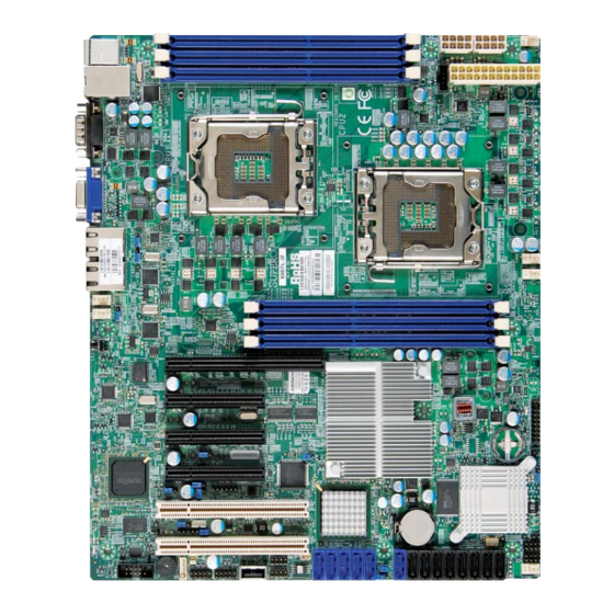
Checklist Congratulations on purchasing your computer motherboard from an acknowledged leader in the industry. Supermicro boards are designed with the utmost attention to detail to provide the highest standards in quality and performance. Check that the following items have all been included with your motherboard. If anything listed here is damaged or missing, contact your retailer. - Page 10 X8DTL-3/X8DTL-i/X8DTL-3F/X8DTL-iF User's Manual X8DTL-3/X8DTL-i/X8DTL-3F/X8DTL-iF Image Note: The drawings and pictures shown in this manual were based on the latest PCB Revision available at the time of publishing of the manual. The motherboard you’ve received may or may not look exactly the same as the graphics shown in the manual.
- Page 11 SAS Ports, SAS jumpers, the I-Button, and the LSI 1068E chip are available on the X8DTL-3/-3F only. For SAS RAID confi guration, refer to the LSI User Guide posted at our website at http://www.supermicro.com/support/manuals/ IPMI 2.0, the PHY chip, and the Dedicated LAN (w/KVM support) are avail- able on the X8DTL-3F/-iF only.
- Page 12 X8DTL-3/X8DTL-i/X8DTL-3F/X8DTL-iF User's Manual Quick Reference P1-DIMM3A FAN1/ JPW3 JPW2 CPU1 FAN P1-DIMM2A P1-DIMM1A JPW1 Chip CPU1 CPU2 FAN2/ CPU2FAN X8DTL Series FAN3 Rev. 2.01 CTRL P2-DIMM1A P2-DIMM2A CTRL P2-DIMM3A Slot6 PCI-E 2.0 x8 (in x16 Slot) Slot5 PCI-E 2.0 x4 (in x8 Slot) W8379 5ADG Intel...
- Page 13 Chapter 1: Introduction X8DTL-3/X8DTL-3F/ X8DTL-i/ X8DTL-iF Quick Reference Jumper Description Default Setting JBT1 CMOS Clear Open (Normal) C1/JI SMB to PCI/PCI-E Slots Open/Open (Disabled) JPG1 VGA Enabled Pins 1-2 (Enabled) JPL1/JPL2 LAN1/2 Enable Pins 1-2 (Enabled) JPS1 SAS Enable Pins 1-2 (Enabled) (X8DTL-3/3F) JPS2 SAS RAID Select Closed (SR RAID Enabled) (X8DTL-3/3F)
-
Page 14: Motherboard Features
X8DTL-3/X8DTL-i/X8DTL-3F/X8DTL-iF User's Manual Motherboard Features • ® Two Intel 5500/5600* Series (LGA 1366) processors, each processor support- ing two full-width Intel QuickPath Interconnect (QPI) @6.4 GT/s with a total of up to 51.2 GB/s Data Transfer Rate (6.4 GB/s per direction) (*Note 1 on P. - Page 15 Note 1: For more information on SATA HostRAID confi guration, please refer to the Intel SATA HostRAID User's Guide posted on our website @ http://www.supermicro.com/support/manuals/. Note 2: For more information on LSI SAS RAID confi guration, please refer to the LSI MegaRAID User's Guide posted on our website @ http://www.
- Page 16 X8DTL-3/X8DTL-i/X8DTL-3F/X8DTL-iF User's Manual CPU1 CPU2 LGA1366 LGA1366 Port 0 Port Gen2 Gen2 Ports 1,2 Ports 9,10 Intel 5500 SAS #0 Gen2 Ports SAS #1 CLINK SAS #2 Port SAS #3 SAS #4 ATMEL Gen1 SAS #5 Gen2 AT25DF321 SAS #6 LSI 1068E SAS #7 Ports 1-4...
-
Page 17: Chipset Overview
Chapter 1: Introduction Chipset Overview Built upon the functionality and the capability of the 5500 platform, the X8DTL-3/ X8DTL-i/X8DTL-3F/X8DTL-iF motherboard provides the performance and fea- ture set required for dual-processor-based high-end systems with confi guration optimized for HCP/Cluster systems and intensive applications. The 5500 platform consists of the 5500/5600 Series (LGA 1366) processor, the IOH-24D (I/O Hub), and the ICH10R (South Bridge). -
Page 18: Special Features
X8DTL-3/X8DTL-i/X8DTL-3F/X8DTL-iF User's Manual Special Features Recovery from AC Power Loss BIOS provides a setting for you to determine how the system will respond when AC power is lost and then restored to the system. You can choose for the system to remain powered off (in which case you must hit the power switch to turn it back on) or for it to automatically return to a power- on state. -
Page 19: Acpi Features
Chapter 1: Introduction notify the user of certain system events. For example, you can also confi gure Supero Doctor to provide you with warnings when the system temperature, CPU temperatures, voltages and fan speeds go beyond a pre-defi ned range. ACPI Features ACPI stands for Advanced Confi... -
Page 20: Power Supply
X8DTL-3/X8DTL-i/X8DTL-3F/X8DTL-iF User's Manual WOL capability. In addition, an onboard LAN controller can also support WOL without any connection to the WOL header. The 3-pin WOL header is to be used with a LAN add-on card only. Note: Wake-On-LAN requires an ATX 2.01 (or above) compliant power supply. -
Page 21: Overview Of The Nuvoton Wpcm450R Controller (For X8Dtl-3F/X8Dtl-If Only)
The WPCM450R communicates with onboard components via six SMBus inter- faces, fan control, and Platform Environment Control Interface (PECI) buses. Note: For more information on IPMI confi guration, please refer to the IPMI user guide posted on our website @ http://www.supermicro.com/support/ manuals/ 1-13... - Page 22 X8DTL-3/X8DTL-i/X8DTL-3F/X8DTL-iF User's Manual Notes 1-14...
-
Page 23: Chapter 2 Installation
Chapter 2: Installation Chapter 2 Installation Static-Sensitive Devices Electrostatic Discharge (ESD) can damage electronic com ponents. To prevent dam- age to your system board, it is important to handle it very carefully. The following measures are generally suffi cient to protect your equipment from ESD. Precautions •... -
Page 24: Motherboard Installation
X8DTL-3/X8DTL-i/X8DTL-3F/X8DTL-iF User's Manual Motherboard Installation All motherboards have standard mounting holes to fi t different types of chassis. Make sure that the locations of all the mounting holes for both motherboard and chassis match. Although a chassis may have both plastic and metal mounting fasteners, metal ones are highly recommended because they ground the mother- board to the chassis. -
Page 25: Processor And Heatsink Installation
Chapter 2: Installation Processor and Heatsink Installation When handling the processor package, avoid placing direct pressure on the label area of the fan. Notes: Always connect the power cord last and always remove it before adding, re- moving or changing any hardware components. Make sure that you install the processor into the CPU socket before you install the CPU heatsink. - Page 26 X8DTL-3/X8DTL-i/X8DTL-3F/X8DTL-iF User's Manual After removing the plastic cap, using your thumb and the index fi nger, hold the CPU at the north and south center edges. Align the CPU key, the semi- circle cutout, against the socket key, the notch below the gold color dot on the side of the socket.
-
Page 27: Installing A Cpu Heatsink
Chapter 2: Installation Installing a CPU Heatsink Do not apply any thermal grease to the heatsink or the CPU die because the required amount has already been ap- plied. Screw#1 Screw#2 Place the heatsink on top of the CPU so that the four mounting holes are aligned with those on the retention mechanism. - Page 28 X8DTL-3/X8DTL-i/X8DTL-3F/X8DTL-iF User's Manual Removing the Heatsink Warning: We do not recommend that the CPU or the heatsink be re- moved. However, if you do need to remove the heatsink, please follow the instructions below to uninstall the heatsink and prevent damage to the CPU or other components.
-
Page 29: Installing And Removing The Memory Modules
Chapter 2: Installation Installing and Removing the Memory Modules Note: Check the Supermicro web site for recommended memory modules. CAUTION Exercise extreme care when installing or removing DIMM modules to prevent any possible damage. Installing & Removing DIMMs Press down the release tabs Insert the desired number of DIMMs into the memory slots, starting with P1-DIMM #1A. -
Page 30: Memory Support
X8DTL-3/X8DTL-i/X8DTL-3F/X8DTL-iF User's Manual Memory Support The X8DTL-3/-i/-3F/iF supports up to 96 GB Registered ECC or up to 24 GB Unbuf- fered ECC/Non-ECC DDR3 1333 MHz/1066 MHz/800 MHz in six DIMMs. Note: Memory Speed support depends on the type(s) of CPU(s) installed on the motherboard. - Page 31 Chapter 2: Installation Memory Support for the Motherboard w/5600 Processors Installed • 1.5V Registered DIMMs (for the PCB R2.01 or a later version board only) 1.5V RDIMM Population for a motherboard w/5600 Processors Installed DIMM DIMMs DIMM Type Speeds (in MHz) Ranks per DIMM Slots per Populated...
- Page 32 X8DTL-3/X8DTL-i/X8DTL-3F/X8DTL-iF User's Manual Note 1: Due to OS limitations, some operating systems may not show more than 4 GB of memory. Note 2: Due to memory allocation to system devices, the amount of memory that remains available for operational use will be reduced when 4 GB of RAM is used.
-
Page 33: Control Panel Connectors/Io Ports
Chapter 2: Installation Control Panel Connectors/IO Ports The I/O ports are color coded in conformance with the PC 99 specifi cation. See the picture below for the colors and locations of the various I/O ports. 1. Back Panel Connectors/IO Ports P1-DIMM3A FAN1/ JPW3... -
Page 34: Atx Ps/2 Keyboard And Ps/2 Mouse Ports
X8DTL-3/X8DTL-i/X8DTL-3F/X8DTL-iF User's Manual ATX PS/2 Keyboard and PS/2 PS/2 Keyboard/Mouse Pin Mouse Ports Defi nitions PS2 Keyboard PS2 Mouse The ATX PS/2 keyboard and PS/2 Pin# Defi nition Pin# Defi nition mouse are located next to the Back KB Data Mouse Data Panel USB Ports 0~1 on the moth- No Connection... -
Page 35: Universal Serial Bus (Usb)
Chapter 2: Installation Universal Serial Bus (USB) Back Panel USB Front Panel USB (USB 0/1) (USB 6) Two Universal Serial Bus ports (USB Pin# Defi nitions Pin# Defi nition 0 and USB 1) are located on the I/O back panel. Additionally, fi ve USB con- Data- nections (USB 2/3, 4/5, 6) are on the Data+... -
Page 36: Serial Ports
X8DTL-3/X8DTL-i/X8DTL-3F/X8DTL-iF User's Manual Serial Ports Serial Ports-COM1/COM2 Pin Defi nitions Two COM connections (COM1 & Pin # Defi nition Pin # Defi nition COM2) are located on the motherboard. COM1 is located on the Backplane IO panel. COM2 is located next to the onboard buzzer to provide additional serial connection support. -
Page 37: Ethernet Ports
Chapter 2: Installation Ethernet Ports LAN Ports Pin Defi nition Two Ethernet ports (LAN 1/LAN2) are Pin# Defi nition located at on the IO backplane. In P2V5SB SGND addition, a dedicated LAN is also lo- TD0+ Act LED cated on the X8DTL-3F/-iF to provide TD0- P3V3SB KVM support for IPMI 2.0. -
Page 38: Front Control Panel
These connectors are designed specifi cally for use with Supermicro server chassis. See the fi gure below for the descriptions of the various control panel buttons and LED indicators. Refer to the following section for descriptions and pin defi... -
Page 39: Front Control Panel Pin Defi Nitions
Chapter 2: Installation 3. Front Control Panel Pin Defi nitions NMI Button NMI Button The non-maskable interrupt button Pin Defi nitions (JF1) header is located on pins 19 and 20 Pin# Defi nition of JF1. Refer to the table on the right Control for pin defi... -
Page 40: Hdd Led
X8DTL-3/X8DTL-i/X8DTL-3F/X8DTL-iF User's Manual HDD LED HDD LED The HDD LED connection is located Pin Defi nitions (JF1) on pins 13 and 14 of JF1. Attach a Pin# Defi nition cable here to indicate HDD activ- ity. See the table on the right for pin HD Active defi... -
Page 41: Overheat (Oh)/Fan Fail/Pwr Fail/Uid Led
Chapter 2: Installation Overheat (OH)/Fan Fail/PWR Fail/ OH/Fan Fail LED UID LED Pin Defi nitions (JF1) Pin# Defi nition Connect an LED cable to pins 7 and Vcc/Front UID LED 8 of JF1 to use the Overheat/Fan OH/Fan Fail LED Fail/Power Fail and UID LED connec- tions. -
Page 42: Reset Button
X8DTL-3/X8DTL-i/X8DTL-3F/X8DTL-iF User's Manual Reset Button Reset Button Pin Defi nitions (JF1) The Reset Button connection is located Pin# Defi nition on pins 3 and 4 of JF1. Attach it to a Reset hardware reset switch on the computer Ground case. Refer to the table on the right for pin defi... -
Page 43: Connecting Cables
Chapter 2: Installation Connecting Cables ATX Power 24-pin Connector Pin Defi nitions Pin# Defi nition Pin # Defi nition Power Connectors +3.3V +3.3V -12V +3.3V A 24-pin main power supply connector(JPW1) and two 8-pin CPU PWR connectors (JPW2/ PS_ON JPW3) on the motherboard. These power connectors meet the SSI EPS 12V specifi... -
Page 44: Fan Headers
X8DTL-3/X8DTL-i/X8DTL-3F/X8DTL-iF User's Manual Fan Headers Fan Header Pin Defi nitions This motherboard has four chassis/ Pin# Defi nition system fan headers (Fan 3 to Fan 6) Ground and two CPU fans (Fan 1/Fan 2) on the +12V motherboard. All these 4-pin fans head- Tachometer ers are backward compatible with the PWR Modulation... -
Page 45: Internal Speaker
Chapter 2: Installation Internal Speaker Internal Buzzer (SP1) Pin Defi nition The Internal Speaker, located at SP1, Pin# Defi nitions can be used to provide audible indica- Pin 1 Pos. (+) Beep In tions for various beep codes. See the Pin 2 Neg. -
Page 46: Wake-On-Lan
X8DTL-3/X8DTL-i/X8DTL-3F/X8DTL-iF User's Manual Wake-On-LAN Wake-On-LAN Pin Defi nitions The Wake-On-LAN header is located at Pin# Defi nition JWOL on the motherboard. You must also +5V Standby have a LAN card with a Wake-On-LAN con- Ground nector and a cable to use this feature. See Wake-up the table on the right for pin defi... -
Page 47: T-Sgpio 1/2 & 3-Sgpio 1/2 Headers
Chapter 2: Installation T-SGPIO 1/2 & 3-SGPIO 1/2 Headers T-SGPIO Pin Defi nitions Two SGPIO (Serial-Link General Pin# Defi nition Defi nition Purpose Input/Output) headers (T-SGPIO-1/T-SGPIO-2) are located Ground Data the motherboard. In addition, 3-GPIO Load Ground 1/2 located on the X8DTL-3/X8DTL- Clock 3F models These headers support Note: NC= No Connections... -
Page 48: Power Smb
X8DTL-3/X8DTL-i/X8DTL-3F/X8DTL-iF User's Manual Power SMB (I C) Connector PWR SMB Pin Defi nitions Power System Management Bus (I Pin# Defi nition Connector (JPI C) monitors power Clock supply, fan and system temperatures. Data See the table on the right for pin PWR Fail defi... -
Page 49: Unit Identifi Cation Switch/Leds
Chapter 2: Installation Unit Identifi cation Switch/LEDs UID Switch There are three Unit Identifi cation (UID) de- Pin# Defi nition vices on the motherboard. A rear UID switch Ground and a rear UID LED indicator are located Ground next to Fan 6 on the back of the chassis. Button In The Front Panel UID LED is connected to a Ground... -
Page 50: Wake-On-Ring
X8DTL-3/X8DTL-i/X8DTL-3F/X8DTL-iF User's Manual Wake-On-Ring Wake-On-Ring Pin Defi nitions The Wake-On-Ring header is desig- (JWOR) nated JWOR, which will allow your Pin# Defi nition system to wake up when it receives Ground an incoming call to the modem while Wake-up in the suspend state. See the table on the right for pin defi... -
Page 51: Jumper Settings
Chapter 2: Installation Jumper Settings Explanation of Jumpers Connector Pins To modify the operation of the mother- board, jumpers can be used to choose between optional settings. Jumpers cre- Jumper ate shorts between two pins to change the function of the connector. Pin 1 is identifi... -
Page 52: Cmos Clear
X8DTL-3/X8DTL-i/X8DTL-3F/X8DTL-iF User's Manual CMOS Clear JBT1 is used to clear CMOS. Instead of pins, this "jumper" consists of contact pads to prevent the accidental clearing of CMOS. To clear CMOS, use a metal object such as a small screwdriver to touch both pads at the same time to short the connection. -
Page 53: I 2 C Bus To Pci-Exp. Slots
Chapter 2: Installation C Bus to PCI-Exp. Slots C for PCI/PCI-E slots Jumper Settings Jumpers JI C1 and JI C2 allow you to Jumper Setting Defi nition connect the System Management Bus Closed Enabled C) to PCI and PCI-Express slots. Open Disabled (Default) These two jumpers are to be set at the... -
Page 54: Sas Enable/Disable (X8Dtl-3/X8Dtl-3F Only)
SAS connections. See the table on the right for jumper settings. Note: For more information on LSI SAS RAID confi guration, please refer to the LSI MegaRAID User's Guide posted on our website @ http://www. supermicro.com/support/manuals/. SAS Enable P1-DIMM3A FAN1/... -
Page 55: Onboard Led Indicators
Chapter 2: Installation Onboard LED Indicators Link LED Activity LED GLAN LEDs Rear View (when facing the Two LAN ports (LAN 1/LAN 2) are located rear side of the chassis) on the IO Backplane of the motherboard. LAN 1/LAN 2 Activity LED LED State In addition, LAN3/LAN4 are located on the Color... -
Page 56: Sas Heartbeat Led (X8Dtl-3/-3F)
X8DTL-3/X8DTL-i/X8DTL-3F/X8DTL-iF User's Manual SAS Heartbeat LED (X8DTL-3/-3F) SAS Heartbeat LED (LES2) State An Onboard SAS Heartbeat LED is lo- State Defi nition cated on the motherboard. When LES2 is Blinking SAS: Normal blinking, SAS functions normally. See the table at right for more information. BMC Heartbeat LED (X8DTL-iF/3F) BMC Heartbeat LED (D20) State... -
Page 57: Onboard Power Led
Chapter 2: Installation Onboard Power LED Onboard PWR LED (LE1) An Onboard Power LED is located at LE1 State on the motherboard. When this LED is lit, State/Color Defi nition the system is on. Be sure to turn off the System Off (PWR cable not connected) system and unplug the power cord before... -
Page 58: Serial Ata And Sas Connections
Note 1: For more information on SATA HostRAID confi guration, please refer to the Intel SATA HostRAID User's Guide posted on our website @ http://www.supermicro.com/support/manuals/. Note 2: For more information on LSI SAS RAID confi guration, please refer to the LSI MegaRAID User's Guide posted on our website @ http:// www.supermicro.com/support/manuals/. -
Page 59: Chapter 3 Troubleshooting
Chapter 3: Troubleshooting Chapter 3 Troubleshooting Troubleshooting Procedures Use the following procedures to troubleshoot your system. If you have followed all of the procedures below and still need assistance, refer to the ‘Technical Support Procedures’ and/or ‘Returning Merchandise for Service’ section(s) in this chapter. Note: Always disconnect the power cord before adding, changing or installing any hardware components. -
Page 60: Losing The System's Setup Confi Guration
Please follow the instructions given in the DIMM Population Tables listed on Page 2-8 to install your memory modules. Technical Support Procedures Before contacting Technical Support, please take the following steps. Also, please note that as a motherboard manufacturer, Supermicro does not sell directly to end-... -
Page 61: Frequently Asked Questions
Distributors: For immediate assistance, please have your account number ready when placing a call to our technical support department. We can be reached by e-mail at support@supermicro.com or by fax at: (408) 503-8000, option 2. Frequently Asked Questions Question: What are the various types of memory that my motherboard can... -
Page 62: Returning Merchandise For Service
For faster service, You can also request a RMA authorization online (http://www. supermicro.com/support/rma/). This warranty only covers normal consumer use and does not cover damages in- curred in shipping or from failure due to the alternation, misuse, abuse or improper maintenance of products. -
Page 63: Chapter 4 Bios
When an option is selected in the left frame, it is highlighted in white, often with a text message attached. (Note: the AMI BIOS has default text messages built in. Supermicro retains the option to include, omit, or change any of these text messages.) The AMI BIOS Setup utility uses a key-based navigation system called "hot keys". -
Page 64: Starting The Setup Utility
Warning! Do not upgrade the BIOS unless your system has a BIOS-related issue. Flashing the wrong BIOS can cause irreparable damage to the system. In no event shall Supermicro be liable for direct, indirect, special, incidental, or consequential damages arising from a BIOS update. If you have to update the BIOS, do not shut down or reset the system while the BIOS is updating. - Page 65 Chapter 4: AMI BIOS Supermicro X8DTL-3/i/3F/iF • Version : This item displays the BIOS vision used in your system. • Build Date : This item displays the date when this BIOS was completed. Processor The AMI BIOS will automatically display the status of the processor used in your system: •...
-
Page 66: Advanced Setup Confi Gurations
X8DTL-3/X8DTL-i/X8DTL-3F/X8DTL-iF User's Manual Advanced Setup Confi gurations Use the arrow keys to select Boot Setup and press <Enter> to access the submenu items. Boot Features Quick Boot Select Enabled to skip certain tests during POST to reduce the time needed for system boot. -
Page 67: Power Confi Guration
Chapter 4: AMI BIOS Hit 'Del' Message Display If this feature is set to Enabled, the message: "Press DEL to run Setup" will be displayed during POST. The options are Enabled and Disabled. Interrupt 19 Capture Interrupt 19 is the software interrupt that handles the boot disk function. When this item is set to Enabled, the ROM BIOS of the host adaptors will "capture"... -
Page 68: Processor And Clock Options
X8DTL-3/X8DTL-i/X8DTL-3F/X8DTL-iF User's Manual RTC Alarm Time (Available if Resume on RTC Alarm is Enabled) Set the time when the system wakes up during the day specifi ed under the RTC Alarm Date above. Processor and Clock Options This submenu displays the status of the processor used in the motherboard and allows the user to confi... - Page 69 Chapter 4: AMI BIOS Hardware Prefetcher (Available when supported by the CPU) If enabled, the hardware prefetcher will prefetch streams of data and instructions from the main memory to the L2 cache in the forward or backward manner to im- prove CPU performance.
- Page 70 X8DTL-3/X8DTL-i/X8DTL-3F/X8DTL-iF User's Manual Intel AES-NI Select Enable to use the Intel Advanced Encryption Standard (AES) New Instruc- tions (NI) to ensure data security. The options are Disabled and Enabled. Simultaneous Multi-Threading (Available when supported by the CPU) Set to Enabled to use the Simultaneous Multi-Threading Technology to enhance CPU performance.
-
Page 71: Advanced Chipset Control
Chapter 4: AMI BIOS C3 Auto Demotion When this feature is enabled, the CPU will conditionally demote C6 or C7 requests to C3 based on un-core auto-demote information. The options are Enabled and Disabled. ACPI T State Select Enabled to report CPU throttling state in ACPI. The options are Enabled and Disabled. - Page 72 X8DTL-3/X8DTL-i/X8DTL-3F/X8DTL-iF User's Manual QPI Frequency Use this feature to select the desired QPI frequency. The options are Auto, 4.800GT, 5.866GT, 6.400GT. QPI L0s and L1 Select Enabled to lower QPI power state to reduce power consumption. L0s and L1 are automatically selected by the motherboard. The options are Enabled and Disabled.
- Page 73 Chapter 4: AMI BIOS Intel I/OAT The Intel I/OAT (I/O Acceleration Technology) signifi cantly reduces CPU overhead by leveraging CPU architectural improvements, freeing resources for more other tasks. The options are Disabled and Enabled. DCA Technology (Available when Intel I/OAT is enabled) Select Enabled to use Intel's DCA (Direct Cache Access) Technology to enhance data transfer effi...
- Page 74 X8DTL-3/X8DTL-i/X8DTL-3F/X8DTL-iF User's Manual Legacy USB Support Select Enabled to use Legacy USB devices. If this item is set to Auto, Legacy USB support will be automatically enabled if a legacy USB device is installed on the motherboard, and vise versa. The settings are Disabled, Enabled and Auto. Port60h/64h Emulation Select Enabled to enable 60h/64h emulation for complete USB keyboard support for operating systems that are not compatible with USB devices.
- Page 75 Chapter 4: AMI BIOS This feature is for advanced programmers only.) The options are BIOS Na- tive Module and Intel AHCI ROM. If the item is set to "IDE", the following item will display. ICH RAID Code Base (Available when the option-RAID is selected) Select Intel to enable Intel's SATA RAID fi...
- Page 76 X8DTL-3/X8DTL-i/X8DTL-3F/X8DTL-iF User's Manual PIO Mode The IDE PIO (Programmable I/O) Mode programs timing cycles between the IDE drive and the programmable IDE controller. As the PIO mode increases, the cycle time decreases. The options are Auto, 0, 1, 2, 3, and 4. Select Auto to allow the AMI BIOS to automatically detect the PIO mode.
- Page 77 Chapter 4: AMI BIOS the S.M.A.R.T. Select Enabled to allow the AMI BIOS to use the S.M.A.R.T. to support hard drive disk. The options are Disabled, Enabled, and Auto. 32Bit Data Transfer Select Enable to enable 32-bit IDE data transfer support. The options are En- abled and Disabled.
- Page 78 X8DTL-3/X8DTL-i/X8DTL-3F/X8DTL-iF User's Manual Load Onboard LAN1 Option ROM/Load Onboard LAN2 Option ROM Select Enabled to boot the computer using a network connection as specifi ed. The default setting for Onboard LAN1 is Enabled. The default setting for Onboard LAN2 is Disabled. Load Onboard SAS Option ROM (Available when SAS is enabled on the X8DTL-3/-3F) Select Enabled to boot the computer using a SAS connection.
-
Page 79: Hardware Health Event Monitoring
Chapter 4: AMI BIOS Serial Port Mode This feature allows the user to set the serial port mode for Console Redirection. The options are 115200 8, n 1; 57600 8, n, 1; 38400 8, n, 1; 19200 8, n, 1; and 9600 8, n, 1. - Page 80 X8DTL-3/X8DTL-i/X8DTL-3F/X8DTL-iF User's Manual avoid possible system overheating, please be sure to provide adequate airfl ow to your system. The options are: • The Early Alarm: Select this setting to trigger the CPU overheat alarm (including the LED and the buzzer) as soon as the CPU temperature reaches the CPU overheat threshold as predefi...
- Page 81 ‘Temperature Tolerance’ is, and not the other way around. This results in better CPU thermal management. Supermicro has leveraged this feature by assigning a temperature status to certain thermal conditions in the processor (Low, Medium and High). This makes it easier for the user to understand the CPU’s temperature status, rather than...
- Page 82 X8DTL-3/X8DTL-i/X8DTL-3F/X8DTL-iF User's Manual Voltage Readings The following voltage readings will be displayed. CPU1 Vcore, CPU2 Vcore, CUP1 DIMM, CPU2 DIMM, 5V, 5VSB, 12V, -12V, 3.3Vcc, 3.3VSB, VBAT and Vtt ACPI Confi guration Use this feature to confi gure Advanced Confi guration and Power Interface (ACPI) power management settings for your system.
- Page 83 Chapter 4: AMI BIOS NUMA Support Select Enabled to use the feature of Non-Uniform Memory Access to improve CPU performance. The options are Enabled, Disabled, and NUMA for SLES 11. WHEA Support Select Enabled to enable Windows Hardware Error Architecture (WHEA) support which will provide a common infrastructure for the system to handle hardware errors on Windows platforms in order to reduce system crashes due to hardware errors and to enhance system recovery and health monitoring.
- Page 84 X8DTL-3/X8DTL-i/X8DTL-3F/X8DTL-iF User's Manual IPMI Confi guration (For X8DTL-3F/iF only) Intelligent Platform Management Interface (IPMI) is a set of common interfaces that IT administrators can use to monitor system health and to manage the system as a whole. For details on IPMI, please visit Intel's website at www.intel.com. IPMI Firmware Revision: This item displays the current IPMI fi...
- Page 85 Chapter 4: AMI BIOS Caution: Make sure that you no longer need any data stored in the event log before clearing the BMC Event Log because you will not be able to recover any data included in the event log once you've "cleared" it. ...
-
Page 86: Security Settings
X8DTL-3/X8DTL-i/X8DTL-3F/X8DTL-iF User's Manual Mark all events as read Select "OK" to mark all events as read. The options are OK and Cancel. Clear event log Select "OK" to clear all messages from the Event Log. The options are OK and Cancel. -
Page 87: Boot Confi Guration
Chapter 4: AMI BIOS Change Supervisor Password Select this feature, press <Enter> to access the submenu, and enter a new Su- pervisor Password. User Access Level (Available when Supervisor Password is set as above) Select Full Access to grant the user full access to the Setup utility, and change Setup settings. -
Page 88: Boot Device Priority
X8DTL-3/X8DTL-i/X8DTL-3F/X8DTL-iF User's Manual Boot Device Priority This feature allows the user to specify the priority sequence of boot devices, includ- ing the1st boot device, 2nd boot device, etc. The options are Removable Devices, Hard Drive, CD/DVD, USB, Network, and Disabled. •... -
Page 89: Exit Options
Chapter 4: AMI BIOS Exit Options Select the Exit tab from the AMI BIOS Setup utility screen to enter the Exit BIOS Setup screen. Save Changes and Exit After confi guring the setup settings, select this option to save the changes and exit the BIOS Setup utility. - Page 90 X8DTL-3/X8DTL-i/X8DTL-3F/X8DTL-iF User's Manual Notes 4-28...
-
Page 91: Appendix A Bios Error Beep Codes
Appendix A: BIOS POST Error Codes Appendix A BIOS Error Beep Codes During the POST (Power-On Self-Test) routines, which are performed each time the system is powered on, errors may occur. Non-fatal errors are those which, in most cases, allow the system to continue the boot-up process. - Page 92 X8DTL-3/X8DTL-i/X8DTL-3F/X8DTL-iF User's Manual Notes...
-
Page 93: Appendix B Software Installation Instructions
To install these software programs and drivers, click the icons to the right of these items. (Note: To install the Windows OS, please refer to the instructions posted on our website at http://www.supermicro.com/support/manuals/.) Driver/Tool Installation Display Screen Note 1. Click the icons showing a hand writing on the paper to view the readme fi... -
Page 94: B-2 Confi Guring Supero Doctor Iii
X8DTL-3/X8DTL-i/X8DTL-3F/X8DTL-iF User's Manual B-2 Confi guring Supero Doctor III The Supero Doctor III program is a web-based management tool that supports remote management capability. It includes Remote and Local Management tools. The local management is called the SD III Client. The Supero Doctor III program included on the CDROM that came with your motherboard allows you to monitor the environment and operations of your system. - Page 95 Supero Doctor III Interface Display Screen-II (Remote Control) Note: SD III Software Revision 1.0 can be downloaded from our Web site at: ftp://ftp.supermicro.com/utility/Supero_Doctor_III/. You can also download SDIII User's Guide at: http://www.supermicro.com/PRODUCT/ Manuals/SDIII/UserGuide.pdf. For Linux, we will still recommend that you...
- Page 96 X8DTL-3/X8DTL-i/X8DTL-3F/X8DTL-iF User's Manual Notes...
- Page 97 (Disclaimer Continued) The products sold by Supermicro are not intended for and will not be used in life support systems, medical equipment, nuclear facilities or systems, aircraft, aircraft devices, aircraft/emergency communication devices or other critical systems whose failure to perform be reasonably expected to result in signifi cant injury or loss of life or catastrophic property damage.