Table of Contents
Advertisement
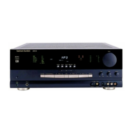
AVR 510 Audio/Video Receiver
OWNER'S MANUAL
DTS
MUTE
AUTO
TUNED ST
DOLBY D
PCM
MP3
COAXIAL
OPTICAL
1 2 3
1 2 3
ANALOG
VMAx NF
5.1 LOGIC 7 CM
DIGITAL
PRO LOGIC
3- STEREO
5 CH STEREO HALL 12
Power for the Digital Revolution.
O
O
MEMORY PRESET
L
0
C
0
R
SLEEP
O
O
O
O
LS
RS
LFE
OSD
O
O
THEATER
NIGHT
MULTI
®
®
™
Advertisement
Table of Contents

Related Manuals for Harman Kardon AVR 510


Summary of Contents for Harman Kardon AVR 510
- Page 1 AVR 510 Audio/Video Receiver OWNER’S MANUAL MUTE AUTO TUNED ST MEMORY PRESET SLEEP DOLBY D COAXIAL OPTICAL 1 2 3 1 2 3 ANALOG VMAx NF 5.1 LOGIC 7 CM DIGITAL PRO LOGIC 3- STEREO 5 CH STEREO HALL 12...
-
Page 2: Table Of Contents
AVR 510 Audio/Video Receiver Introduction Safety Information Unpacking Front Panel Controls Front Panel Information Display Rear Panel Connections Main Remote Control Functions Zone II Remote Control Functions Installation and Connections System Configuration Input Setup Surround Setup Delay Settings Speaker Setup... -
Page 3: Introduction
DVD and LD releases and Digital Television broadcasts. While complex digital systems are hard at work within the AVR 510 to make all of this happen, hookup and operation are simple. Color-keyed connections, a programmable remote control, and on-screen menus make the AVR 510 easy to use. -
Page 4: Safety Information
Safety Information Important Safety Information Verify Line Voltage Before Use Your AVR 510 has been designed for use with 120-volt AC current. Connection to a line volt- age other than that for which it is intended can create a safety and fire hazard and may damage the unit. -
Page 5: Front Panel Controls
NOTE: This switch is normally left in the “ON” position. System Power Control: When the Main Power Switch is “ON, ” press this button to turn on the AVR 510; press it again to turn MUTE AUTO TUNED ST MEMORY PRESET... - Page 6 Volume Control: Turn this knob clockwise to increase the volume, counterclockwise to decrease the volume. If the AVR 510 is muted, adjusting volume control will automatically release the unit from the silenced condition.
-
Page 7: Front Panel Information Display
Auto Indicator Main Information Display Mute Indicator Night Mode Indicator: This indicator lights when the AVR 510 is in the Night mode, which preserves the dynamic range of digital program material at low volume levels. Multiroom Indicator: This indicator lights when the multiroom system is active. - Page 8 AVR 510’s operation. Mute Indicator: This indicator lights to remind you that the AVR 510’s output has been silenced by pressing the Mute button Press the Mute button again to return to the...
-
Page 9: Rear Panel Connections
Rear Panel Connections ¡ ™ £ ¢ ∞ § ¶ • ª ‚ ⁄ ¤ ¡ Tape Inputs ™ Tape Outputs £ Video 1 Audio Inputs ¢ AM Antenna ∞ Video 1 Audio Outputs § DVD Audio Inputs ¶ FM Antenna •... -
Page 10: Rear Panel Connections
(+) terminals on the AVR 510 to the red (+) ter- minals on the speakers and the black (–) termi- nals on the AVR 510 to the black (–) terminals on the speakers. -
Page 11: Main Remote Control Functions
EzSet Sensor Microphone Light Button NOTE: The function names shown here are each button’s feature when used with the AVR 510. Most buttons have additional functions when used with other devices. See pages 41–42 for a list of these functions. - Page 12 Input Selectors: Pressing one of these buttons will perform three actions at the same time. First, if the AVR 510 is not turned on, this will power up the unit. Next, it will select the source shown on the button as the input to the AVR 510.
- Page 13 DVD players, and audio or video cassette recorders. (See page 38 for more information.) Skip Up/Down Buttons: These buttons do not have a direct function with the AVR 510, but when used with a compatibly programmed CD or DVD changer they will change the disc currently being played in the changer.
-
Page 14: Zone Ii Remote Control Functions
Multi IR jack e, this button turns the Multiroom system on and off. AVR Selector: Press this button to turn on the AVR 510. The input in use when the unit was last on will be selected. AM/FM Tuner Select: Press this button to select the Tuner as the input to the Multiroom system. -
Page 15: Installation And Connections
CD or LD player’s PCM (S/P-DIF) output. 4. Connect the coaxial or optical Digital Audio Outputs on the rear panel of the AVR 510 to the matching digital input connections on a CD-R or MiniDisc recorder. 5. Assemble the AM Loop Antenna supplied with the unit as shown below. - Page 16 The amplifier will be connected to the room’s speakers. No volume control is required, as the AVR 510 and the remote IR link will pro- vide that function. At the AVR 510, plug the audio interconnect cables into the Multiroom Output jacks ‚...
- Page 17 Amplifier In jacks ⁄ for the channels to be used with external devices. Store the jumpers in a safe place so that the AVR 510 may be used in its normal mode at a future date, if desired. When an external amplifier is used, connect the Preamp Out jacks ¤...
-
Page 18: System Configuration
AVR 510’s bass management system for the type of speakers used in your system, calibrate the output levels, and set the delay times used by the surround-sound processor. You are now ready to power up the AVR 510 to begin these final adjustments. - Page 19 Be certain to follow the (+) and (–) polarity indicators that are on the bottom of the battery compartment. 5. Turn the AVR 510 on either by pressing the System Power Control on the front panel, or via the remote by pressing the...
-
Page 20: Input Setup
However, to make it easier to establish the initial parameters for the AVR 510, it is best to select Dolby Pro Logic for most analog inputs and Dolby Digital for inputs connected to digital sources. In the case of... -
Page 21: Delay Settings
System Configuration Since the factory default for all inputs is Stereo, the phrase will initially appear in highlighted video (Figure 3). To change the sur- round mode while the cursor is next to the surround line, press the buttons until the desired surround mode’s name appears in the highlighted video. -
Page 22: Speaker Setup
, and press the Set button return to the main menu. Speaker Setup This menu tells the AVR 510 which type of speakers are in use. This is important as it adjusts the settings that determine which speakers receive low-frequency (bass) informa- tion. -
Page 23: Output Level Adjustment
When this option is selected, all bass information will be routed to the front left/right “main” speakers. • If a subwoofer is connected to the AVR 510, you have the option to have the front left/right “main” speakers reproduce bass... -
Page 24: Manual Output Level Adjustment
Using EzSet™ Harman Kardon’s exclusive EzSet remote makes it possible to quickly and accurately set the AVR 510’s output levels without the use of a sound pressure meter, although manual adjust- ment is also available. However, for the easiest set-up, follow these steps while seated in the listening position that will be used most often: 1. - Page 25 Once the settings outlined on the previous pages have been made, the AVR 510 is ready for operation. While there are some additional settings to be made, these are best done after...
-
Page 26: Operation
Turning the AVR 510 On or Off • When using the AVR 510 for the first time, you must press the Main Power Switch on the front panel to turn the unit on. This places the... -
Page 27: Surround Mode Chart
Operation Surround Mode Chart MODE FEATURES DOLBY DIGITAL Available only with digital input sources encoded with Dolby Digital data. It provides up to five separate main audio channels and a special dedicated Low-Frequency Effects channel. Available only with digital input sources encoded with DTS data. Available on special DVD, LD and audio-only discs, DTS provides up to five separate main audio channels and a special dedicated low-frequency channel. -
Page 28: Surround Mode Selection
(HDTV) system. Note that an optional, external RF demodulator is required to use the AVR 510 to listen to the Dolby Digital sound tracks available on laser discs. Connect the RF output of the LD player to... - Page 29 “Audio Select” button or in a menu screen on the disc) to send a full 5.1 feed to the AVR 510. It is also possible for the type of sig- nal feed to change during the course of a DVD playback.
-
Page 30: Tuner Operation
Stereo mode, unless the receiver detects a Dolby Digital or DTS bitstream. MP3 Audio Playback The AVR 510 is one of the first A/V receivers to provide on-board decoding for the MP3 audio format used by computers and portable audio devices. -
Page 31: Tape Recording
Once changed to an output, the setting will remain as long as the AVR 510 is turned on, unless the setting is changed in the OSD menu system, as described above. Note, however, that once the AVR 510 is turned off, the setting is cancelled. -
Page 32: Channel Direct Input
The AVR 510 is equipped for future expansion through the use of optional, external adapters for formats that the AVR 510 may not be capa- ble of processing. When an adapter is connected to the 6-Channel Direct Input ª, you may... -
Page 33: Advanced Features
Turn-On Volume Level As is the case with most audio/video receivers, when the AVR 510 is turned on, it will always return to the volume setting in effect when the unit was turned off. However, you may prefer to... - Page 34 Advanced Features the AVR 510 is turned off. Once the unit is turned off, the semi-OSD displays will remain activated, even if they were switched off for the previous listening session. To change the length of time that the semi-OSD...
-
Page 35: Multiroom Operation
Selector buttons to turn on to a specific source. As long as an IR feed to the AVR 510 has been established from the remote room, using any of... -
Page 36: Programming The Remote
Auto Search Method. Auto Search Method If the unit you wish to include in the AVR 510’s remote is not listed in the code tables in this manual or if the code does not seem to operate... -
Page 37: Learning Codes
Program/SPL Indicator flashes amber and the light under the device selector but- ton turns red. Release the buttons. 4. Press the button on the AVR 510 remote that you wish to program. Note that the Program/SPL Indicator will stop flashing. -
Page 38: Programmed Device Functions
Selectors will blink and then turn off. Example: To program the Macro 1 button so that it turns on the AVR 510, TV and a Cable Box, follow these steps: • Press the Macro 1 button Mute buttons at the same time and then release them. -
Page 39: Volume Punch-Through
If it appears that only a few functions operate, check to see whether another code set will work with more buttons. • When a button is pressed on the AVR 510 remote, the red light under the Input Selector for the product being operated should flash briefly. -
Page 40: Reassigning Device Control
Programming the Remote Reassigning Device Control Selectors Although each Input Selector is normally assigned to the category of product shown on the remote, it is possible to reassign one of these but- tons to operate a second device of another type. For example, if you have two VCRs but no satellite receiver, you may program the “SAT”... -
Page 41: Function List
Function List No. Button Name AVR Function Power Off Power Off Power Off Power On Power On Power On Mute Mute Mute AVR Select DVD Input Select DVD Select CD Input Select Tape Tape Input Select VID 1 Video 1 Select VID 2 Video 2 Select 10 VID 3... - Page 42 Function List (continued) No. Button Name AVR Function 45 Tune Up Tune Up Next Chapter 46 Direct Direct Tuner Entry 47 Clear Clear Clear 48 Preset Up Preset Tune Up Slow Forward 49 Tune Down Tune Down Prev Chapter Track Increment 50 OSD 51 D.
-
Page 43: Setup Code Tables
Setup Code Table: TV Manufacturer/Brand Setup Code Number A MARK 103 132 ADMIRAL AKAI 001 160 AMPRO 070 164 AMSTRAD ANAM 045 055 057 076 095 099 103 106 109 112 122 001 011 103 BLAUPUNKT BROKSONIC 205 206 CANDLE 001 002 003 011 CAPEHART CENTURION... - Page 44 Setup Code Table: TV (continued) MIDLAND MINERVA MITSUBISHI 001 011 030 033 042 044 100 107 115 154 160 167 168 175 176 021 031 NATIONAL 177 178 179 180 181 182 001 013 022 025 030 042 057 121 123 125 NIKEI ONKING ONWA...
- Page 45 Setup Code Table: VCR Manufacturer/Brand Setup Code Number AIWA AKAI 022 048 050 108 109 126 AMPRO AMSTRAD ANAM 037 039 089 AUDIO DYNAMICS 018 029 044 048 BROKSONIC 041 043 110 147 166 CANDLE 134 135 137 CANON 034 037 039 135 140 CAPEHART CITIZEN CRAIG...
- Page 46 Setup Code Table: VCR (continued) NORDMENDE OPTIMUS OPTONICA 057 058 ORION 147 166 PANASONIC 070 074 078 086 114 125 150 167 172 PENTAX 019 026 037 039 067 PHILCO 037 039 040 071 PHILIPS 037 039 040 058 071 075 087 PILOT PIONEER 019 027 052...
- Page 47 Setup Code Table: CD Manufacturer/Brand Setup Code Number ADCOM AIWA 156 170 AKAI AUDIO TECHNICA AUDIOACCESS AUDIOFILE CALIFORNIA AUDIO CAPETRONIC CARRERA CARVER 140 141 CASIO CLARINETTE CROWN CURTIS MATHES DENON EMERSON FISHER FRABA FUNAI GENEXXA GOLDSTAR HAITAI HARMAN KARDON 040 054 HITACHI INKEL JC PENNEY...
- Page 48 Setup Code Table: CD (continued) ONKYO 046 171 OPTIMUS 057 064 PANASONIC 119 158 PHILIPS 149 209 PIONEER 094 096 PROTON QUASAR RADIO SHACK 093 150 REALISTIC 058 093 ROTEL SAMSUNG SANSUI 134 157 SANYO 082 095 SCOTT SEARS SHARP 105 114 SHERWOOD 041 058...
- Page 49 Setup Code Table: Tape Manufacturer/Brand Setup Code Number HARMAN KARDON Setup Code Table: Audio Manufacturer/Brand Setup Code Number HARMAN KARDON Setup Code Table: DVD Manufacturer/Brand Setup Code Number APEX DIGITAL CALIFORNIA AUDIO DENON 002 019 022 034 051 003 004 GOLDSTAR HARMAN KARDON 001 032...
- Page 50 Setup Code Table: SAT Manufacturer/Brand Setup Code Number ALPHASTAR ALPHASTAR DBS ALPHASTAR DSR 422 442 AMPLICA BIRDVIEW 414 425 CAPETRONICS CHANNEL MASTER 320 321 325 361 CHAPARRAL 315 316 380 451 CITOH CURTIS MATHES DRAKE 312 313 318 413 DX ANTENNA 331 352 379 483 ECHOSTAR...
- Page 51 Setup Code Table: CBL Manufacturer/Brand Setup Code Number 001 003 011 045 048 052 059 110 ALLEGRO AMERICAST ANTRONIX ARCHER 012 014 021 031 112 BELCOR CABLE STAR 033 113 CENTURION CENTURY CITIZEN 014 111 COLOUR VOICE 069 090 COMBANO 083 084 COMTRONICS 026 037...
- Page 52 Setup Code Table: CBL (continued) PULSAR RADIO SHACK 111 112 213 053 214 RECOTON REGAL 055 056 061 099 100 101 207 REGENCY 063 115 REMBRANT SAMSUNG 037 072 186 SCIENTIFIC ATLANTA 003 018 047 048 049 051 052 110 183 184 203 204 SEAM SHERITECH SIGNAL...
-
Page 53: Troubleshooting Guide
If the system still malfunctions, a system reset may clear the problem. To clear the AVR 510’s entire system memory including tuner presets, output level settings, SOLUTION • Make certain AC power cord is plugged into a live outlet •... -
Page 54: Notes
Notes 54 NOTES... -
Page 55: Technical Specifications
Technical Specifications Audio Section Stereo Mode Continuous Average Power (FTC) 80 Watts per channel, 20Hz–20kHz, @ < 0.07% THD, both channels driven into 8 ohms Five-Channel Surround Modes Power Per Individual Channel Front L&R channels: 70 Watts per channel @ < 0.07% THD, 20Hz–20kHz into 8 ohms Center channel: 70 Watts @ <... - Page 56 250 Crossways Park Drive, Woodbury, New York 11797 www.harmankardon.com © 2000 Harman Kardon, Incorporated Part No.: J90200012000...