Table of Contents
Advertisement
Advertisement
Table of Contents

Related Manuals for Gigabyte GA-H61M-USB3-B3


Summary of Contents for Gigabyte GA-H61M-USB3-B3
- Page 1 GA-H61M-USB3-B3 User's Manual Rev. 2001 12ME-H61MB3B-2001R...
-
Page 3: Identifying Motherboard Revision
The trademarks mentioned in this manual are legally registered to their respective owners. Disclaimer Information in this manual is protected by copyright laws and is the property of GIGABYTE. Changes to the specifications and features in this manual may be made by GIGABYTE without prior notice. -
Page 4: Table Of Contents
Table of Contents GA-H61M-USB3-B3 Motherboard Layout ...............5 GA-H61M-USB3-B3 Motherboard Block Diagram ............6 Chapter 1 Hardware Installation ..................7 Installation Precautions ..................7 Product Specifications ..................8 Installing the CPU ..................10 Installing the Memory ..................11 Installing an Expansion Card ................. 11 Back Panel Connectors .................. -
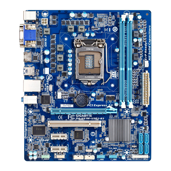
Page 5: Ga-H61M-Usb3-B3 Motherboard Layout
GA-H61M-USB3-B3 Motherboard Layout KB_MS ATX_12V LGA1155 VGA_DVI SYS_FAN HDMI R_USB30 USB_LAN Etron GA-H61M-USB3-B3 EJ168 AUDIO CPU_FAN PCIEX16 Realtek/Atheros GbE LAN SATA2 Intel ® PCIEX1_1 IT8728 PCIe to PCI Bridge PCIEX1_2 Marvell CLR_CMOS 88SE9172 CODEC F_USB2 F_AUDIO COMA F_PANEL GSATA3_0 F_USB1... -
Page 6: Ga-H61M-Usb3-B3 Motherboard Block Diagram
GA-H61M-USB3-B3 Motherboard Block Diagram 1 PCI Express x16 CPU CLK+/- (100 MHz) DDR3 1333/1066/800 MHz LGA1155 Dual Channel Memory PCIe CLK (100 MHz) RJ45 Realtek/Atheros GbE LAN PCI Express Bus PCI Express Bus 2 USB 3.0/2.0 2 PCI Express x1... -
Page 7: Chapter 1 Hardware Installation
Chapter 1 Hardware Installation Installation Precautions The motherboard contains numerous delicate electronic circuits and components which can become damaged as a result of electrostatic discharge (ESD). Prior to installation, carefully read the user's manual and follow these procedures: • Prior to installation, do not remove or break motherboard S/N (Serial Number) sticker or warranty sticker provided by your dealer. -
Page 8: Product Specifications
Dual channel memory architecture Š Support for DDR3 1333/1066/800 MHz memory modules Š Support for non-ECC memory modules Š (Go to GIGABYTE's website for the latest supported memory speeds and memory modules.) Onboard Integrated Graphics Processor: Š Graphics 1 x D-Sub port 1 x DVI-D port, supporting a maximum resolution of 1920x1200 * The DVI-D port does not support D-Sub connection by adapter. - Page 9 Internal 1 x CPU fan header Š Connectors 1 x system fan header Š 1 x front panel header Š 1 x front panel audio header Š 2 x USB 2.0/1.1 headers Š 1 x serial port header Š 1 x clearing CMOS jumper Š...
-
Page 10: Installing The Cpu
Form Factor Micro ATX Form Factor; 24.4cm x 20.5cm Š * GIGABYTE reserves the right to make any changes to the product specifications and product-related information without prior notice. Installing the CPU Read the following guidelines before you begin to install the CPU: • Make sure that the motherboard supports the CPU. -
Page 11: Installing The Memory
• Make sure that the motherboard supports the memory. It is recommended that memory of the same capacity, brand, speed, and chips be used. (Go to GIGABYTE's website for the latest supported memory speeds and memory modules.) • Always turn off the computer and unplug the power cord from the power outlet before installing the memory to prevent hardware damage. -
Page 12: Back Panel Connectors
Back Panel Connectors PS/2 Keyboard/Mouse Port Use the upper port (green) to connect a PS/2 mouse and the lower port (purple) to connect a PS/2 key- board. D-Sub Port The D-Sub port supports a 15-pin D-Sub connector. Connect a monitor that supports D-Sub connection to this port. - Page 13 Dual Display Configurations for the Onboard Graphics: This motherboard provides three video output ports: D-Sub, DVI-D, and HDMI. Dual monitor configurations are supported in operating system environment only, but not during the BIOS Setup or POST process. USB 3.0/2.0 Port The USB 3.0 port supports the USB 3.0 specification and is compatible to the USB 2.0/1.1 specification. Use this port for USB devices such as a USB keyboard/mouse, USB printer, USB flash drive and etc.
-
Page 14: Internal Connectors
Internal Connectors ATX_12V SATA2 0/1/2/3 F_PANEL CPU_FAN F_AUDIO SYS_FAN F_USB1/F_USB2 COMA GSATA3_0/1 CLR_CMOS Read the following guidelines before connecting external devices: • First make sure your devices are compliant with the connectors you wish to connect. • Before installing the devices, be sure to turn off the devices and your computer. Unplug the power cord from the power outlet to prevent damage to the devices. - Page 15 1/2) ATX_12V/ATX (2x2 12V Power Connector and 2x12 Main Power Connector) With the use of the power connector, the power supply can supply enough stable power to all the com- ponents on the motherboard. Before connecting the power connector, first make sure the power supply is turned off and all devices are properly installed.
- Page 16 3/4) CPU_FAN/SYS_FAN (Fan Headers) The motherboard has a 4-pin CPU fan header (CPU_FAN) and a 4-pin (SYS_FAN). Most fan headers possess a foolproof insertion design. When connecting a fan cable, be sure to connect it in the correct orientation (the black connector wire is the ground wire). The motherboard supports CPU fan speed con- trol, which requires the use of a CPU fan with fan speed control design.
- Page 17 DEBUG DEBUG PORT PORT 6) GSATA3_0/1 (SATA 6Gb/s Connectors, Controlled by Marvell 88SE9172 Chip) The SATA connector conform to SATA 6Gb/s standard and are compatible with SATA 3Gb/s and SATA 1.5Gb/s standard. Each SATA connector supports a single SATA device. The Marvell 88SE9172 chip supports RAID 0 and RAID 1.
-
Page 18: Front Panel Heade
8) F_PANEL (Front Panel Header) Connect the power switch, reset switch, speaker, chassis intrusion switch/sensor and system status indicator on the chassis to this header according to the pin assignments below. Note the positive and negative pins before connecting the cables. Message/Power/ Power Speaker... - Page 19 9) F_AUDIO (Front Panel Audio Header) The front panel audio header supports Intel High Definition audio (HD) and AC'97 audio. You may connect your chassis front panel audio module to this header. Make sure the wire assignments of the module con- nector match the pin assignments of the motherboard header.
- Page 20 11) COMA (Serial Port Header) The COM header can provide one serial port via an optional COM port cable. For purchasing the op- tional COM port cable, please contact the local dealer. Pin No. Definition NDCD- NSIN NSOUT NDTR- NDSR- NRTS- NCTS- NRI-...
-
Page 21: Chapter 2 Bios Setup
To see more advanced BIOS Setup menu options, you can press <Ctrl> + <F1> in the main menu of the BIOS Setup program. To upgrade the BIOS, use either the GIGABYTE Q-Flash or @BIOS utility. Q-Flash allows the user to quickly and easily upgrade or back up BIOS without entering the operating •... -
Page 22: The Main Menu
The Main Menu Once you enter the BIOS Setup program, the Main Menu (as shown below) appears on the screen. Use ar- row keys to move among the items and press <Enter> to accept or enter a sub-menu. (Sample BIOS Version: E2) CMOS Setup Utility-Copyright (C) 1984-2011 Award Software MB Intelligent Tweaker(M.I.T.) Load Fail-Safe Defaults ... -
Page 23: Mb Intelligent Tweaker(M.i.t.)
MB Intelligent Tweaker(M.I.T.) CMOS Setup Utility-Copyright (C) 1984-2011 Award Software MB Intelligent Tweaker(M.I.T.) Item Help M.I.T Current Status [Press Enter] Menu Level Advanced Frequency Settings [Press Enter] Advanced Memory Settings [Press Enter] Advanced Voltage Settings [Press Enter] ... -
Page 24: Cpu Clock Ratio
Advanced Frequency Settings CMOS Setup Utility-Copyright (C) 1984-2011 Award Software Advanced Frequency Settings Item Help CPU Clock Ratio [30X] Menu Level CPU Frequency 3.00GHz (100x30) Advanced CPU Core Features [Press Enter] >>>>> Standard Clock Control BCLK/DMI/PEG Clock Control [Disabled] x BCLK/DMI/PEG Frequency (0.1MHz) 1000... - Page 25 Core Current Limit (Amps) Allows you to set a current limit for CPU Turbo mode. When the CPU current exceeds the specified cur- rent limit, the CPU will automatically reduce the core frequency in order to reduce the current. Auto sets the current limit according to the CPU specifications. (Default: Auto) CPU Cores Enabled (Note) Allows you to determine whether to enable all CPU cores.
- Page 26 BCLK/DMI/PEG Frequency(0.1MHz) Allows you to manually set the CPU base clock and DMI/PCIe bus frequency. The adjustable range is from 800 MHz to 2000 MHz. This item is configurable only when the BCLK/DMI/PEG Clock Control op- tion is enabled. System Memory Multiplier (SPD) Allows you to set the system memory multiplier.
- Page 27 Channel Interleaving Enables or disables memory channel interleaving. Enabled allows the system to simultaneously access different channels of the memory to increase memory performance and stability. Auto lets the BIOS au- tomatically configure this setting. (Default: Auto) Rank Interleaving Enables or disables memory rank interleaving. Enabled allows the system to simultaneously access dif- ferent ranks of the memory to increase memory performance and stability.
- Page 28 Options are: Auto (default), 1~12 tRFC Options are: Auto (default), 1~255. tRTP Options are: Auto (default), 1~15. tFAW Options are: Auto (default), 1~63. Command Rate(CMD) Options are: Auto (default), 1~3. >>>>> Channel A/B Misc Timing Control IO Latency Options are: Auto (default), 1~31. Round Trip Latency Options are: Auto (default), 1~255.
-
Page 29: Standard Cmos Features
Miscellaneous Settings CMOS Setup Utility-Copyright (C) 1984-2011 Award Software Miscellaneous Settings Item Help Isochronous Support [Enabled] Menu Level Virtualization Technology [Enabled] (Note) : Move Enter: Select +/-/PU/PD: Value F10: Save ESC: Exit F1: General Help F5: Previous Values F6: Fail-Safe Defaults F7: Optimized Defaults Isochronous Support Determines whether to enable specific streams within the CPU and Chipset. -
Page 30: Advanced Bios Features
IDE Channel 2, 3 Master, 4 Master/Slave Extended IDE Drive Configure your SATA devices by using one of the two methods below: Auto Lets the BIOS automatically detect SATA devices during the POST. (Default) • None If no SATA devices are used, set this item to None so the system will skip the •... - Page 31 Allows you to set a delay time for the BIOS to initialize the hard drive as the system boots up. The ad- justable range is from 0 to 15 seconds. (Default: 0) Full Screen LOGO Show Allows you to determine whether to display the GIGABYTE Logo at system startup. Disabled displays normal POST message. (Default: Enabled) Init Display First Specifies the first initiation of the monitor display from the installed PCI graphics card, PCI Express graphics card or the onboard graphics.
-
Page 32: Integrated Peripherals
On-Chip Frame Buffer Size Frame buffer size is the total amount of system memory allocated solely for the onboard graphics con- troller. MS-DOS, for example, will use only this memory for display. Options are:32MB+2MB for GTT~ 480MB+2MB for GTT. (Default: 64MB+2MB for GTT) Integrated Peripherals CMOS Setup Utility-Copyright (C) 1984-2011 Award Software Integrated Peripherals... - Page 33 Azalia Codec Enables or disables the onboard audio function. (Default: Auto) If you wish to install a 3rd party add-in audio card instead of using the onboard audio, set this item to Disabled. Onboard H/W LAN Enables or disables the onboard LAN function. (Default: Enabled) If you wish to install a 3rd party add-in network card instead of using the onboard LAN, set this item to Disabled.
-
Page 34: Power Management Setup
Power Management Setup CMOS Setup Utility-Copyright (C) 1984-2011 Award Software Power Management Setup Item Help ACPI Suspend Type [S3(STR)] Menu Level Soft-Off by PWR-BTTN [Instant-Off] PME Event Wake Up [Enabled] Power On by Ring [Enabled] Resume by Alarm [Disabled] Date (of Month) Alarm Everyday Time (hh:mm:ss) Alarm 0 : 0 : 0... - Page 35 HPET Mode (Note) Allows you to select the HPET mode for your Windows 7/Vista operating system. Select 32-bit mode when you install 32-bit Windows 7/Vista; select 64-bit mode when you install 64-bit Windows 7/Vista. This item is configurable only when the HPET Support is set to Enabled. (Default: 32-bit mode) Power On By Mouse Allows the system to be turned on by a PS/2 mouse wake-up event.
-
Page 36: Pc Health Status
PC Health Status CMOS Setup Utility-Copyright (C) 1984-2011 Award Software PC Health Status Item Help Reset Case Open Status [Disabled] Menu Level Case Opened Vcore 1.172V DDR15V 1.516V +12V 11.779V 1.076V Current System Temperature Current CPU Temperature Current CPU FAN Speed 3375 RPM Current SYSTEM FAN Speed 0 RPM... -
Page 37: Load Fail-Safe Defaults
Slope PWM Allows you to control the CPU fan speed. This item is configurable only when CPU Smart FAN Control is set to Manual. Options are: 0.75 PWM value / C ~ 2.50 PWM value / Load Fail-Safe Defaults CMOS Setup Utility-Copyright (C) 1984-2011 Award Software MB Intelligent Tweaker(M.I.T.) Load Fail-Safe Defaults ... -
Page 38: Set Supervisor/User Password
2-11 Set Supervisor/User Password CMOS Setup Utility-Copyright (C) 1984-2011 Award Software MB Intelligent Tweaker(M.I.T.) Load Fail-Safe Defaults Standard CMOS Features Load Optimized Defaults Advanced BIOS Features Set Supervisor Password Integrated Peripherals Set User Password Power Management Setup Save &... -
Page 39: Exit Without Saving
2-13 Exit Without Saving CMOS Setup Utility-Copyright (C) 1984-2011 Award Software MB Intelligent Tweaker(M.I.T.) Load Fail-Safe Defaults Standard CMOS Features Load Optimized Defaults Quit Without Saving (Y/N)? N Advanced BIOS Features Set Supervisor Password Integrated Peripherals Set User Password ... -
Page 40: Chapter 4 Appendix
Chapter 4 Appendix 4-1 Configuring SATA Hard Drive(s) Before you begin Please prepare: • At least two SATA hard drives (to ensure optimal performance, it is recommended that you use two hard drives with identical model and capacity). If you do not want to create RAID, you may prepare only one hard drive. - Page 41 b. Stripe Size: Select the stripe block size. Options include 32 KB, 64 KB, and 128 KB. c. Quick Init: Select whether to quickly erase old data on the hard drives when creating the array. d. Cache Mode: Select write-back or write-through cache. e.
-
Page 42: Regulatory Statements
Contravention will be prosecuted. We believe that the information contained herein was accurate in all respects at the time of printing. GIGABYTE cannot, however, assume any responsibility for errors or omissions in this text. Also note that the information in this document is subject to change without notice and should not be construed as a commitment by GIGABYTE. - Page 43 - 43 -...
- Page 44 WEB address (English): http://www.gigabyte.com WEB address (Chinese): http://www.gigabyte.tw You may go to the GIGABYTE website, select your language in the language list on the top right corner of the website. • GIGABYTE Global Service System To submit a technical or non-technical (Sales/Market- ing) question, please link to: http://ggts.gigabyte.com.tw...