Table of Contents
Advertisement
Advertisement
Table of Contents

Related Manuals for Gigabyte GA-H61M-D2H


Summary of Contents for Gigabyte GA-H61M-D2H
- Page 1 GA-H61M-D2H GA-H61M-D2H-USB3 User's Manual Rev. 1001 12ME-H61MD2H-1001R...
-
Page 3: Identifying Motherboard Revision
The trademarks mentioned in this manual are legally registered to their respective owners. Disclaimer Information in this manual is protected by copyright laws and is the property of GIGABYTE. Changes to the specifications and features in this manual may be made by GIGABYTE without prior notice. -
Page 4: Table Of Contents
Table of Contents GA-H61M-D2H/GA-H61M-D2H-USB3 Motherboard Layout ..........5 GA-H61M-D2H/GA-H61M-D2H-USB3 Motherboard Block Diagram ......6 Chapter 1 Hardware Installation ..................7 Installation Precautions ................... 7 Product Specifications ..................8 Installing the CPU ..................10 Installing the Memory ..................11 Installing an Expansion Card ................11 Back Panel Connectors ................. 12 Internal Connectors .................. -
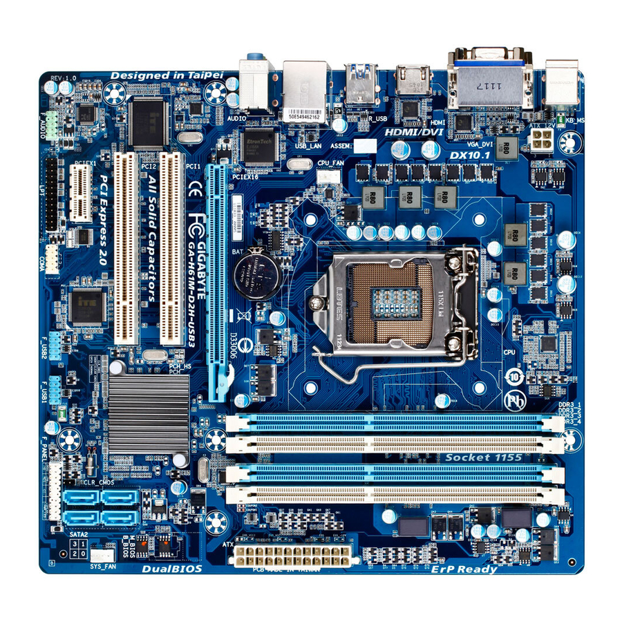
Page 5: Ga-H61M-D2H/Ga-H61M-D2H-Usb3 Motherboard Layout
F_USB1 F_AUDIO COMA F_PANEL Box Contents GA-H61M-D2H or GA-H61M-D2H-USB3 motherboard Motherboard driver disk Two SATA cables User's Manual I/O Shield The box contents above are for reference only and the actual items shall depend on the product package you obtain. -
Page 6: Ga-H61M-D2H/Ga-H61M-D2H-Usb3 Motherboard Block Diagram
GA-H61M-D2H/GA-H61M-D2H-USB3 Motherboard Block Diagram 1 PCI Express x16 CPU CLK+/- (100 MHz) LGA1155 DDR3 1333/1066/800 MHz PCIe CLK Dual Channel Memory (100 MHz) PCI Express Bus 1 PCI Express x1 D-Sub Dual BIOS DVI-D 4 SATA 3Gb/s PCI Express Bus 8 USB 2.0/1.1 j... -
Page 7: Chapter 1 Hardware Installation
Chapter 1 Hardware Installation Installation Precautions The motherboard contains numerous delicate electronic circuits and components which can become damaged as a result of electrostatic discharge (ESD). Prior to installation, carefully read the user's manual and follow these procedures: Prior to installation, do not remove or break motherboard S/N (Serial Number) sticker or •... -
Page 8: Product Specifications
Dual channel memory architecture Š Support for DDR3 1333/1066/800 MHz memory modules Š Support for non-ECC memory modules Š (Go to GIGABYTE's website for the latest supported memory speeds and memory modules.) Onboard Chipset: Š 1 x D-Sub port Graphics 1 x DVI-D port, supporting a maximum resolution of 1920x1200 * The DVI-D port does not support D-Sub connection by adapter. - Page 9 Support for ON/OFF Charge Š Support for Cloud OC Š Support for 3TB+ Unlock Š Support for TouchBIOS Š Support for Q-Share Š Bundled Norton Internet Security (OEM version) Š Software j Only for GA-H61M-D2H. k Only for GA-H61M-D2H-USB3. - 9 -...
-
Page 10: Installing The Cpu
Form Factor Micro ATX Form Factor; 24.4cm x 22.5cm Š * GIGABYTE reserves the right to make any changes to the product specifications and product-related information without prior notice. Installing the CPU Read the following guidelines before you begin to install the CPU: Make sure that the motherboard supports the CPU. -
Page 11: Installing The Memory
Make sure that the motherboard supports the memory. It is recommended that memory of the • same capacity, brand, speed, and chips be used. (Go to GIGABYTE's website for the latest supported memory speeds and memory modules.) Always turn off the computer and unplug the power cord from the power outlet before installing •... -
Page 12: Back Panel Connectors
(The item name may differ from operating system. Refer to the figure below for details.) In Windows 7, select Start>Control Panel>Hardware and Sound>Sound>Playback, set Intel(R) Display Audio to the default playback device. j Only for GA-H61M-D2H. k Only for GA-H61M-D2H-USB3. (Note) The DVI-D port does not support D-Sub connection by adapter. - Page 13 To configure 7.1-channel audio, you have to use an HD front panel audio module and enable the multi-channel audio feature through the audio driver. k Only for GA-H61M-D2H-USB3. When removing the cable connected to a back panel connector, first remove the cable from your •...
-
Page 14: Internal Connectors
Internal Connectors ATX_12V F_AUDIO F_USB1/2 CPU_FAN COMA SYS_FAN SATA2 0/1/2/3 CLR_CMOS F_PANEL Read the following guidelines before connecting external devices: First make sure your devices are compliant with the connectors you wish to connect. • Before installing the devices, be sure to turn off the devices and your computer. Unplug the •... - Page 15 1/2) ATX_12V/ATX (2x2 12V Power Connector and 2x12 Main Power Connector) With the use of the power connector, the power supply can supply enough stable power to all the com- ponents on the motherboard. Before connecting the power connector, first make sure the power supply is turned off and all devices are properly installed.
-
Page 16: Fan Headers
3/4) CPU_FAN/SYS_FAN (Fan Headers) The motherboard has a 4-pin CPU fan header (CPU_FAN) and a 4-pin system fan header (SYS_FAN). Most fan headers possess a foolproof insertion design. When connecting a fan cable, be sure to connect it in the correct orientation (the black connector wire is the ground wire). The motherboard supports CPU fan speed control, which requires the use of a CPU fan with fan speed control design. -
Page 17: Front Panel Heade
6) F_PANEL (Front Panel Header) Connect the power switch, reset switch, speaker, and system status indicator on the chassis to this header according to the pin assignments below. Note the positive and negative pins before connecting the cables. Message/Power/ Power Sleep LED Switch Speaker... -
Page 18: Front Panel Audio Header
7) F_AUDIO (Front Panel Audio Header) The front panel audio header supports Intel High Definition audio (HD) and AC'97 audio. You may connect your chassis front panel audio module to this header. Make sure the wire assignments of the module con- nector match the pin assignments of the motherboard header. - Page 19 9) COMA (Serial Port Header) The COM header can provide one serial port via an optional COM port cable. For purchasing the op- tional COM port cable, please contact the local dealer. Pin No. Definition NDCD- NSIN NSOUT NDTR- NDSR- NRTS- NCTS- NRI-...
-
Page 20: Battery
11) CLR_CMOS (Clearing CMOS Jumper) Use this jumper to clear the CMOS values (e.g. date information and BIOS configurations) and reset the CMOS values to factory defaults. To clear the CMOS values, use a metal object like a screwdriver to touch the two pins for a few seconds. -
Page 21: Chapter 2 Bios Setup
To see more advanced BIOS Setup menu options, you can press <Ctrl> + <F1> in the main menu of the BIOS Setup program. To upgrade the BIOS, use either the GIGABYTE Q-Flash or @BIOS utility. Q-Flash allows the user to quickly and easily upgrade or back up BIOS without entering the operating •... -
Page 22: The Main Menu
Once you enter the BIOS Setup program, the Main Menu (as shown below) appears on the screen. Use ar- row keys to move among the items and press <Enter> to accept or enter a sub-menu. (Sample BIOS Version: GA-H61M-D2H E6) CMOS Setup Utility-Copyright (C) 1984-2011 Award Software MB Intelligent Tweaker(M.I.T.) -
Page 23: Mb Intelligent Tweaker(M.i.t.)
MB Intelligent Tweaker(M.I.T.) CMOS Setup Utility-Copyright (C) 1984-2011 Award Software MB Intelligent Tweaker(M.I.T.) Item Help M.I.T Current Status [Press Enter] Menu Level Advanced Frequency Settings [Press Enter] Advanced Memory Settings [Press Enter] Advanced Voltage Settings [Press Enter] ... -
Page 24: Cpu Clock Ratio
M.I.T. Current Status This screen provides information on CPU/memory frequencies/parameters. Advanced Frequency Settings CMOS Setup Utility-Copyright (C) 1984-2011 Award Software Advanced Frequency Settings Item Help CPU Clock Ratio [31X] Menu Level CPU Frequency 3.10GHz (100x31) Advanced CPU Core Features [Press Enter] >>>>>... - Page 25 Intel(R) Turbo Boost Tech. (Note) Allows you to determine whether to enable the Intel CPU Turbo Boost technology. Auto lets the BIOS automatically configure this setting. (Default: Auto) Turbo Ratio (1-Core)/(2-Core)/(3-Core)/(4-Core) (Note) Allows you to set the CPU Turbo ratios for different number of active cores. Auto sets the CPU Turbo ratios according to the CPU specifications.
- Page 26 Bi-Directional PROCHOT (Note) Auto Lets the BIOS automatically configure this setting. (Default) Enabled When the CPU or chipset detects that an overheating is occurring, PROCHOT sig- nals will be emitted to lower CPU performance to decrease heat production. Disabled Only allows the CPU to detect whether an overheating is occurring to emit PRO- CHOT signals.
- Page 27 Advanced Memory Settings CMOS Setup Utility-Copyright (C) 1984-2011 Award Software Advanced Memory Settings Item Help System Memory Multiplier (SPD) [Auto] Menu Level Memory Frequency (Mhz) 1333 1333 Performance Enhance [Turbo] DRAM Timing Selectable (SPD) [Auto] Profile DDR Voltage 1.5V Profile VTT Voltage 1.05V x Channel Interleaving Auto x Rank Interleaving...
- Page 28 >>>>> Channel A/B Timing Settings CMOS Setup Utility-Copyright (C) 1984-2011 Award Software Channel A Timing Settings Item Help >>>>> Channel A Standard Timing Control Menu Level x CAS Latency Time Auto x tRCD Auto x tRP Auto x tRAS Auto >>>>>...
- Page 29 Command Rate(CMD) Options are: Auto (default), 1~3. >>>>> Channel A/B Misc Timing Control IO Latency Options are: Auto (default), 1~31. Round Trip Latency Options are: Auto (default), 1~255. Advanced Voltage Settings CMOS Setup Utility-Copyright (C) 1984-2011 Award Software Advanced Voltage Settings Item Help ****** Mother Board Voltage Control ****** Menu Level ...
-
Page 30: Standard Cmos Features
Miscellaneous Settings CMOS Setup Utility-Copyright (C) 1984-2011 Award Software Miscellaneous Settings Item Help Isochronous Support [Enabled] Menu Level Virtualization Technology (Note) [Enabled] : Move Enter: Select +/-/PU/PD: Value F10: Save ESC: Exit F1: General Help F5: Previous Values F6: Fail-Safe Defaults F7: Optimized Defaults Isochronous Support Determines whether to enable specific streams within the CPU and Chipset. -
Page 31: Advanced Bios Features
IDE Channel 2, 3 Master Extended IDE Drive Configure your SATA devices by using one of the two methods below: Auto Lets the BIOS automatically detect SATA devices during the POST. (Default) • None If no SATA devices are used, set this item to None so the system will skip the •... - Page 32 Allows you to set a delay time for the BIOS to initialize the hard drive as the system boots up. The ad- justable range is from 0 to 15 seconds. (Default: 0) Full Screen LOGO Show Allows you to determine whether to display the GIGABYTE Logo at system startup. Disabled displays normal POST message. (Default: Enabled) Init Display First Specifies the first initiation of the monitor display from the installed PCI graphics card, PCI Express graphics card, or the onboard graphics.
-
Page 33: Integrated Peripherals
Azalia Codec Enables or disables the onboard audio function. (Default: Auto) If you wish to install a 3rd party add-in audio card instead of using the onboard audio, set this item to Disabled. k Only for GA-H61M-D2H-USB3. - 33 -... -
Page 34: Power Management Setup
Selects an operating mode for the onboard parallel (LPT) port. Options are: SPP (Standard Parallel Port) (default), EPP (Enhanced Parallel Port), ECP (Extended Capabilities Port), ECP+EPP. k Only for GA-H61M-D2H-USB3. Power Management Setup CMOS Setup Utility-Copyright (C) 1984-2011 Award Software... - Page 35 ACPI Suspend Type Specifies the ACPI sleep state when the system enters suspend. S1(POS) Enables the system to enter the ACPI S1 (Power on Suspend) sleep state. In S1 sleep state, the system appears suspended and stays in a low power mode. The system can be resumed at any time.
-
Page 36: Pc Health Status
KB Power ON Password Set the password when Power On by Keyboard is set to Password. Press <Enter> on this item and set a password with up to 5 characters and then press <Enter> to accept. To turn on the system, enter the password and press <Enter>. -
Page 37: Load Fail-Safe Defaults
Current CPU/SYSTEM FAN Speed (RPM) Displays current CPU/system fan speed. CPU Warning Temperature Sets the warning threshold for CPU temperature. When CPU temperature exceeds the threshold, BIOS will emit warning sound. Options are: Disabled (default), 60 C/140 F, 70 C/158 F, 80 C/176 C/194... -
Page 38: Load Optimized Defaults
2-10 Load Optimized Defaults CMOS Setup Utility-Copyright (C) 1984-2011 Award Software MB Intelligent Tweaker(M.I.T.) Load Fail-Safe Defaults Standard CMOS Features Load Optimized Defaults Advanced BIOS Features Set Supervisor Password Integrated Peripherals Set User Password Power Management Setup Save &... -
Page 39: Save & Exit Setup
2-12 Save & Exit Setup CMOS Setup Utility-Copyright (C) 1984-2011 Award Software MB Intelligent Tweaker(M.I.T.) Load Fail-Safe Defaults Standard CMOS Features Load Optimized Defaults Save to CMOS and EXIT (Y/N)? Y Advanced BIOS Features Set Supervisor Password Integrated Peripherals Set User Password ... -
Page 40: Chapter 3 Drivers Installation
Chapter 3 Drivers Installation Before installing the drivers, first install the operating system. • After installing the operating system, insert the motherboard driver disk into your optical drive. • The driver Autorun screen is automatically displayed which looks like that shown in the screen shot below. -
Page 41: Regulatory Statements
Contravention will be prosecuted. We believe that the information contained herein was accurate in all respects at the time of printing. GIGABYTE cannot, however, assume any responsibility for errors or omissions in this text. Also note that the information in this document is subject to change without notice and should not be construed as a commitment by GIGABYTE. - Page 42 - 42 -...
- Page 43 - 43 -...
- Page 44 WEB address (English): http://www.gigabyte.com WEB address (Chinese): http://www.gigabyte.tw You may go to the GIGABYTE website, select your language in the language list on the top right corner of the website. • GIGABYTE Global Service System To submit a technical or non-technical (Sales/Market- ing) question, please link to: http://ggts.gigabyte.com.tw...