Table of Contents
Advertisement
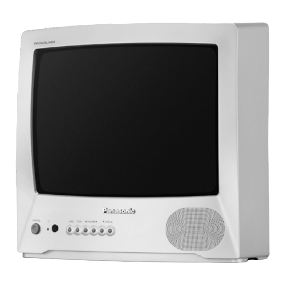
TELEVISION
Power source
Consumption
Antenna input jack
Color systems
Tuning system
Channel capability
Picture tube (visual diagonal)
Audio system
Video input jack
Dimension (width, height, depth)
Weight
Remote Control Transmiter:
Power Source
Infrared Length
Number of Buttons
Dimensions (W x H x D)
Specifications are subject to change without notice. Weight and dimensions shown are approximate.
TC-14A12P
110/220 V AC, 60 Hz automatic switch
55 W
75 W - VHF/UHF/Cable
NTSC/PAL-N/AUTO/PAL-M
F.S.T.
2 to 13 (VHF)
14 to 69 (UHF)
1 to 125 (Cable)
33 cm
3 W max (RMS)
1 (back of unit)
370 x 349 x 374 mm
9,6 kg
3V (2 AA type batteries)
9500 A (Angstron)
29 keys
(54 x 27 x 135) mm
TC-20B12
110/220 V AC, 60 Hz automatic switch
69 W
75 W - VHF/UHF/Cable
NTSC/PAL-N/AUTO/PAL-M
F.S.T.
2 to 13 (VHF)
14 to 69 (UHF)
1 to 125 (Cable)
48 cm
3 W max (RMS)
1 (back of unit)
502 x 455 x 471 mm
17 kg
Supplied Accessories:
• 1 Remote Control Transmitter
• 1 300 /75 Aerial Adaptor
• 2 "AA" type batteries
• 1 Internal antenna (for TC-14A12P only)
Advertisement
Table of Contents

Related Manuals for Panasonic TC-14A12P


Summary of Contents for Panasonic TC-14A12P
- Page 1 Number of Buttons 29 keys • 2 “AA” type batteries Dimensions (W x H x D) (54 x 27 x 135) mm • 1 Internal antenna (for TC-14A12P only) Specifications are subject to change without notice. Weight and dimensions shown are approximate.
-
Page 2: Table Of Contents
TC-14A12P / TC-20B12 WARNING This service information is designed for experienced repair technicians only and is not designed for use by the general public. It does not contain warnings or cautions to advise non-technician individuals of potential dangers in attempting to service a product. -
Page 3: Operation Guide
Location of Controls (TC-20B12) Location of Controls (TC-20B12) Location of Controls (TC-20B12) Location of Controls (TC-20B12) Location of Controls (TC-20B12) Location of Controls (TC-14A12P) Location of Controls (TC-14A12P) Location of Controls (TC-14A12P) Location of Controls (TC-14A12P) Location of Controls (TC-14A12P) - Page 4 Location of Controls Location of Controls Location of Controls Location of Controls Location of Controls Remote Control Remote Control Remote Control Remote Control Remote Control Installing the Batteries Installing the Batteries Installing the Batteries Installing the Batteries Installing the Batteries REMOTE CONTROL REMOTE CONTROL REMOTE CONTROL...
- Page 5 Installation Installation Installation Operation of TV Controls Operation of TV Controls Operation of TV Controls Operation of TV Controls Operation of TV Controls Installation Installation Outdoor Antenna Connection Outdoor Antenna Connection Outdoor Antenna Connection Outdoor Antenna Connection Outdoor Antenna Connection 1.
- Page 6 Note: Note: Note: 4. 4. 4. 4. 4. V V V V V olume Buttons olume Buttons olume Buttons olume Buttons olume Buttons (+, –) (+, –) (+, –) (+, –) (+, –) Note: Note: General Operation General Operation General Operation General Operation General Operation A numerical and...
- Page 7 General Operation General Operation General Operation General Operation General Operation General Operation General Operation General Operation General Operation General Operation R-TUNE R-TUNE R-TUNE R-TUNE R-TUNE Button Button Button Button Button 9. 9. 9. 9. 9. PICTURE MENU PICTURE MENU PICTURE MENU PICTURE MENU PICTURE MENU Button Button...
- Page 8 Main Menu List Main Menu List Tuning Procedures Tuning Procedures Main Menu List Main Menu List Main Menu List Tuning Procedures Tuning Procedures Tuning Procedures When the MAIN MENU button is pressed, the icon menu is displayed. This gives access to picture, sound, function, Channel Selection Channel Selection Channel Selection...
- Page 9 Tuning Procedures Tuning Procedures Tuning Procedures Tuning Procedures Tuning Procedures Tuning Procedures Tuning Procedures Tuning Procedures Tuning Procedures Tuning Procedures MAIN MENU MAIN MENU MAIN MENU MAIN MENU MAIN MENU MAIN MENU MAIN MENU MAIN MENU MAIN MENU MAIN MENU POWER POWER FUNC TV/AV...
- Page 10 Tuning Procedures Tuning Procedures Tuning Procedures Tuning Procedures Tuning Procedures Tuning Procedures Tuning Procedures Tuning Procedures Tuning Procedures Tuning Procedures Auto Tuning Mode Auto Tuning Mode Auto Tuning Mode Manual Tuning Mode Manual Tuning Mode Manual Tuning Mode Manual Tuning Mode Manual Tuning Mode Auto Tuning Mode Auto Tuning Mode...
- Page 11 Tuning Procedures Tuning Procedures Tuning Procedures Tuning Procedures Tuning Procedures Tuning Procedures Tuning Procedures Tuning Procedures Tuning Procedures Tuning Procedures Fine Tuning Mode Fine Tuning Mode Fine Tuning Mode Fine Tuning Mode Fine Tuning Mode Channel Skip Mode Channel Skip Mode Channel Skip Mode Channel Skip Mode Channel Skip Mode...
- Page 12 Tuning Procedures Tuning Procedures Tuning Procedures Supplementary Remote Control Operations Supplementary Remote Control Operations Tuning Procedures Tuning Procedures Supplementary Remote Control Operations Supplementary Remote Control Operations Supplementary Remote Control Operations Color System Mode Color System Mode Color System Mode Color System Mode Color System Mode Picture Menu Picture Menu...
- Page 13 Supplementary Remote Control Operations Supplementary Remote Control Operations Supplementary Remote Control Operations Supplementary Remote Control Operations Supplementary Remote Control Operations Supplementary Remote Control Operations Supplementary Remote Control Operations Supplementary Remote Control Operations Supplementary Remote Control Operations Supplementary Remote Control Operations Sound Menu Sound Menu Sound Menu...
- Page 14 Troubleshooting Chart Troubleshooting Chart Supplementary Remote Control Operations Supplementary Remote Control Operations Supplementary Remote Control Operations Supplementary Remote Control Operations Supplementary Remote Control Operations Troubleshooting Chart Troubleshooting Chart Troubleshooting Chart ON MUTE (Mute/Closed Caption) ON MUTE (Mute/Closed Caption) ON MUTE (Mute/Closed Caption) ON MUTE (Mute/Closed Caption) ON MUTE (Mute/Closed Caption) Before you call for service, determine the symptoms and make a few simple checks, as shown below.
-
Page 15: Ic 601 - Pins And Functions
TC-14A12P / TC-20B12 IC601 (TDA9381PS/N2/3) - Pins and Functions - 15 -... - Page 16 TC-14A12P / TC-20B12 IC601 - Pins and Functions Nome Nº Descrição P1.3/T1 port 1.3 or Counter/Timer 1 input P1.6/SCL port 1.6 or I 2 C-bus clock line P1.7/SDA port 1.7 or I 2 C-bus data line P2.0/TPWM port 2.0 or Tuning PWM output P3.0/ADC0/PWM0...
-
Page 17: Ic601 And Ic451 Voltage Table
TC-14A12P / TC-20B12 IC601 - Pins and Functions Nome Nº Descrição BLKIN black current input / (V-guard input, note 2) Red output Green output Blue output VDDA analog supply of Teletext decoder and digital supply of TV-processor (3.3 V) OTP Programming Voltage VDDC digital supply to core (3.3 V) -
Page 18: Ic601 - Block Diagram
TC-14A12P / TC-20B12 IC601 - Block Diagram - 18 -... -
Page 19: General Summary
Vertical Magnetic Field -0.1 ±0.03 (BRASIL) Colour Temperature TC-14A12P: (High Light) x= 0.260±0.01, y=0.265 ±0.01, Y=300 (nit) (Low Light) x= 0.243±0.01, y=0.255 ±0.01, Y=6.5 (nit) TC-20B12: (High Light) x= 0.270±0.01, y=0.275 ±0.01, Y=155 (nit) (Low Light) x= 0.245±0.01, y=0.235 ±0.01, Y=7.0 (nit) -
Page 20: Service Mode
TC-14A12P / TC-20B12 TO EXIT SERVICE MODE AND RETURN TO THE NORMAL TO ENTER IN THE SERVICE MODE: STATE: 1. Adjust the volume for the minimum. 2. Adjustment the “OFF TIMER” function for 30 minutes. Press the “NORMAL” key on the remote control unit or turn off 3. -
Page 21: Equipment Required
2.3. Connect the high voltage meter in the CRT anode pin, and • Degaussing Coil confirm that the high voltage is within a range of [A]: • TC-14A12P [A]=24.5 +0.7kV _ 1.5kV • White Pattern Generator [A]=26.5 +0.7kV _ 1.5kV •... -
Page 22: Ntsc Sub-Tint Calibration
TC-14A12P / TC-20B12 NTSC SUB-TINT CALIBRATION WHITE QUALITY CALIBRATION 1. PREPARATION: 1. PREPARATION: 1.1. Connect the oscilloscope to TPL1 (R OUT) in serie with a 1.1. Adjust the HELMHOLTZ device to local magnetic field. Hori- 10K resistor. zontal: 0 ± 0.003 X 10⁻⁴T 1.2. -
Page 23: Crt Cut Off Calibration
TC-14A12P / TC-20B12 5. VERTICAL HEIGHT (V-AMP 50HZ) CALIBRATION 2. CALIBRATION: 5.1. Receive a PAL-N Philips pattern. 5.2. Adjust V-AMP-50Hz so that the Philips pattern’s circle height [1] LOW LIGHT CALIBRATION be the same dimension of the width. 1. Adjust S-BRT, so that Y = Y(L). -
Page 24: Color Purity Adjustment
TC-14A12P / TC-20B12 COLOR PURITY ADJUSTMENT CONVERGENCE CALIBRATION 1. Position the CRT face turned to east or west. 1. Receive a crosshatch pattern and set Contrast control to the maximum position. 2. Set Bright and Contrast controls to their maximum positions. -
Page 25: Eeprom - Memory Maps
TC-14A12P / TC-20B12 Power Source Voltages - 25 -... -
Page 26: Main Board Schematic Diagram
TC-14A12P / TC-20B12 Main Board Schematic Diagram - TC-14A12P / TC-20B12 - 26 -... -
Page 27: Crt Board Schematic Diagram
TC-14A12P / TC-20B12 - 27 -... -
Page 28: Main Board Conductor View
TC-14A12P / TC-20B12 Main Board Conductor View (left / component side) - 28 -... - Page 29 TC-14A12P / TC-20B12 Main Board Conductor View (right / component side) - 29 -...
- Page 30 TC-14A12P / TC-20B12 Main Board Conductor View (left / foil side) - 30 -...
- Page 31 TC-14A12P / TC-20B12 Main Board Conductor View (right / foil side) - 31 -...
-
Page 32: Waveform
TC-14A12P / TC-20B12 Waveform - 32 -... - Page 33 TC-14A12P / TC-20B12 - 33 -...
- Page 34 TC-14A12P / TC-20B12 - 34 -...
-
Page 35: Parts Location
TC-14A12P / TC-20B12 Parts Location - 35 -... -
Page 36: Packing And Acessories
TC-14A12P / TC-20B12 Packing and Acessories Replacement Mechanical Parts List - 36 -... -
Page 37: Replacement Electrical Parts List
TC-14A12P / TC-20B12 Replacement Electrical Parts List - 37 -... - Page 38 TC-14A12P / TC-20B12 - 38 -...
- Page 39 TC-14A12P / TC-20B12 - 39 -...
- Page 40 TC-14A12P / TC-20B12 - 40 -...