Advertisement
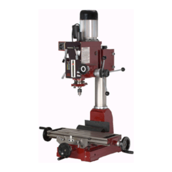
Geared Head
Drill / Mill Machine
A s s e m b l y & O p e r a t i n g I n s t r u c t i o n s
3491 Mission Oaks Blvd., Camarillo, CA 93011
Visit our Web site at http://www.harborfreight.com
READ AND UNDERSTAND ALL WARNINGS
AND INSTRUCTIONS BEFORE USE.
©
Copyright
2005 by Harbor Freight Tools
artwork contained herein may be reproduced in any shape or form without the express written
consent of Harbor Freight Tools.
For technical questions and replacement parts, please call 1-800-444-3353.
Model 42827
TO PREVENT SERIOUS INJURY,
®
. All rights reserved. No portion of this manual or any
42827
42827
42827
42827
®
Advertisement
Table of Contents

Related Manuals for Central Machinery 42827


Summary of Contents for Central Machinery 42827
- Page 1 AND INSTRUCTIONS BEFORE USE. © Copyright 2005 by Harbor Freight Tools artwork contained herein may be reproduced in any shape or form without the express written consent of Harbor Freight Tools. For technical questions and replacement parts, please call 1-800-444-3353.
-
Page 2: Specifications
It must be understood by the operator that common sense and caution are factors which cannot be built into this product, but must be supplied by the operator. Page 2 SKU # 42827 SPECIFICATIONS Drill Cap:... - Page 3 12. REMOVE ADJUSTING KEYS AND WRENCHES. Be sure that keys and adjusting wrenches are removed from the tool or machine work surface before operation. 13. AVOID UNINTENTIONAL STARTING. Be sure that you are prepared to begin work before turning the start switch on. Page 3 SKU # 42827...
- Page 4 Do not use the tool if any switch does not turn on and off properly. 17. REPLACEMENT PARTS AND ACCESSORIES. When servicing, use only identical replacement parts intended for use with this tool. Replacement parts are available from Harbor Freight Tools. Use of any other parts will void the warranty.
- Page 5 FEATURES AND CONTROLS OF THE #42827 DRILL / MILL MACHINE Column Head Collar Head Collar Lock Bolt Head Crank Lock Nut Oil Drain Plug Table Feed Wheel Travel Stop Knob Red Bush Button Green Push Button Page 5 SKU # 42827 Figure 1.
-
Page 6: Unpacking And Installation
Before operation, it is critical to level the work surface both lengthwise and crosswise, using a precision level. It will not be possible to maintain accuracy of machined parts if the mill is not properly leveled to start. Page 6 SKU # 42827 UNPACKING AND INSTALLATION INSTALLATION CLEANING AND LUBRICATION... -
Page 7: Basic Operation
For drilling holes that pass through the workpiece, set the stop gauge in its uppermost position. Page 7 SKU # 42827 BASIC OPERATION by loosening the Figure 3. - Page 8 (#21). Rotate the spindle slightly to engage the gears, then replace the arbor bolt cover. Recheck the lever setting, and then turn the power on. Levers rpm @ 60Hz 95 Page 8 SKU # 42827 Figure 6. Machine Speed Lever Settings. Figure 5. Adjusting the Gib Strips. 1500...
- Page 9 Tighten the arbor bolt securely, but do not overtighten. Replace the arbor bolt cover. Additional Tools and Accessories You Will Find Helpful Your Drill Mill machine is equipped with an R-8 spindle taper. Many tools, bits, and acessories are available for this standard. Taper Drills...
-
Page 10: Troubleshooting
Adjust the table or depth stop to avoid drilling into the table. Shut off the power, remove the drill bit or cutting tool, and clean the table before leaving the machine. Always use clamps or a vise to hold the workpiece, to prevent it from moving, rotation or flying off while being machined. - Page 11 The chuck is loose. Tighten the chuck. The drill bit or cutter is dull. Sharpen or replace it. Be sure to use cutting fluid to preserve tool life. The workpiece is not held firmly. Check the clamps or vise you are using, and assure that the workpiece cannot move.
-
Page 12: Electrical Wiring
NOTICE: 110 Volt systems deliver highly energetic currents which are Do not operate this machine without first obtaining professional installation and safety inspection to prevent operator injury. Page 12 SKU # 42827 ELECTRICAL WIRING capable of causing lethal injury. WIRING DIAGRAM... -
Page 13: Maintenance
BY THE BUYER. THE BUYER ASSUMES ALL RISK AND LIABILITY ARISING OUT OF HIS OR HER REPAIRS TO THE ORIGINAL PRODUCT OR REPLACEMENT PARTS THERETO, OR ARISING OUT OF HIS OR HER INSTAL- LATION OF REPLACEMENT PARTS THERETO. Page 13 SKU # 42827 MAINTENANCE PLEASE READ THE FOLLOWING CAREFULLY... - Page 14 1-36 Sleeve 1-37 Gear 1-38 1-39 Handle Rod 1-40 Knob 1-41 Ball Bearing (80202) 1-42 Inner Ring Page 14 SKU # 42827 Quantity Description 1-43 Shaft 1-44 Micro Adjusting Indicator 1-45 Worm Cover 1-46 Ball Bearing (202G) 1-47 Worm Shaft...
- Page 15 1-158 Knob 1-184 Screw 1-185 Washer 1-187 Washer 1-188 Phillips Head Recessed Screw 1-189 Travel Switch Base A 1-190 Travel Switch Base B Page 15 SKU # 42827 DRILL MILL MACHINE, PARTS LIST Quantity Description 2-01 Table Handle with Wheel 2-02...
- Page 16 VERTICAL MILLING MACHINE, HEAD PARTS DIAGRAM Please refer to Parts List on Pages 14 and 15. NOTE: When ordering parts from this diagram, use prefix “1”. (example: P/N 1-01 Arbor Bolt Cover) Page 16 SKU # 42827...
- Page 17 VERTICAL MILLING MACHINE, BASE PARTS DIAGRAM Please refer to Parts List on Page 15. NOTE: When ordering parts from this diagram, use prefix “2”. (example: P/N 2-01 Table Handle with Wheel) Page 17 SKU # 42827...