Table of Contents
Advertisement
Quick Links
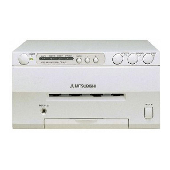
COLOUR VIDEO COPY PROCESSOR
MODEL
CP910E
OPERATION MANUAL
ALARM
SHEET
PAPER
S-VIDEO
THIS OPERATION MANUAL IS IMPORTANT
TO YOU.
PLEASE READ IT BEFORE USING YOUR
COLOUR VIDEO COPY PROCESSOR.
This video copy processor complies with the requirements of the EC Directive
89/336/EEC, 73/23/EEC, 93/42/EEC and 93/68/EEC.
The electro-magnetic susceptibility has been chosen at a level that gains proper
operation in residential areas, on business and light industrial premises and on
small-scale enterprises, inside as well as outside of the buildings. All places of
operation are characterised by their connection to the public low voltage power
supply system.
Advertisement
Table of Contents

Related Manuals for Mitsubishi CP910E


Summary of Contents for Mitsubishi CP910E
-
Page 1: Operation Manual
COLOUR VIDEO COPY PROCESSOR MODEL CP910E OPERATION MANUAL ALARM SHEET PAPER S-VIDEO THIS OPERATION MANUAL IS IMPORTANT TO YOU. PLEASE READ IT BEFORE USING YOUR COLOUR VIDEO COPY PROCESSOR. This video copy processor complies with the requirements of the EC Directive 89/336/EEC, 73/23/EEC, 93/42/EEC and 93/68/EEC. -
Page 2: Table Of Contents
CONTENTS Contents ....................2 Safety precautions ................3-5 Special features ..................6 Unpacking ..................... 7 Features and functions ................. 8-10 Front panel ..................... 8 Rear panel ..................... 9 Remote control unit ................10 Connections ..................11 Connection with a monitor ..............11 Connection with video or S-video signal equipment ...... -
Page 3: Safety Precautions
SAFETY PRECAUTIONS In the interest of safety, please observe the following precautions: POWER REQUIREMENT This Colour Video Copy Processor is designed for operation on 220-240V, 50Hz AC. Never connect to any outlet or power supply having a different voltage or frequency. WARNING: THIS APPARATUS MUST BE EARTHED. - Page 4 SAFETY PRECAUTIONS INSTALLATION LOCATIONS MAINTAIN GOOD VENTILATION Ventilation slots and holes are provided on this unit. Place the unit on a hard and level surface and locate at least 10 cm (4 inches) from walls to insure proper ventilation. When putting the unit on the system rack, take a space between the unit and the back of the rack.
-
Page 5: Other Cautions
SAFETY CHECKS Periods: According to the recommendations of the manufacturer of the medical device. Scope: a) Visual inspection Housing, leads, controls, displays, labels/ markings, accessories, operation manual. b) Function test Testing of functions (according to operation manual) as well as compatibility and usability of device and accessories. -
Page 6: Special Features
SPECIAL FEATURES SPECIAL FEATURES AVAILABLE IN VARIOUS MEDICAL FIELDS, INCLUDING ENDOSCOPY DIAGNOSIS 3 kinds of colouring characteristics (gamma curve) are employed, which are the best for medical diagnostic devices, including endoscope requiring precise images and ultrasound diagnostic equipment etc. The colour is reproducible for each diagnostic equipment with easy operation. -
Page 7: Unpacking
UNPACKING UNPACKING Take the unit out of the box by the following procedures. Make sure to check the contents. 1 1 1 1 1 Open the top of the box. 2 2 2 2 2 Remove the cushion with contents. Be careful not to drop the contents. -
Page 8: Features And Functions
FEATURES & FUNCTIONS FRONT PANEL 9 A B 6 8 7 ALARM SHEET PAPER S-VIDEO 1 1 1 1 1 pressed, the picture on the monitor screen switches POWER BUTTON (INDICATOR) between the picture of the input signal (source image) and Press to turn on power. -
Page 9: Rear Panel
FEATURES & FUNCTIONS REAR PANEL REMOTE S-VIDEO VIDEO AC LINE Potential equalization connector This is used to equalize the potential of the equipment connected to the unit. For details, refer to the installation instruction of the equipment to be connected. 1 1 1 1 1 4 4 4 4 4 REMOTE TERMINAL 2 (MINI DIN 8 PIN) -
Page 10: Remote Control Unit
REMOTE CONTROL UNIT 5 5 5 5 5 SET BUTTON Press to go to SAVE PRG. Repress to memorize the values and exit the MENU mode. See pages 28-29. 6 6 6 6 6 DISPLAY STOP BUTTONS COLOR FIELD Press to cancel the printing process and start mechanical PROG. -
Page 11: Connections
CONNECTIONS The functions of this unit can be set by the menu screens displayed on the monitor. • Connection with a monitor • Connection with VIDEO/S-VIDEO signal equipment Connect this unit with a monitor to check the images to be printed and the images stored in memory. The following example shows the connection with a video signal and S-video signal equipment. -
Page 12: Before Operation
BEFORE OPERATION Before printing, 1. Unlock the printing unit. (See below) 2. Install the print paper and ink cassette. (pages 12-15) PAPER SHEET SET When using this unit for printing, make sure to use the following types of paper sheet and ink sheet set. 2 2 2 2 2 PAPER SHEET SET Product name... -
Page 13: Installation Of Ink Sheet
3 3 3 3 3 arrow marks Remove the seal, and insert the edge of the print paper right below the cover with arrow marks to towards the front panel. Make sure to insert the paper straight. 4 4 4 4 4 Feed the print paper through the paper outlet with your hand. - Page 14 BEFORE OPERATION 2 2 2 2 2 INSTALLING THE INK CASSETTE 1 1 1 1 1 Eliminate any slack of the ink sheet. Hold the coloured roller and turn the white roller. 2 2 2 2 2 Insert the ink cassette with the ink sheet into its compartment. Put the ink cassette of the ink sheet with flat top side to each .
-
Page 15: Usage And Keeping Of Paper Sheet Set
NOTE If the power is turned on and AUTO FEED&CUT on SYSTEM SETUP menu is set to ON, “SET PAPER” disappears when print paper is set. (For AUTO FEED&CUT setting, refer to page 38.) After inserting ink sheet and closing the printing unit, the print paper is automatically fed and cut twice. -
Page 16: Printing (Basic)
PRINTING (BASIC) DISPLAY BEFORE PRINTING COLOR FIELD PROG. ADJUST /FRAME 2 2 2 2 2 PRINT Q' ty SELECTING FIELD/FRAME MENU CLEAR STOP Press FIELD/FRAME button on the remote control unit to select “FIELD” or “FRAME”. • Select “FRAME” for a high resolution still image printing. PRG. -
Page 17: Selecting Print Size Auto/S
5 5 5 5 5 [ [ [ [ [ ] ] ] ] ] Press button to select one of the program memory (1-3) to MAIN MENU memorize the setting. INPUT VIDEO / S-VIDEO COLOR ADJ The program is replaced. In case of keeping the stored program, do not select the user LAYOUT PRINT memory number in which the setting is stored. - Page 18 PRINTING (BASIC) 5 5 5 5 5 MAIN MENU Press SET button. INPUT VIDEO / S-VIDEO COLOR ADJ • MAIN MENU is displayed. LAYOUT PRINT • “SAVE PRG 1/2/3/CANCEL” is selected. COMMENT MEMORY POSITION • This menu lets you select a program memory (1 - 3) to store your new settings. SAVE PRG 1 / 2 / 3 / CANCEL 6 6 6 6 6...
-
Page 19: Memory Print
MEMORY PRINT In the single image mode, this unit has 3 FRAMES of image memory and the following functions are available. • Each time the FIELD/FRAME button is pressed, the display changes to show the PRG. 1 Q'ty 1 Field or Frame mode. •... -
Page 20: Number Of Memory Pages
PRINTING (BASIC) 2 2 2 2 2 NUMBER OF MEMORY PAGES As this unit has 1280 pixel x 600 lines x 3 frames of memory, the following memory operations are available. MODE : SAME MODE : DIFF (Multi printing the same images) (Multi printing the different images) FRAME FIELD... -
Page 21: Multiple Copy Or Continuous Printing
2 2 2 2 2 MULTIPLE COPY OR CONTINUOUS PRINTING No. of print setting Multiple copies of a memorized image can be made by setting the number of prints to more than one. The print quantity can be set for up to 200 prints or for continuous PRG. -
Page 22: Printing (Special)
PRINTING (SPECIAL) Various types of printing are available by setting on the menu screen (MAIN MENU and SERVICE MENU). In this section, some examples of special prints are given. For each setting, see pages 28-29. MULTI PRINT MULTI PRINT is the function which 2, 4 or 16 images can be printed on a sheet. Use LAYOUT of MAIN MENU for setting. - Page 23 2 2 2 2 2 WHEN SETTING TO MODE : DIFF, IMAGES :4; Repeat the following procedure to store the set number of images in memory. 1 1 1 1 1 Press DISPLAY button to display the set condition. 2 2 2 2 2 Press MONITOR button and select the source image (“LIVE”...
-
Page 24: Separate Print
PRINTING (SPECIAL) SEPARATE PRINT • The SEPARATE print function inserts a white frame between 2 or more images. • Use LAYOUT2 of SERVICE MENU for setting. See page 39. NOTE The distance between images in multi print is different between on the monitor and the printed image. -
Page 25: External Remote Terminal 1
EXTERNAL REMOTE TERMINAL 1 The image can be stored in memory by sending the remote signal through the external remote terminal on the rear panel. When the MEM&PRN(MEMORY & PRINT) function is set to ON, the image will be printed after being stored in memory. •... -
Page 26: External Remote Terminal 2
PRINTING (SPECIAL) EXTERNAL REMOTE TERMINAL 2 The image can be stored in memory and printed by sending the remote signal through the external remote terminal on the rear panel. • Make out the necessary circuit to use this function by referring to the following. 2 2 2 2 2 EXTERNAL REMOTE TERMINAL SIGNAL ALLOCATION (MINI 67 8... - Page 27 2 2 2 2 2 6 6 6 6 6 PIN NO. REMOTE TERMINAL By sending the following remote control codes from pin No.6, the same functions as the wired 1.6 ms remote control unit supplied can be controlled. button button button button...
-
Page 28: Setting The Functions (Menu Chart)
SETTING THE FUNCTIONS (MENU CHART) MONITOR DISPLAY CHART OPERATION COLOR ADJ Monitor display SELECT COLOR/B&W CONT Select MENU with button. R-SUB : 0 C G-SUB : 0 M B-SUB : 0 Y Press button to change the value, CENTER select the mode or switch the item. CANCEL STOP Colour adjustment display... - Page 29 System setting display SYSTEM SETUP INCREMENT OFF/PART/PAGE BUZZER OFF/T1/T2 REMAINING BUZZER OFF/0 REMAINING SCREEN OFF/ON ERROR SCREEN OFF/ON AUTO FEED&CUT OFF/ON PAPER HOLD OFF/ON INIT PROG ALL/MAIN/SERVICE INITIALIZE OFF/GO[SET] Gamma level setting display GAMMA ADJ INIT [CLEAR] COLOR ALL/EACH <SELECT R/G/B>...
-
Page 30: Adjustments & Settings (Main Menu)
ADJUSTMENTS & SETTINGS (MAIN MENU) MAIN MENU ITEMS MAIN MENU MAIN MENU is used to open sub-menus. The functions are set with the following 6 INPUT VIDEO/S-VIDEO COLOR ADJ menus. The settings can be saved by SAVE PRG. LAYOUT PRINT COMMENT MEMORY POSITION INPUT... - Page 31 5 5 5 5 5 Press button to select an item or change value. LAYOUT MODE AUTO/S If you press MENU button, the settings will be canceled and MAIN MENU is displayed. MULTI OFF/ON MODE SAME/DIFF/PHOTO1 IMAGES 2/2S/4/16 SIZE W/M/N/USER <COPY OFF/W/M/N>...
-
Page 32: Color Adj Colour Adjustment Display
ADJUSTMENTS & SETTINGS (MAIN MENU) COLOR ADJ Colour adjustment display COLOR ADJ • The colour of the source image and memorized image can be adjusted. SELECT COLOR/B&W • Open this menu also by pressing the COLOR ADJ button on the remote control unit. CONT R-SUB : 0 C... - Page 33 SIZE Sets the print area of the image. Choose from 3 preset print areas or a user selectable area. Printed image size of 1 image mode(mm) Picture element (S size) (L size) W 1280X600 dot 100X75 125X94 M 1208X568 dot 94X70 118X89 N 1160X544 dot...
-
Page 34: Print Print Setting Display
ADJUSTMENTS & SETTINGS (MAIN MENU) PRINT Print setting display PRINT APT (Aperture) Controls apertures and reinforces or softens the contour of image. S/N/H1/H2 S (SOFT) Softens the contour. NOR/REV MIRROR OFF/ON N (NORMAL) Does not perform APT. PRN SPEED FAST/NORMAL H1 (HARD 1) Reinforces the contour. -
Page 35: Comment Comment Making Display
COMMENT Comment making display COMMENT OFF/ON[SET]/ADJ/DATA This menu is used to enter a comment. ABCDEFGHIJKLMNOPQRSTUVWXYZ abcdefghijklmnopqrstuvwxyz 0123456789 Comment mode Selects to display the comment or not. +- * /,.;:'"?! ( ) < >#%& $ [LEFT][RIGHT] [INS][DEL] Does not display the comment. [CANCEL] [SAVE] SET->MAIN MENU... -
Page 36: Memory Position (Memory And Position Setting Display)
ADJUSTMENTS & SETTINGS (MAIN MENU) 2 2 2 2 2 4 4 4 4 4 Repeat steps to complete a comment. • Skip if you do not change the cursor position. • Only one comment can be stored regardless of the program number you chose in SAVE PRG. -
Page 37: Adjustments & Settings (Service Menu)
ADJUSTMENTS & SETTINGS (SERVICE MENU) SERVICE MENU ITEMS SERVICE MENU SYSTEM Sets page increment, buzzer and remaining of ink sheet. SYSTEM GAMMA ADJ GAMMA ADJ Changes gamma curve level LAYOUT 2 ANALOG COLOR ADJ LAYOUT2 Adjusts print layout setting. INPUT ANALOG COLOR ADJ Adjusts analog input signal image. -
Page 38: System Setup System Setting Display
ADJUSTMENTS & SETTINGS (SERVICE MENU) SYSTEM SETUP System setting display SYSTEM SETUP INCREMENT OFF/PART/PAGE INCREMENT BUZZER OFF/T1/T2 REMAINING BUZZER OFF/0 Page increment is not available. REMAINING SCREEN OFF/ON PART Every time pressing MEMORY button, memory part goes to the next part ERROR SCREEN OFF/ON AUTO FEED&CUT... -
Page 39: Gamma Adj Gamma Level Setting Display
GAMMA ADJ Gamma level setting display GAMMA ADJ INIT [CLEAR] INIT : [CLEAR] Initializes each setting. COLOR ALL/EACH <SELECT R/G/B> COLOR Selects the adjusting gamma level. Adjusting gamma level for all colours. POINT 64 128 192 EACH Adjusting gamma level for each colour of R, G, B. SELECT Is displayed when selecting “EACH”... -
Page 40: Analog Color Adj Analog Colour Adjustment Display
ADJUSTMENTS & SETTINGS (SERVICE MENU) ANALOG COLOR ADJ Analog colour adjustment display ANALOG COLOR ADJ INPUT COLOR/B&W • This menu is used to adjust the image of analog input signal before storing in the CONT memory. R-SUB G-SUB B-SUB COLOR INPUT Selects processing of video signal. -
Page 41: Output Output Signal Setting Display
This function selects whether separating the composite video signal or not. When inputting the monochrome signal, this function is set to OFF. This function is for high quality of monochrome image so that input signal is not through DCF circuit. When inputting the colour signal, this function is set to “ON.”... - Page 42 MEM&MONI : OFF MEM&STOP (Memory and Stop) About 2 seconds The next image is overlaid in the memory. PART Automatic increment stops when the memorized images of a page Display SOURCE MEMORY SOURCE become full. To overlay a new image, print or clear the memorized image.
-
Page 43: Remote Set Remote Signal Setting Display
ADJUSTMENTS & SETTINGS (SERVICE MENU) REMOTE SET Remote signal setting display REMOTE SET BUSY LEVEL Selects when the BUSY signal of the remote terminals 1 and 2 BUSY LEVEL LOW/HIGH output on the rear panel. BUSY1,2 SELECT The VCP cannot accept the remote input signal when the signal is PRINTING OFF/1/2/1&2 MECHA ERR... -
Page 44: Error Messages
ERROR MESSAGES & COUNTERMEASURES ERROR MESSAGES If for some reason printing is not possible or error occurs during printing, the error message will be displayed on the monitor screen. In this case, follow the procedure described below. Error messages Causes Countermeasures The printing unit door opens. -
Page 45: Before Calling For Service
BEFORE CALLING FOR SERVICE Use the following troubleshooting chart to try to resolve any apparent defect in operation. If you are unable to resolve the problem, unplug the power cord and contact your dealer. Symptom Check and Remedy No power Is the power cord plug disconnected from the outlet? (when POWER lamp does not illuminate) Connect the power cord plug to the outlet firmly. - Page 46 ERROR MESSAGES & COUNTERMEASURES Symptom Check and Remedy When inputting monochrome image signal Is INPUT in ANALOG COLOR ADJ set to “COLOR”? (without burst signal), sync. becomes unstable. Set INPUT to “COLOR”. Refer to page 40. The colour or picture quality is different between Is the image on the monitor screen adjusted? the image on the monitor screen and the Adjust the image on the monitor screen with “MONI R-SUB”...
-
Page 47: Overcoming Paper Jams
OVERCOMING PAPER JAMS 1 1 1 1 1 Press OPEN button to pull out the printing unit. When it is not working, turn off the power once. Then try to press OPEN button again. 2 2 2 2 2 Remove the ink cassette with ink sheet. 3 3 3 3 3 Remove the print paper as shown right. -
Page 48: Cleaning
CLEANING CLEANING A small amount of alcohol Cleaning as indicated below will help maintain stable printer operation and extend the printer’s life. Preparations Cleaning part How to fold tissue paper Alcohol (isopropyl alcohol) Tissue paper (Fold in half about 4 times, and use the folded side to clean.) Cotton buds Cleaning kit (Option)* Other : Cleaner pen (Option)*... -
Page 49: Spec & Options
SPEC & OPTIONS SPECIFICATIONS Class Colour Video Copy Processor Model CP910E Printing method Sublimation Dye Thermal 3 color faces progressive printing (yellow, magenta and cyan) and surface lamination Print quality Dot resolution Max. 1280x 600 pixels (S size) Number of grades 256 (8 bits) for each colour ( About 16.7 million colors) - Page 50 Polígono Industrial "Can Magí", Calle Joan Bucallà 2-4, Apartado de Correos 420, 08190 Sant Cugat del Vallês, Barcelona, Spaín Phone 93.5653154 FAX 93.5894388 Manufactured by Mitsubishi Electric Corporation 1 Zusho Baba, Nagaokakyo-City, Kyoto Japan Made from recycled paper PRINTED IN JAPAN 871C592B1...