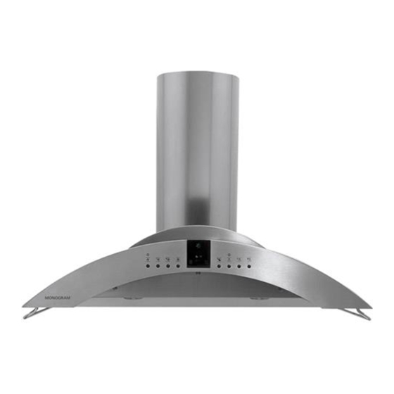
GE Monogram ZV850 Installation Instructions Manual
36" island vent hood
Hide thumbs
Also See for Monogram ZV850:
- Installation instructions manual (16 pages) ,
- Owner's manual (12 pages) ,
- Technical service manual (30 pages)
Advertisement
Quick Links
Advertisement

Summary of Contents for GE Monogram ZV850
- Page 1 GE Monogram ® Installation Instructions 36" Island Vent Hood Model ZV850 Monogram°...
- Page 2 Product failure due to improper installation is not covered under the GE Sufficient air is needed for proper combustion Appliance _¥arranty. See the Owner's and exhausting of gases through the flue Manual for warranty information.
- Page 3 36" Island Vent Hood Model Model This vent hood is designed to NOTE: Accessories to meet proper ZV850 be used in vented ceiling mounted ceiling height are required to complete Available installations. the installation. ZX858 - Fox 8 ft. ceiling height.
- Page 4 Cover Accessories correct Duct Cover Accessory for 8 ft. to 10 ft. ceilings that must be ordered with the hood. ZV850SBInstallation Heights ZV850 Duct Cover Dimensions 9-7/16" . Vented Actual Installation Duct Cover Ceiling * PossibleHood Height Installation Height Accessory ZX858SB 14-3/16"...
- Page 5 Installation Preparation 36" Island Vent Hood 7bols and • Tapemeasure • 120V60Hz. 15 or 20 Amp, 2 wire with ground. • Knife Properly grounded branchcircuit. Materials • Spirit level • Strain relief for junction box cover. • Wire cutter • Plumb Required •...
- Page 6 33 ft. Total Duct Run __ _Actual length of straight duct plus duct fitting equivalent. Equivalent length of duct pieces are based on actual tests conducted by GE Evaluation Engineering and reflect requirements for good venting performance with any ventilation hood.
- Page 7 Installation Preparation 36" Island Vent Hood Plan the location Ceiling Determine the exact location of the vent hood. Hood • Use a plumb to check location to be sure :..]z D_ttinllne countertop/cooktop location below the hood Advance will align exacdy. •...
- Page 8 Installation Preparation 36" Island Vent Hood Cross Framing • Arrange cross flatning in tile ceiling to suit tile existing structure. See examples. - Secure each 2 x 4 block with at least four (4), #10 wood screws, 3" long (minimum size Advance screws, not supplied).
- Page 9 Installation 36" Islan, d Vent Hood The vent hood is packed separately flom the required accessory ZX858, ZX859 or ZX8510. • Remove the flame, cove_; parts box, side bars and packaging. Remove • Remove junction box cover. • Install suain relief onto junction box coveL Paekacin¢...
- Page 10 Installation 36" Island Vent Hood • Align the template with the marks on the ceiling and tape in place. - Be sure the template is oriented correctly, with the fiont of the hood. • Use a plumb to be sure the mounting holes Template will provide parallel alignment...
- Page 11 Installation 36" Island Vent Hood Wiring Ce!ling • Route house Mring through the ceiling hole and pull a length to reach the hood junction Front Side box, approximately 6" below the support. • Tape the wire to the flont of the flame support to prevent damage during Support...
- Page 12 Installation 36" Island Vent Hood S e 8 TopDuct Dover Install Screwon EachSide Pretap 2 Screw / Install Holes Bottom Duct Cover BottomDuct Decorative TopDuct Cover Cover Duct Covers Top Duct Cover --\\\ ,,,(Stop Screw o X..Install Stop Screw in One of 3 Holes •...
- Page 13 Installation 36" Island Vent Hood Bottom Align Duct Connector t o .. / Align gU?tr HouseDuct Mounting Studs StopScrew __ Install --l /4,ock Install H II[ot _ --1 J washer Hood • 4 Nuts • Check hood level in both directions.
- Page 14 Installation 36" Island Vent Hood Slide Duct Cover Down, Install Side Utility Bars • Hold the deco_afive duct cove_ and • Install the side utility ba_s with screws _emove the tempora_y stop sc_ew. Retmn as shown. the sctew to the seevice manual envelope foi fllttl_e use.
- Page 15 Installation 36" Island Vent Hood Install LowerFilter Filters Slots • Remove protective film on filters. • Tip the filter into the lower slots at the rear of the opening. I,ift the filter and pull the knob forward until the filter rests on the slots.
- Page 16 General Electric. There[k_re, materials, appearance specifications s/ll_ject to change witho/lt notice. GEConsumer & Industrial Pub. No. 49-8970-2 GEAppliances 04/07.]R General E lectric Company Printed in halv Louisville, K Y40225 monogram, !)43!)6398 5")2007 GE Company...


