Table of Contents
Advertisement
Advertisement
Table of Contents

Related Manuals for Asus P4SD-LA Yale


Summary of Contents for Asus P4SD-LA Yale
- Page 1 P4SD-LA (Yale) User Guide...
-
Page 2: Table Of Contents
Contents P4SD-LA specifications summary ..........iii Motherboard layout ............... 1 Central Processing Unit (CPU) ..........2 System memory ..............3 Memory configurations ............3 Installing a DIMM ..............4 Expansion slots ..............5 Standard interrupt assignments ..........5 IRQ assignments for this motherboard ........5 PCI slots ................ -
Page 3: P4Sd-La Specifications Summary
P4SD-LA (Yale) specifications summary ® ® Socket 478 for Intel Pentium 4 Northwood/Prescott New power design to support up to 3.2+GHz processors On-die 512KB/256KB L2 cache with full speed Supports Intel ® Hyper-Threading technology ® Chipset Intel Springdale PE MCH ®... - Page 4 P4SD-LA (Yale) specifications summary BIOS features 4Mb Flash EEPROM, AMI BIOS with enhanced ACPI, PnP, DMI2.0, Green features Industry standard PCI 2.2, USB 2.0 WfM 2.0. DMI 2.0, WOL/WOR by PME Manageability Micro-ATX form factor: 9.6 in x 9.6 in (24.5 cm x 24.5 cm)
-
Page 5: Motherboard Layout
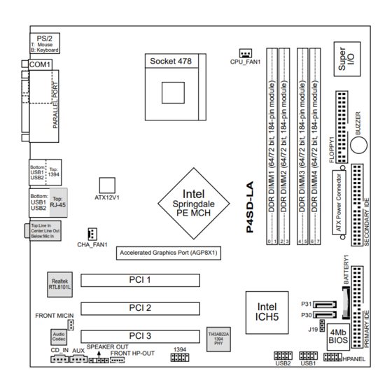
Center:Line Out Below:Mic In CHA_FAN1 Accelerated Graphics Port (AGP8X1) PCI 1 Realtek RTL8101L Intel PCI 2 ICH5 FRONT MICIN PCI 3 Audio TI43AB22A Codec 1394 BIOS SPEAKER OUT CD_IN AUX 1394 FRONT HP-OUT HPANEL USB2 USB1 ASUS P4SD-LA (Yale) motherboard... -
Page 6: Central Processing Unit (Cpu)
CPU. The lever clicks on the side tab to indicate that it is locked. 6. Install a CPU heatsink and fan following the instructions that came with the heatsink package. 7. Connect the CPU fan cable to the CPU_FAN1 connector on the motherboard. ASUS P4SD-LA (Yale) motherboard... -
Page 7: System Memory
Bus). Refer to Table 2 below. 4. Double-sided 16-bit DDR DIMMs are not supported on this motherboard. 5. It is not recommended to create a three-DIMM configuration in dual- channel mode. The third DIMM is ignored in the dual-channel operation. ASUS P4SD-LA (Yale) motherboard... -
Page 8: Installing A Dimm
DIMM matches the break on the socket. 3. Firmly insert the DIMM into the socket until the retaining clips snap back in place and the DIMM is properly seated. Unlocked Retaining Clip ASUS P4SD-LA (Yale) motherboard... -
Page 9: Expansion Slots
— — — — shared Onboard LAN — — — shared — — — — Onboard audio — used — — — — — — Onboard 1394 controller — — — — — shared — — ASUS P4SD-LA (Yale) motherboard... -
Page 10: Pci Slots
Note the notches on the card golden fingers to ensure that they fit the AGP slot on your motherboard. Install only +0.8V/+1.5V AGP cards on this motherboard! AGP Card without Retention Notch P4SD-LA Accelerated Graphics Port (AGP8X) ASUS P4SD-LA (Yale) motherboard... -
Page 11: Jumper
4. Hold down the <Del> key during the boot process and enter BIOS setup to re-enter data. Except when clearing the RTC RAM, never remove the cap on jumper J19 default position. Removing the cap will cause system boot failure! Clear CMOS Normal P4SD-LA Clear RTC RAM (Default) ASUS P4SD-LA (Yale) motherboard... -
Page 12: Connectors
PIN 1 PIN 1 P4SD-LA Floppy Disk Drive Connector 2. ATX power connectors (20-pin ATX_POWER1, 4-pin ATX12V) These connectors connect to an ATX 12V power supply. The plugs from the power supply are designed to fit these connectors in only one orientation. Find the proper orientation and push down firmly until the connectors completely fit. - Page 13 2. The hole near the blue connector on the UltraDMA100/66 cable is intentional. NOTE: Orient the red markings (usually zigzag) on the IDE ribbon cable to PIN 1. PIN 1 P4SD-LA IDE Connectors PIN 1 ASUS P4SD-LA (Yale) motherboard...
- Page 14 1394 module. Attach the 10-1 pin cable plug to this connector, and the 6-pin cable plug to the 1394 module. You may also connect a 1394-compliant internal hard disk to this connector. 1394 P4SD-LA IEEE 1394 Connectors ASUS P4SD-LA (Yale) motherboard...
- Page 15 The USB module is purchased separately. USB2 USB1 P4SD-LA USB 2.0 Header 7. Speaker out connector (5-1 pin SPEAKER OUT) This connector is for an optional audio module. Connect one end of the audio cable to this connector and the other end to the audio module.
- Page 16 FRONT MICIN MIC Power MIC Input Ground P4SD-LA Front Microphone Connector 10. Internal audio connectors (4-pin CD-IN, AUX) These connectors allow you to receive stereo audio input from sound sources such as a CD-ROM, TV tuner, or MPEG card. CD-IN (Black)
- Page 17 Switch* HPANEL HDLED Reset SW P4SD-LA Front Panel Connector • System Power LED Lead (3-1 pin PLED) This 3-1 pin connector connects to the system power LED. The LED lights up when you turn on the system power, and blinks when the system is in sleep mode.
- Page 18 ASUS P4SD-LA (Yale) motherboard...