Table of Contents
Advertisement
Advertisement
Table of Contents

Related Manuals for JL Audio e110


Summary of Contents for JL Audio e110
- Page 1 Owner’s Manual e110 e112...
-
Page 2: Important Safety Instructions
9) Power Cord Protection — Power-supply cords should be routed so that they are not likely to be walked on or pinched by items placed upon or against them, paying particular attention to cords at plugs, convenience receptacles, and the point where they exit the subwoofer. Page 2 | e110 & e112... - Page 3 THIS SUBWOOFER IS CAPABLE OF PRODUCING VERY HIGH SOUND PRESSURE LEVELS. PLEASE EXERCISE RESTRAINT IN ITS OPERATION TO WARNING PROTECT YOUR HEARING FROM PERMANENT DAMAGE. | e110 & e112 Page 3...
-
Page 4: Table Of Contents
Specifi cations: ............32 INTRODUCTION Congratulations on your purchase of a JL Audio E-Sub powered subwoofer system. Th is product has been critically engineered to deliver exceptional performance in your home theater or audio system for many years to come. -
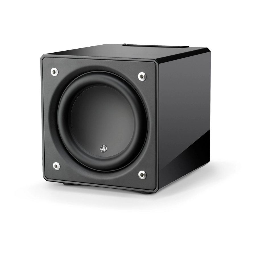
Page 5: Product Overview
Th e E-Sub drivers off er peak-to-peak excursion capabilities well in excess of 2.5 inches (64 mm - e110), and 3 inches (76 mm - e112) to comfortably handle the dynamics of the most demanding program material. -
Page 6: Placing Your E-Sub In Your Listening Room
Increasing the distance between the subwoofer and the walls may help to smooth upper bass response in some rooms. We recommend that you avoid placing the E-Sub near windows to prevent rattling and sound transmission to the outside world. Page 6 | e110 & e112... - Page 7 Recommended Floor Placement Options for One E-Sub | e110 & e112 Page 7...
- Page 8 INPUTS OUTPUTS HIGH LEVEL INPUTS imported components the e112, and AT LEAST 60 square inches (386 sq.cm.) for the e110. VENT VENT Th ese areas are equal to the woofer cone area for each model and will ensure that the E-Sub’s output is not choked by the custom cabinet.
- Page 9 – the benefi ts can be substantial. High-resolution measurements and professional system calibration are recommended for the best possible results & system performance. | e110 & e112 Page 9...
- Page 10 – the benefi ts can be substantial. High-resolution measurements and professional system calibration are recommended for the best possible results & system performance. Recommended Subwoofer Placement Options for Four E-Subs Page 10 | e110 & e112...
-
Page 11: Unpacking Your E-Sub
11. Lift the subwoofer off the remaining styrofoam cap and place this cap in the carton. 12. Remove the protective cloth cover and place in the carton. IMPORTANT! PLEASE RETAIN ALL PACKAGING FOR SAFE TRANSPORTATION IMPORTANT OF THE SUBWOOFER AND FOR ANY FUTURE SERVICE NEEDS. | e110 & e112 Page 11... -
Page 12: Top-Mounted Control Panel Layout
Top-Mounted Control Panel Th e labeled Figure below depicts the top-mounted control panel of the E-Sub subwoofer. Th e E110 and E112 have identical layouts. Power Crossover Switch phase (deg.) page 14 page 15 page 16 Master Level Crossover Polarity page 14 freq. -
Page 13: Rear Connection Panel Layout
Rear Connection Panel (120V Model Shown) Th e labeled Figure below depicts the rear panel of the E-Sub subwoofer. Th e e110 and e112 have identical layouts. Warranty void if serial number is removed, altered or defaced. CH. 2 CH. 1... -
Page 14: Top-Mounted Controls In Detail
When rotated fully counter clockwise, the E-Sub’s output will be fully muted. When at the “0” or straight up position, the level is at reference gain. When turned fully clockwise, the E-Sub’s level is at its maximum sensitivity (loudest). Page 14 | e110 & e112... - Page 15 “phase (deg.)” control. Either position of the “Polarity” switch may provide a smoother transition between your E-Sub and the satellite speakers. Use source material with good mid and upper bass content for evaluation. | e110 & e112 Page 15...
- Page 16 “phase (deg.)” control and listen for better defi ned mid- bass and a smoother transition between the subwoofer and satellite speaker systems. If no single setting sounds better than another, leave the “phase (deg.)” control at 0 degrees. Page 16 | e110 & e112...
-
Page 17: Connecting Your E-Sub(S)
Connections are as follows: “High Level Input” Connector (from left to right): 1: Right Channel Negative 2: Right Channel Positive 3: Left Channel Negative 4: Left Channel Positive Input Impedance: 4.3 kΩ | e110 & e112 Page 17... - Page 18 If too many components are connected with an E-Sub subwoofer to one electrical outlet, you risk tripping a household circuit breaker during very demanding program material. If this happens, split the E-Sub and other components between two AC electrical circuits. Page 18 | e110 & e112...
- Page 19 “Off ” position. Isolated LINE LINE HIGH LEVEL INPUTS INPUTS OUTPUTS E-SUB REAR PANEL WARNING! TURN OFF THE E-SUB(S) AND ALL OTHER EQUIPMENT IN THE WARNING SYSTEM BEFORE MAKING OR CHANGING ANY CONNECTIONS! | e110 & e112 Page 19...
- Page 20 E-Subs. Refer to the manual of your receiver/pre-pro for details. WARNING! TURN OFF THE E-SUB(S) AND ALL OTHER EQUIPMENT IN THE WARNING SYSTEM BEFORE MAKING OR CHANGING ANY CONNECTIONS! Page 20 | e110 & e112...
- Page 21 RCA-type connectors to make these connections. SPEAKER OUTPUTS – – INPUTS SATELLITE AMPLIFIER TO SATELLITE SPEAKERS WARNING! TURN OFF THE E-SUB(S) AND ALL OTHER EQUIPMENT IN THE WARNING SYSTEM BEFORE MAKING OR CHANGING ANY CONNECTIONS! | e110 & e112 Page 21...
- Page 22 Output” to the right input of your satellite amplifi er. Use good-quality audio interconnect cables with RCA-type connectors to make these connections. WARNING! TURN OFF THE E-SUB(S) AND ALL OTHER EQUIPMENT IN THE WARNING SYSTEM BEFORE MAKING OR CHANGING ANY CONNECTIONS! Page 22 | e110 & e112...
- Page 23 Isolated E-SUB TOP CONTROL PANEL LINE LINE HIGH LEVEL INPUTS INPUTS OUTPUTS E-SUB REAR CONTROLS WARNING! TURN OFF THE E-SUB(S) AND ALL OTHER EQUIPMENT IN THE WARNING SYSTEM BEFORE MAKING OR CHANGING ANY CONNECTIONS! | e110 & e112 Page 23...
-
Page 24: Recommended Setup Procedure
1. Crossover Filter Frequency Select a low-pass fi lter frequency of 80 Hz (24dB/octave slope, if given an option) 2. Subwoofer Output Level Set the subwoofer output level to “0” or its middle position. Page 24 | e110 & e112... - Page 25 “Crossover Freq. (Hz)” knob to the “80 Hz” position. 3. “Polarity” Switch Flip the “Polarity” switch to “0”. 4. “phase (deg.)” Knob Rotate the “phase (deg.)” knob to “0” degrees | e110 & e112 Page 25...
-
Page 26: Recommended Setup Procedure
Th is completes the basic setup process! You can achieve further improvements through the correct use of processing built into your receiver or preamp/processor. Consult with your JL Audio authorized retailer if you require further setup assistance. IMPORTANT! WRITE DOWN ALL SETTINGS PERFORMED IN STEPS 1-3 FOR IMPORTANT FUTURE REFERENCE. -
Page 27: Frequently Asked Questions
Is it safe to use my E-Sub outdoors, in a sauna or on a pool deck? NO. Th e E-Sub is only designed for operation in dry, indoor environments. | e110 & e112 Page 27... -
Page 28: Cleaning Your E-Sub
E-Sub. Never use solvents or aggressive cleaning agents on your E-Sub. When in doubt, test the cleaning product on the underside of the cabinet and let it sit for several days before committing to its use on visible portions of the cabinet. Page 28 | e110 & e112... -
Page 29: Troubleshooting
3. If your other speakers play, but the E-Sub does not, try changing the cable that connects the E-Sub to the system. 4. If the problem persists, call your dealer or JL Audio Technical Support for assistance. Th e bass level has changed. - Page 30 INSTALLATION NOTES Page 30 | e110 & e112...
-
Page 31: Limited Warranty / Service Information
JL Audio for service. Cosmetic damage due to accident or normal wear and tear is not covered under warranty. -
Page 32: Specifications
HOME AUDIO | MOBILE AUDIO | MARINE AUDIO | POWERSPORTS “JL Audio”, “E-Sub” and the JL Audio logo are registered trademarks of JL Audio, Inc., “Ahead of the Curve” is a trademark of JL Audio, Inc. Due to continuous product development, all specifications are subject to change without notice.