
Related Manuals for Fujitsu Siemens Computers D1534


Summary of Contents for Fujitsu Siemens Computers D1534
- Page 1 Technisches Handbuch / Technical Manual Mainboard D1534 RiserCard E383 Deutsch / English...
- Page 2 Please contact: • your sales partner • your sales outlet You will find further information in the manuals "Safety" and "Warranty". The latest information and updates (e. g. BIOS update) on our mainboards can be found on the Internet under: http://www.fujitsu-siemens.com/mainboards...
- Page 4 Questo manuale è stato stampato su carta da riciclaggio. Denna handbok är tryckt på recyclingpapper. Dit handboek werd op recycling-papier gedrukt. Herausgegeben von/Published by Fujitsu Siemens Computers GmbH A26361-D1534-Z120-1-7419 Bestell-Nr./Order No.: Printed in the Federal Republic of Germany AG 0503...
- Page 5 Deutsch English Mainboard D1534 Technisches Handbuch Technical Manual Ausgabe Mai 2003 May 2003 edition...
- Page 6 Alle weiteren genannten Warenzeichen sind Warenzeichen oder eingetragene Warenzeichen der jeweiligen Inhaber und werden als geschützt anerkannt. Copyright Fujitsu Siemens Computers GmbH 2003 Alle Rechte vorbehalten, insbesondere (auch auszugsweise) die der Übersetzung, des Nachdrucks, der Wiedergabe durch Kopieren oder ähnliche Verfahren.
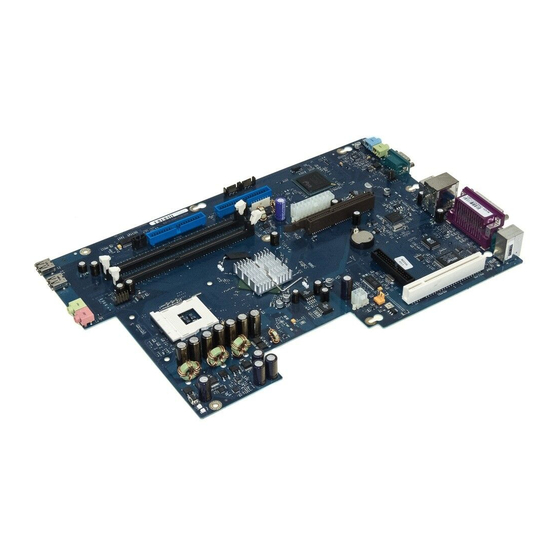
- Page 7 Übersicht/Overview Mainboard D1534 Interne Anschlüsse und Steckplätze / Internal Mainboard connectors and slots PCI-Baugruppensteckplatz für Riser E383 / PCI riser slot for Riser E383 Diskettenlaufwerk / Floppy disk drive Lüfter 1 / Fan 1 Stromversorgung +12 V ( Power supply +12 V...
-
Page 9: Table Of Contents
Contents Übersicht/Overview Mainboard D1534 Mainboard D1534 ..........................1 Notational conventions ......................1 Important notes..........................2 Information about boards ......................2 List of features...........................3 Special technical features - special features ................4 Interfaces and connectors ......................6 External ports ............................6 Internal ports and connectors ......................7 Hard disk connection .........................7 Pin assignment of internal ports......................8... -
Page 11: Mainboard D1534
Mainboard D1534 Your mainboard is available in different configuration levels. Depending on the configuration chosen, some of the hardware components described may not be available on your mainboard. Additional information Information on the BIOS Setup and additional descriptions of the drivers are contained: •... -
Page 12: Important Notes
Mainboard D1534 Important notes With the mainboard installed you must open the system to access the mainboard. How to dismantle and reassemble the system is described in the operating manual accompanying the system. Connecting cables for peripherals must be adequately shielded to avoid interference. -
Page 13: List Of Features
Gigabit LAN / with Alert-on-LAN HI-SPEED USB 2.0 SmartCard Reader Support (USB / serial) Temperature monitoring System Monitoring Fujitsu Siemens Computers Keyboard Power Button Support Internal ports DIMM Sockets (DDR SDRAM, PC2100/2700/3200) 1 per channel AGP Slot (2/4/8x, 32 bit, 66 MHz, 1.5 V) PCI slot (32 bit, 33 MHz, 5 V and 3.3 V) -
Page 14: Special Technical Features - Special Features
Thermal Management and System Monitoring A microcontroller developed by Fujitsu Siemens Computers reliably protects your PC against damage caused by overheating. Overheating can lead to the data loss or processor damage. - Page 15 If an error occurs during a BIOS update (e.g. due to a power failure), the system BIOS will be destroyed. All Fujitsu Siemens Computers mainboards are equipped with a recovery BIOS. With it a destroyed BIOS can easily be restored. Exact instructions are provided in the chapter "BIOS Recovery - Recovering System BIOS".
-
Page 16: Interfaces And Connectors
The LAN RJ45 connector has two LEDs (light emitting diodes). 1 = a connection exists (e.g. to a hub). 2 = Link Mode: the LAN connection is active. WOL mode: a Magic Packet is being received. 6 - English A26361-D1534-Z120-2-7419... -
Page 17: Internal Ports And Connectors
Connect the end of the cable marked with blue to the mainboard. If you have connected one or two hard disks to a serial ATA (one hard disk is possible per serial ATA connection), you must configure the respective settings in the BIOS Setup. English - 7 A26361-D1534-Z120-2-7419... -
Page 18: Pin Assignment Of Internal Ports
(system fan - supervised) Signal Controlled Fan voltage (0 V, +6 V ... +12 V, max. 1 A) or fix Fan voltage (+12 V, max. 1 A) Fan sense Processor power supply power supply Signal Signal +12V +12V 8 - English A26361-D1534-Z120-2-7419... - Page 19 +5 V (VCC) USB C/D - dual channel (internal or external via special wire) Signal Signal Chipcardreader on VCC C VCC D Data negative C Data negative D Data positive C Data positive D not connected English - 9 A26361-D1534-Z120-2-7419...
- Page 20 CD GND Right CD audio input Power control (system monitoring) Signal AC Outlet (high asserted) PS FAN Control (PS FAN C max. 3 mA) Reserved PS FAN Sense SMB CLK SMB DATA VCC EEPROM (+3.3 V) 10 - English A26361-D1534-Z120-2-7419...
- Page 21 Interfaces and connectors Serial ATA (internal) Signal Signal Transmit data positive Transmit data negative Receive data negative Receive data positive Audio S/PDIF (3-pin) Signal SPDIF out English - 11 A26361-D1534-Z120-2-7419...
-
Page 22: Jumper Settings
BIOS you need a Flash BIOS Diskette (see "BIOS update" chapter). The System BIOS executes from floppy drive A: and the inserted "Flash-BIOS- Diskette" restores the System BIOS on the mainboard. Normal operation (default setting). 12 - English A26361-D1534-Z120-2-7419... -
Page 23: Add-On Modules / Upgrading
(A) with regard to the position (4). The angled corner of the processor can also be at a different location than shown in the illustration. Ê Push the lever back down until it clicks into place (5). English - 13 A26361-D1534-Z120-2-7419... -
Page 24: Mounting Heat Sink
Depending on the processor variant, clips may also be supplied for mounting the heat sink that fix it in place. Ê When you have mounted the optional fan, connect the fan plug to the corresponding connection on the mainboard. 14 - English A26361-D1534-Z120-2-7419... -
Page 25: Upgrading Main Memory
64, 128, 256, 512 or 1024 Mbyte for one module A current list of the memory modules recommended for this mainboard is available on the Internet at: www.fujitsu-siemens.com. At least one memory module must be installed. Memory modules with different memory capacities can be combined. -
Page 26: Upgrading Agp Screen Controllers
PCI IRQ Lines connect AGP slots, PCI slots and onboard components to the interrupt controller. PCI IRQ Lines are permanently wired on the mainboard. Which ISA IRQs are assigned to the PCI IRQ Lines is normally automatically specified by the BIOS (see description in "BIOS Setup"). 16 - English A26361-D1534-Z120-2-7419... - Page 27 PCI slot with IRQ sharing, check whether the expansion card properly supports IRQ sharing with the other devices on this PCI IRQ Line. The drivers of all cards and components on this PCI IRQ Line must also support IRQ sharing. English - 17 A26361-D1534-Z120-2-7419...
-
Page 28: Replacing The Lithium Battery
Press the locking lug in the direction of the arrow; the battery jumps somewhat out of the holder (1). Ê Remove the battery (2). Ê Insert a new lithium battery of the same type into the socket (3). 18 - English A26361-D1534-Z120-2-7419... -
Page 29: Bios Update
Add-on modules / Upgrading BIOS update When should a BIOS update be carried out? Fujitsu Siemens Computers makes new BIOS versions available to ensure compatibility to new operating systems, new software or new hardware. In addition, new BIOS functions can also be integrated. -
Page 30: Bios Recovery - Recovering System Bios
To guarantee the best possible performance and error-free operation, Intel recommends updating the microcode regularly. Intel refers to the use of the processor without regular microcode updates as operation outside the specifications. 20 - English A26361-D1534-Z120-2-7419... -
Page 31: Drivers
Add-on modules / Upgrading Safety for processor on Fujitsu Siemens Computers mainboards If the processor uses an old or incorrect microcode, error-free operation cannot be ensured. Fujitsu Siemens Computers has therefore implemented a function on its mainboards that interrupts the booting process if no suitable microcode is available for the installed processor. -
Page 32: Error Messages
Available CPUs do not support the same bus frequency – System halted! Memory type mixing detected Non Fujitsu Siemens Memory Module detected – Warranty void There are more than 32 32 RDRAM devices in the system Check whether the system configuration has changed. If necessary, correct the settings. - Page 33 Keyboard error Check that the keyboard is connected properly. Keyboard error nn nn Stuck Key Release the key on the keyboard (nn is the hexadecimal code for the key). English - 23 A26361-D1534-Z120-2-7419...
- Page 34 = Group number x = Number of SEs found on the communication bus y = Number of SEs entered in Number of connected SE k1, k2 ... = Device ID of the storage extensions found 24 - English A26361-D1534-Z120-2-7419...
-
Page 35: Dos Error Messages
Critical error logged to server management processor - system halted If the NMI button of the control panel is pressed, then the following error text is output on the screen: Frontpanel NMI activated - system halted English - 25 A26361-D1534-Z120-2-7419... -
Page 36: Smartcard Reader - Error Messages
You have exceeded the maximum number of failed attempts to enter the PIN. The Sicrypt SmartCard is blocked. Enter the administrator PIN to re-activate the Sicrypt SmartCard. You must then enter a new User PIN to restart the system. 26 - English A26361-D1534-Z120-2-7419... -
Page 37: Glossary
Universal Serial Bus GMCH Graphics and Memory Controller Video Graphic Adapter Graphics Performance Wake On LAN Accelerator Inter Integrated Circuit IAPC Instantly Available Power Managed Desktop PC Design I/O Controller Hub Intelligent Drive Electronics IPSEC Internet Protocol Security English - 27 A26361-D1534-Z120-2-7419...