Table of Contents
Advertisement
Advertisement
Table of Contents

Related Manuals for Grizzly G1033


Summary of Contents for Grizzly G1033
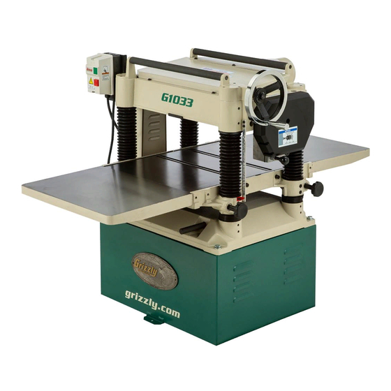
- Page 1 20'' PLANER MODEL G1033 INSTRUCTION MANUAL COPYRIGHT © 1990 BY GRIZZLY INDUSTRIAL, INC. WARNING: NO PORTION OF THIS MANUAL MAY BE REPRODUCED IN ANY SHAPE OR FORM WITHOUT THE WRITTEN APPROVAL OF GRIZZLY INDUSTRIAL, INC. REVISED APRIL, 1999. PRINTED IN U.S.A.
-
Page 3: Table Of Contents
GENERAL ...23 KNIVES ...23 LUBRICATION...24 BELT TENSION ...25 BELT ALIGNMENT ...25 CLOSURE MACHINE DATA ...27 TROUBLESHOOTING...28 PARTS BREAKDOWN AND PARTS LISTS ...29-35 ADJUSTMENT BLOCK PATTERN ...36 WIRING DIAGRAM ...37 WARRANTY AND RETURNS ...38 G1033 20" Planer Table Of Contents PAGE... -
Page 4: Safety
G1033 20" Planer VISITORS... - Page 5 12. SECURE WORK. Use clamps or a vise to hold work when practical. It’s safer than using your hand and frees both hands to operate tool. G1033 20" Planer 13. DON’T OVERREACH. Keep proper foot- 14. MAINTAIN TOOLS WITH CARE. Keep 15. DISCONNECT TOOLS before servicing 16.
-
Page 6: Additional Safety Instructions For Planers
Ensure that the planer is properly adjusted before using. Like all power tools, there is danger asso- ciated with the Model G1033 20" Planer. Accidents are frequently caused by lack of familiarity or failure to pay attention. Use this tool with respect and caution to lessen the possibility of operator injury. -
Page 7: Circuit Requirements
SECTION 2: CIRCUIT REQUIREMENTS 220V Operation The 3 HP G1033 Planer motor is wired to oper- ate at 220V only. A 220V plug that matches your 220V receptacle must attach to the end of the power cord. Plugs and receptacles can be pur- chased at your local hardware store or home center. -
Page 8: Introduction Commentary
SECTION 3: INTRODUCTION Commentary We are proud to offer the Grizzly Model G1033 20" Planer. The Model G1033 is part of a growing Grizzly family of fine woodworking machinery. When used according to the guidelines set forth in this manual, you can expect years of trouble- free, enjoyable operation and proof of Grizzly’s... -
Page 9: Unpacking
If you need advice regarding this situation, please call us immediately. The Model G1033 is a heavy machine (770 lbs. shipping weight). DO NOT over-exert yourself while unpacking or moving your machine –... -
Page 10: Clean Up
FLOOR LOAD Your G1033 Planer represents a large weight load in a small footprint. Most commercial floors are suitable for the Model G1033. Some residen- tial floors may require additional build up to sup- port both machine and operator. WORKING CLEARANCES... -
Page 11: Assembly
SECTION 4: ASSEMBLY Overview Most of your G1033 Planer has been assembled at the factory, but some parts must be assembled or installed after delivery. We have organized the assembly process into steps. Please follow along in the order presented here. -
Page 12: Dust Hood
Dust Hood The G1033 features a dust hood with a 5'' dust port. It is only to be used in conjunction with a dust collection system. Install the dust hood as follows: 1. Match the mounting holes on the dust hood with the tapped holes on the outfeed end of the cutterhead casting. -
Page 13: Knife Setting Jig
Planer knives are dangerously sharp. Use extreme caution when working near cutting surfaces. Failure to exercise care while working near knives could result in severe injury. G1033 20" Planer Figure 6. Knife setting jig. NOTES Jig Rod E-clip Jig Bracket... -
Page 14: Adjustments Chain Adjustment
SECTION 5: ADJUSTMENTS Chain Adjustment The chain drive in the Model G1033 transfers movement from the hand wheel driven column to the three other support columns. The chain drive may require adjustment to remove slack as the chain stretches over time, or as part of table lev- eling procedures. -
Page 15: Chain Drive
5. If the table is too high at the right side, rotate the sprockets in the opposite direc- tion. G1033 20" Planer Figure 9. Using block to align cutterhead. When you get the tolerance to within the .016'' range, micro-adjust by loosening the Allen head... -
Page 16: Bed Rollers
5. Spin the rollers and inspect for free move- ment. Planer knives are dangerously sharp. Use extreme caution when working near cutting surfaces. Failure to exercise care while working near knives could result in severe injury. G1033 20" Planer... -
Page 17: Knife Inspection
Knife Inspection The G1033 20" Planer comes equipped with a 4- knife cutterhead. The knives must be periodically replaced or adjusted. Adjustments should be as precise as possible with tolerances within ±.001'' to prolong the sharpness of the knife edges. -
Page 18: Feed Roller Speed
See Figure 6. The table is now positioned correctly. Lock the table in place. 7. Remove the feeler gauge and move the block to the right end of the infeed drive roller. G1033 20" Planer... -
Page 19: Spring Tension
See Figure 18. Figure 18. Adjusting roller height. G1033 20" Planer 11. Follow the same procedure at the other end of the infeed roller and on both sides of the outfeed roller. -
Page 20: Chipbreaker
Like the chip- breaker, the pressure bar can be adjusted with one setscrew. Make sure to adjust the second setscrew to match the one you’ve just adjusted. 4. Tighten the lock nut in place. G1033 20" Planer... -
Page 21: Chip Deflector
When using a dust collector, it may be nec- essary to increase the distance from the cutterhead/knives to the deflector to aid in chip removal. G1033 20" Planer Static Chain Adjuster Once the rollers, chip breaker and pressure bar are properly adjusted, you will need to reset the static chain tensioner. -
Page 22: Scale Adjustment
See Figure Figure 23. Cutterhead height scale. -20- Anti-Kickback Fingers The Model G1033 provides an anti-kickback sys- tem as a safety feature. The anti-kickback fingers hang from a rod suspended across the cutter- head casting. The anti-kickback fingers should be inspected regularly. -
Page 23: Operations
Be certain the safety glasses you wear meet the appropriate standards of the American National Standards Institute (ANSI). G1033 20" Planer Operational Tips 1. Inspect lumber for defects, warping, cupping, twisting, and for foreign objects (nails, sta- ples, imbedded gravel, etc,). If you have any question about the quality of your lumber, do not use it. -
Page 24: Wood Characteristics
Using a dust collection system in combination with the planer can help reduce chip marks. Inspect the chip deflector and readjust (as described earlier in the text). G1033 20" Planer... -
Page 25: Maintenance
This planer has knives with a grind angle of 45˚ which is a configuration which should suit most general planing needs. The optimal grind or bevel... -
Page 26: Lubrication
Bearings are standard sizes and can be replaced through Grizzly. Proper lubrication of other components of the Model G1033 are essential for long life and trou- ble-free operation. Below is a list of components that require periodic lubrication. Schedules are based on daily use. -
Page 27: Belt Tension
See Figure 27. Establish a periodic schedule of inspection. Check for wear, cracking, nicks, or glazing. Replace belts immediately if you spot any signs of deterioration. Always use three belts when operating the Model G1033. Figure 27. Adjustments for belt tension. G1033 20" Planer Belt Alignment Proper belt alignment prevents premature belt wear. -
Page 28: Closure
Washington location using the address in the Introduction. The specifications, drawings, and photographs illustrated in this manual represent the Model G1033 as supplied when the manual was prepared. However, due to Grizzly’s policy of continuous improvement, changes may be made at any time with no obligation on the part of Grizzly. -
Page 29: Machine Data
Customer Service #: (570) 326-3806 • To Order Call: (800) 523-4777 • Fax #: (800) 438-5901 GRIZZLY MODEL G1033 20" PLANER Design Type ... Floor Model Overall Dimensions: Table Size ...25 Height ...41" Overall Depth ...39" Overall Width ...58" Shipping Weight ...770 lbs. -
Page 30: Troubleshooting
TROUBLESHOOTING This section covers the most common processing problems encountered in planing and what to do about them. Do not make any adjustments until planer is unplugged and moving parts have come to a complete stop. SYMPTOM POSSIBLE CAUSE Motor will not start. - Page 32 CHAIN 33 LINKS P1071075 STRAIN RELIEF P1033093 POWER CORD P1033094 STAR WASHER #10 PSB04M CAP SCREW M6-1.0X10 PSS14M SETSCREW M8-1.25X12 P1033097 RETAINER P1033098 COLLAR PLW03M LOCK WASHER 6MM PS09M PHLP HD SCR M5-0.8X10 PSW01-1 PLASTIC SCREW G1033 20" Planer " "...
- Page 33 BEARING 6201 P1033204 ECCENTRIC SHAFT PSS04M SETSCREW M6-1.0X12 P1021143 THREADED GIB P1033207 LOCK ROD P1021146 P1021145 KNOB G1033 20" Planer PART # DESCRIPTION PSB14M CAP SCREW M10-1.25X20 P1033211 EXT ROLLER BAR P1033212 EXTENSION ROLLER PB32M HEX BOLT M10-1.5X25 PW04M FLAT WASHER 10MM...
- Page 34 REF PART # DESCRIPTION P1033301 BASE PSS13M SETSCREW M10-1.5 X 12 P1033303 COLUMN P1033304 COLUMN P1033305 LEADSCREW P1033306 LEADSCREW P1033307 LEADSCREW NUT P1033308 BUSHING PR22M INT RETAINING RING 38MM PK10M KEY 5 X5 X 12 P1033311 GEAR PR03M SNAP RING 12MM P6202 BALL BEARING 6202 PR21M...
- Page 35 PART # DESCRIPTION P1033401 STAND P1033402 COVER PFH06M FLAT HD SCREW M6-1.0 X 20 P1033404 P1033405 MOTOR MOUNT PSS20M SETSCREW M8-1.25 X 8 P1033407 COLLAR P1033408 ADJUSTABLE BOLT PN09M HEX NUT M12-1.75 PW01 FLAT WASHER PB07M HEX BOLT M8-1.25 X 25 P1033412 WASHER ⁄...
- Page 36 KEY 5 X 5 X 23 CHAIN, 25 LINKS HEX BOLT M6-1.0 X 15 SHIFTER SHIFTING SHAFT HANDLE FLAT WASHER 6MM HEX BOLT M6-1.0X12 O-RING 12MM KNOB GASKET GEAR CASE CAP SCREW M6-1.0X25 OIL PLUG CAP SCREW M8-1.25X50 G1033 20" Planer...
- Page 37 P1021149 SPROCKET PRP07M ROLL PIN 6X20 P1033091 CHAIN 33 LINKS PSB04M CAP SCREW M6-1.0 X 10 P1033099 CHAIN TENSIONER P1033102 SHAFT G1033 20" Planer " X " PART # DESCRIPTION P1033103 HANGER P1033104 SPRING P1033105 SPACER P1033106 OUTER CHAIN TENSIONER...
-
Page 38: Adjustment Block Pattern
-36- G1033 20" Planer... -
Page 39: Wiring Diagram
SWITCH G1033 20" Planer G1033 Wiring Diagram -Taian Type SINGLE PHASE 220 VOLT POWER SOURCE 5L3 13NO 6T3 14NO 2T1 4T2 TRIP IND. MANUAL RESET AUTO RESET TEST RESET MOTOR TERMINAL BOX Gray Black GROUND -37-... -
Page 40: Warranty And Returns
WARRANTY AND RETURNS Grizzly Industrial, Inc. warrants every product it sells for a period of 1 year to the original purchaser from the date of purchase. This warranty does not apply to defects due directly or indirectly to misuse, abuse, negligence, accidents, repairs or alterations or lack of maintenance. -
Page 41: G1033 20" Planer
Do you think your purchase represents good value? ___Yes Would you recommend Grizzly Imports to a friend? ___Yes Would you allow us to use your name as a reference for Grizzly customers in your area? Note: We never use names more than three times. ___Yes Comments:_________________________________________________... - Page 42 FOLD ALONG DOTTED LINE FOLD ALONG DOTTED LINE Send a Grizzly Catalog to a friend: Name_______________________________ Street_______________________________ City______________State______Zip______ GRIZZLY INDUSTRIAL, INC. P.O. BOX 2069 BELLINGHAM, WA 98227-2069 TAPE ALONG EDGES--PLEASE DO NOT STAPLE Place Stamp Here...