Table of Contents
Advertisement
Quick Links
Advertisement
Table of Contents

Related Manuals for Barco FLM HD20


Summary of Contents for Barco FLM HD20
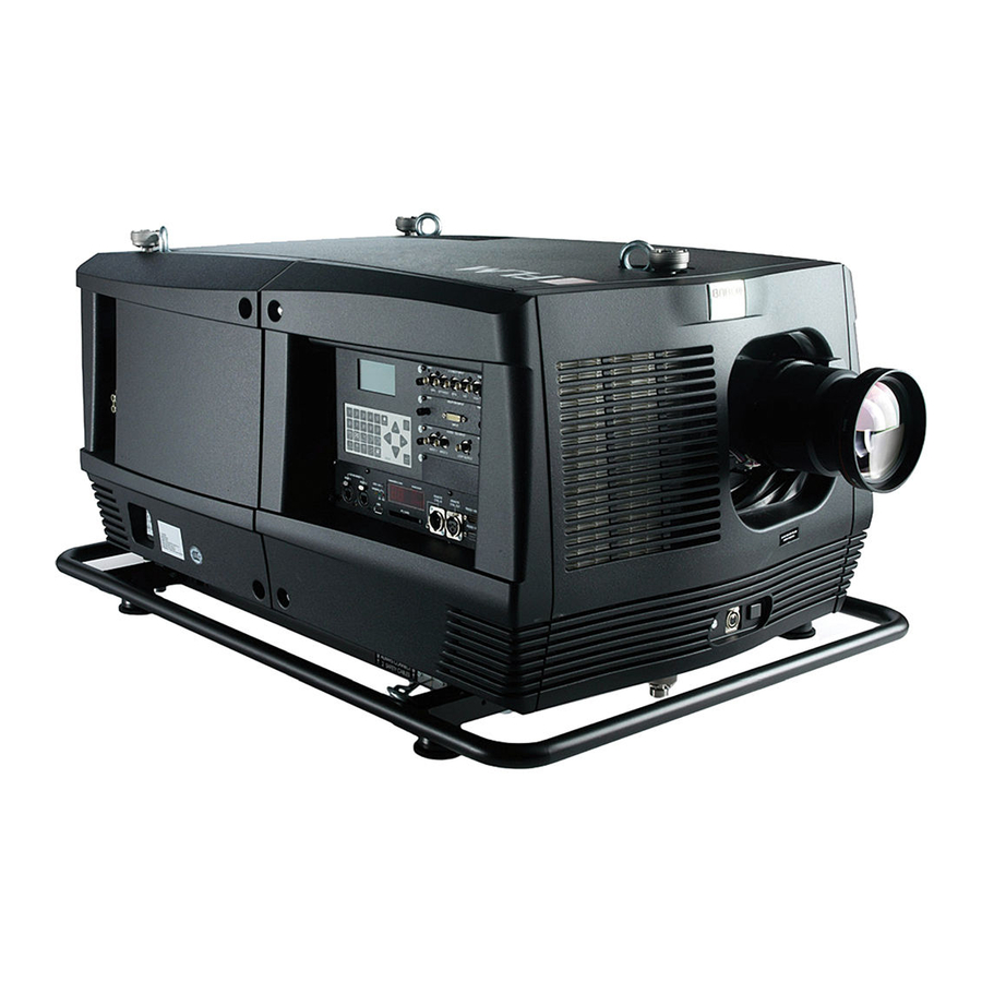
- Page 1 FLM HD20 User guide R59770180/00 11/07/2008...
- Page 2 Barco nv Media & Entertainment Division Noordlaan 5, B-8520 Kuurne Phone: +32 56.36.89.70 Fax: +32 56.36.883.86 E-mail: sales.events@barco.com Visit us at the web: www.barco.com Printed in Belgium...
- Page 3 Changes Barco provides this manual ’as is’ without warranty of any kind, either expressed or implied, including but not limited to the implied war- ranties or merchantability and fitness for a particular purpose. Barco may make improvements and/or changes to the product(s) and/or the program(s) described in this publication at any time without notice.
-
Page 5: Table Of Contents
Input configuration ......................60 R59770180 FLM HD20 11/07/2008... - Page 6 12.5.7 4 corner correction ......................123 R59770180 FLM HD20 11/07/2008...
- Page 7 16.5 Installation of the input & communication unit ..................175 R59770180 FLM HD20 11/07/2008...
- Page 8 Index........................213 R59770180 FLM HD20 11/07/2008...
-
Page 9: Safety
Restricted access location The FLM HD20 must be installed in a restricted access location, due to the temperature rise of parts of the equipment (air outlet). Restricted access location... -
Page 10: Important Safety Instructions
• The power cord of the FLM HD20 is equipped with a 3-wire grounding plug, a plug having a third (grounding) pin. This plug will only fit into a grounding-type IEC 60309 power outlet. This is a safety feature. Mains power cord with IEC 60309 plug: IEC60309 Warning: This apparatus must be grounded (earthed) via the supplied 3 conductor AC power cable. - Page 11 Caution: High pressure lamp may explode if improperly handled. Refer servicing to qualified service personnel. The customer should never attempt to disassemble the lamp casing or to dispose of the lamp casing other than by returning it to Barco. •...
- Page 12 To prevent device damage • The FLM HD20 has been designed for use with a specific lamp (house) type. See installation instructions for its correct type. • If the air filters are not regularly replaced, the air flow inside the projector could be disrupted, causing overheating. Overheating may lead to the projector shutting down during operation.
- Page 13 If the product exhibits a distinct change in performance, indicating a need for service. • Replacement parts: When replacement parts are required, be sure the service technician has used original Barco replace- ment parts. Unauthorized substitutions may result in degraded performance and reliability, fire, electric shock or other hazards.
- Page 14 1. Safety R59770180 FLM HD20 11/07/2008...
-
Page 15: General
Projector weight Do not underestimate the weight of one Barco FLM HD20, which is about ±100 kg (±225 lb.). Be sure that the table or truss instal- lation on which the projector(s) has to be installed is capable of handling five (5) times the complete load of the complete system. -
Page 16: Unpacking The Projector
Note: The two smaller carton boxes contain the manuals, the remote control unit (RCU), two standard batteries size AA and four rigging clamps for projector suspension. Image 2-2 R59770180 FLM HD20 11/07/2008... -
Page 17: Box Content
This check should confirm that there are no broken knobs or connectors, that the cabinet and panel surfaces are free of dents and scratches, and that the meter face and operating panel are not scratched of cracked. The Barco sales and service office should be notified as soon as possible. -
Page 18: Flm Flight Case
Introduction of the FLM flight case The FLM flight case is designed to transport the FLM HD20 in a safe and secure manner. The four caster wheels, provided with breaks, and the eight handles make the FLM flight case easy to handle. The floor of the flight case wagon is equipped with two small covered compartments to store the remote control and the rigging clamps. -
Page 19: Rear Projection
2. General AUDIENCE FLOOR Image 2-6 Rear projection The projector is installed, either in a table mount or ceiling mount configuration, at the other side of the screen opposite the audience. AUDIENCE BACKSTAGE FLOOR Image 2-7 R59770180 FLM HD20 11/07/2008... -
Page 20: Positioning The Projector
field of view (F) as illustrated below. Within these shift ranges the projector and lens perform excellently. Configuring the projector outside these shift ranges will result in a slight decline of image quality. R59770180 FLM HD20 11/07/2008... - Page 21 Always respect the allowed tilt range of the projector. Neglecting this will result in lamp flicker, which reduces the light output and the life span of the lamp substantially. Furthermore, in the long term, the possibility exist that the lamp explodes. R59770180 FLM HD20 11/07/2008...
-
Page 22: Projector Air Inlets And Outlets
Image 2-11 The FLM HD20 has 5 air inlet channels and one air outlet. The air outlet is located at the rear of the projector. The air inlets are located at the front, bottom, top and right side of the projector. -
Page 23: Physical Installation
The remote control unit (A) of the FLM projector is equipped with a rugged case (B) and an XLR adaptor (C). The remote control unit can be used wired via mini-jack or via rugged XLR. Note that the backlight, of the remote control unit, illuminate continuously when wire connected. Image 3-1 Remote control unit (RCU). Rugged case. XLR adaptor. R59770180 FLM HD20 11/07/2008... -
Page 24: Rcu Battery Installation
To prevent battery explosion • Danger of explosion if battery is incorrectly installed. • Replace only with the same or equivalent type recommended by the manufacturer. • Dispose of used batteries according to the manufacturer’s instruction. R59770180 FLM HD20 11/07/2008... -
Page 25: Rcu Rugged Case Installation
1. Connect a cable with XLR plug into the XLR adaptor. 2. Connect the other end of the cable with your FLM HD20. 3. Push the XLR adaptor completely against the rugged case of the remote control unit, as illustrated in the left image below, for wired communication. -
Page 26: Rcu Usage Possibilities
RCU with rugged case and XLR adaptor The RCU will send the commands via the cable connected with the XLR pushed in “WIRED” and wired adaptor to the projector. Backlight illuminates continuously when wire is connected. Infra red disabled. Image 3-8 R59770180 FLM HD20 11/07/2008... -
Page 27: Lenses
Lenses 3.2.1 Available lenses Available lenses for the FLM HD20 projector The TLD HB (High Brightness) lens series can be used on the FLM HD20 projector. Image 3-9 Image 3-10 Image 3-11 R9842040: TLD HB fixed lens (0.8 : 1) R9840770: TLD fixed lens (1.2 : 1) -
Page 28: Lens Formulas
2. Take the lens assembly out of its packing material and remove the lens caps on both sides. 3. Place the lens holder in the “unlocked” position by moving the lens lock handle (A) towards the lens power supply socket (B) as illustrated. R59770180 FLM HD20 11/07/2008... - Page 29 7. Secure the lens in the lens holder by sliding the lens lock handle into the “locked” position, which is away from the lens power supply socket. Ensure the lens touches the front plate of the lens holder. Image 3-19 8. Check if the lens is really secured by trying to pull the lens out of the lens holder. R59770180 FLM HD20 11/07/2008...
-
Page 30: Lens Removal
It’s recommended to place the foam rubber of the original projector packaging, back in the lens opening to prevent intrusion of dust. Note that this foam rubber is packed in a plastic bag to prevent that dust, emitted by the foam, enters the projector. R59770180 FLM HD20 11/07/2008... -
Page 31: Alignment Of A Table Mount Flm Projector
3. Release the lock nut (ref B image 3-24) of the rigging clamps. 4. Adjust the height of the rigging clamps with respect to the projector, until the projected hatch pattern is perfectly rectangle shaped and leveled. Image 3-24 R59770180 FLM HD20 11/07/2008... -
Page 32: Suspension Of The Flm Projector With Rigging Clamps
To release the nuts of the rigging points use a 24 mm open ended spanner. Ensure that the rigging points are symmetrically lined up, so that the projector will hang in balance. Warning: Be careful while working with heavy loads. Warning: Always secure the rigging points after adjustment. R59770180 FLM HD20 11/07/2008... - Page 33 4. Place all four rigging clamps in open position as illustrated. Image 3-30 5. Place the projector (upside down) under the truss installation and lower the truss until the support bars of the truss are nearby the rigging clamps mounted on the projector. R59770180 FLM HD20 11/07/2008...
- Page 34 8. Install a safety chain (S) around both sides of the carrying handle and around the truss. Image 3-32 9. Lift up the truss with attached projector to the desired height. Proceed with the alignment procedure, see "Alignment of a ceiling mount FLM projector", page 27. R59770180 FLM HD20 11/07/2008...
-
Page 35: Stacking Flm Projectors
In case of stacking projectors for a ceiling mount configuration, first turn the projectors upside down before placing the projectors on top of each other. Image 4-1 3. Attach the two projectors together by closing all three interlocking adapters as illustrated. Image 4-2 R59770180 FLM HD20 11/07/2008... - Page 36 ARNING Always use both safety cables of the lowest projector to secure a stacked projector in a ceiling mount configuration. How to open an interlocking adapter ? 1. Open an interlocking adaptor as illustrated. Image 4-5 R59770180 FLM HD20 11/07/2008...
-
Page 37: Aligning Stacked Flm Projectors
8 mm Allen key. The screw Q is located behind the cover of the lamp, just above the volt meter. Adjust until the outline of the hatch pattern is most symmetric with the reference hatch pattern. Note: See procedure "Removal of the lamp cover", page 181, to access the skew adjustment screw Q. R59770180 FLM HD20 11/07/2008... - Page 38 8. If necessary, repeat from step 2 until the hatch pattern of the stacked projector is perfectly aligned with the hatch pattern of the reference projector. In case of a triple stacked table mount projector configuration adjust and align first the bottommost projector (reference), than the projector in the middle and finally the uppermost projector. R59770180 FLM HD20 11/07/2008...
-
Page 39: Connections
5. Connections 5. CONNECTIONS About this chapter This chapter describes more in detail the power (P), the input source (S) and the communication (C) connections of the FLM HD20. Image 5-1 Overview • Power connection • Input source connections •... - Page 40 first to access this spare power plug, see "Removal of the lamp cover", page 181. Note that only qualified technical personnel may install a new power plug. HAN Q4/2 + Image 5-3 Pin configuration power plug HAN Q4/2 + PE. R59770180 FLM HD20 11/07/2008...
-
Page 41: Input Source Connections
Image 5-5 Image 5-6 Image 5-7 5 Cable input (Multi purpose) (R9854430). HDSDI - SDI input (R9854450). DVI input (R9854460). Image 5-8 Cover plate for unused input slot (R848607). HDCP DVI input (R9854465) (Image not available) R59770180 FLM HD20 11/07/2008... -
Page 42: Communication Connections
5. Connections The FLM HD20 is standard equipped with one 5 cable input module, one HDSDI - SDI input module and one DVI input module. Input slot number 4 (lowermost) is covered with a input cover plate. For more information about the FLM input modules see chapter “Specifications”. -
Page 43: Wired Remote Control
RS232/422 serial communication The communication interface of the FLM HD20 supports RS232 and RS422 serial communication. You can use the RS232/RS422 input port (O) to connect a local PC to your FLM projector. This way you can configure and control your FLM projector from your local PC. - Page 44 RJ45 cable connector. Straight (most common) as well as cross linked network cables can be used. The 2 ports are functionally identical. Both ports are connected via the projector hub (Auto sensing enabled). 10/100 Base-T — RJ45 port Pin Description TXD+ TXD- R59770180 FLM HD20 11/07/2008...
-
Page 45: Usb Port
USB port and files can be transferred from or to the projector using the local or remote control unit. Note that the USB-stick has to be FAT16 compatible. Card bus connector (PCMCIA) No cards supported yet. R59770180 FLM HD20 11/07/2008... - Page 46 5. Connections R59770180 FLM HD20 11/07/2008...
-
Page 47: Getting Started
• switching to "pause" (blanked picture, full power for immediate restarting) • direct access to all connected sources. Terminology overview Overview The following table gives an overview of the different functionality of the keys. R59770180 FLM HD20 11/07/2008... - Page 48 Use these buttons to obtain the desired picture level. PHASE Used to remove the horizontal instability of the image (usually for RGB source). It adjusts the phase of the pixel sampling clock relative to the incoming signal. R59770180 FLM HD20 11/07/2008...
-
Page 49: Operating The Projector
The actual input voltage is indicated on the voltmeter just above the power switch. Starting image projection via the standby key. 1. Press Stand by key once on the local keypad or on the remote control. R59770180 FLM HD20 11/07/2008... -
Page 50: Errors, Warnings And Messages During Start Up
All custom settings are written to the internal backup device. A message ’Save data ...’ indicates this process. Never switch off the projector while this message is displayed. 6.3.4 Switching off How to switch off the projector? 1. Press first Standby. R59770180 FLM HD20 11/07/2008... -
Page 51: Using The Rcu
2. Plug the other end in the small connector in the input panel of the projector labeled Remote CTRL in. The Remote connection uses a standard two wire cable terminated on each end with a 3.5 mm male (mono/stereo) phone jack. This cable is not delivered but is available in most electronic or audio shops. R59770180 FLM HD20 11/07/2008... -
Page 52: Quick Setup Adjustments
To toggle Text ON or OFF, press the TEXT key on the remote control or local keypad. 6.5.2 Quick Lens Adjustment 6.5.2.1 Quick Lens Adjustment via LENS key Quick zoom/focus adjustment 1. Press the LENS key on the remote control or local keypad. R59770180 FLM HD20 11/07/2008... -
Page 53: Direct Lens Adjustment (Rcu)
On the Remote Control four buttons with double action are provided, allowing direct alignment for lens ZOOM, FOCUS, HORIZON- TAL SHIFT and VERTICAL SHIFT. 1. Press LENS ZOOM button [-] or [+] (A) for correct image size on the screen. R59770180 FLM HD20 11/07/2008... -
Page 54: Quick Picture In Picture
1. Press Menu to activate the menus and select with the ▲ or ▼ key Projector Control and press ENTER. 2. Select with the ▲ or ▼ key Language and press ENTER. The language menu opens. 3. Select with the ▲ or ▼ key the desired language and press ENTER to activate. R59770180 FLM HD20 11/07/2008... -
Page 55: Projector Address
2. Enter the address with the digit buttons within 5 seconds after pushing the address key. Note: That address can be any digit between 0 and 9. The LED on the remote control must lit up while pressing a digit key. Otherwise the address is not entered in the remote control. R59770180 FLM HD20 11/07/2008... -
Page 56: Controlling The Projector
To select the source for the picture in picture window, press Window button until PiP window is activated and then select the desired source with the digit keys. To select the source for the main window, press Window button until the main window is activated and then select the desired source with the digit keys. R59770180 FLM HD20 11/07/2008... -
Page 57: Controlling The Projector
When the Stand-by key is pressed, the image projection is stopped and the projector goes to stand-by. This situation is used when a projection stop is planned for a longer period. All custom settings are saved to an internal backup device. A message ’Save data ...’ is displayed during this backup operation. R59770180 FLM HD20 11/07/2008... - Page 58 6. Getting started R59770180 FLM HD20 11/07/2008...
-
Page 59: Start Up Of The Adjustment Mode
To start up the adjustment mode, use the remote control or the local keypad. How to start up? 1. Press Menu on the remote control (RCU) or on the local keypad to start up the Adjustment mode. R59770180 FLM HD20 11/07/2008... -
Page 60: Navigation And Adjustments
These menus can be used in the same way as the on-screen menus. The menus on the LCD panel are still reachable even when the projector lamp is not activated and when Text is in the off mode. R59770180 FLM HD20 11/07/2008... - Page 61 7. Start up of the Adjustment Mode When quitting the menu structure, the backlighting of the LCD panel is switched off after a few seconds. R59770180 FLM HD20 11/07/2008...
- Page 62 7. Start up of the Adjustment Mode R59770180 FLM HD20 11/07/2008...
-
Page 63: Input Menu
For more information about the available input modules and how to install, see "Input source connections", page 37. AUTION Always install a cover plate on an unused input slot. This to prevent dust intrusion into the pro- jector. R59770180 FLM HD20 11/07/2008... -
Page 64: Input Configuration
For RGB selections, advanced settings are possible. To adjust these advanced settings, use the ▲ or ▼ key to select Advanced settings and press ENTER. The advanced settings menu opens: Image 8-5 Press ENTER to toggle between [Analog] and [TTL]. R59770180 FLM HD20 11/07/2008... -
Page 65: Input Locking
The input locking window is displayed. The actual selected locking method is indicated by an arrow. 4. Use the ▲ or ▼ key to select the desired locking and press ENTER. Image 8-8 Image 8-9 Image 8-7 R59770180 FLM HD20 11/07/2008... - Page 66 The next digit in the value will be automatically selected. to change the clock frequency, use the ▲ or ▼ key to select Clock freq and press ENTER to activate. The first digit is selected. R59770180 FLM HD20 11/07/2008...
-
Page 67: Minimum Delay
3. Use the ▲ or ▼ key to select Minimum delay and press ENTER to toggle between [On] and [Off]. Image 8-13 Image 8-12 Native resolution What can be done The aim here is to always show the resolution of the source independently of the resolution of the DMD panels. R59770180 FLM HD20 11/07/2008... - Page 68 3. Use the ▲ or ▼ key to select Native resolution and press ENTER to toggle between [On] and [Off]. [On] : images displayed in native resolution [Off] : images scaled to fill the complete screen Image 8-16 Image 8-15 R59770180 FLM HD20 11/07/2008...
-
Page 69: Source Switching
▲ or ▼ key to scroll until the desired time is reached. Press ENTER to activate. Image 8-20 Image 8-19 Image 8-18 No signal Overview • Background color • Shutdown setting • Shutdown retarding time R59770180 FLM HD20 11/07/2008... -
Page 70: Background Color
Shutdown retarding time Only accessible when Shutdown is set to [On]. How to set the retarding time? 1. Press MENU to activate the menus. 2. Use the ▲ or ▼ key to select Input and press ENTER. R59770180 FLM HD20 11/07/2008... - Page 71 4. Use the ▲ or ▼ key to change the value. enter the desired value with the keyboard. When trying to exceed the maximum allowed value, the system will set it back to the maximum value. Image 8-29 Image 8-28 Image 8-27 R59770180 FLM HD20 11/07/2008...
- Page 72 8. Input menu R59770180 FLM HD20 11/07/2008...
-
Page 73: Image Menu
Noise reduction Color temperature Projector white Computer 9300K Video 6500K Film 5400K Broadcast 3200K Custom balance Input balance Aspect ratio 16/9 2.35 1.88 1.78 Custom Timings Total pixels Active pixels Horizontal start Period Total lines Active lines R59770180 FLM HD20 11/07/2008... -
Page 74: How To Select The Image Adjustments
2. Press ENTER to select. The Image menu opens. Image 9-2 Image 9-1 Image Settings Overview • Contrast • Brightness • Saturation • Tint (hue) • Phase • Sharpness • Noise reduction • Color temperature • Input balance R59770180 FLM HD20 11/07/2008... -
Page 75: Contrast
3. Use the ▲ or ▼ key to select Image settings and press ENTER. 4. Use the ▲ or ▼ key to select Brightness and press ENTER. The Brightness progress bar appears. 5. Use ◄ or ► to change the brightness. R59770180 FLM HD20 11/07/2008... -
Page 76: Saturation
4. Use the ▲ or ▼ key to select Saturation and press ENTER. The Saturation progress bar appears. 5. Use ◄ or ► to change the color saturation. The higher the value, the higher the color saturation. Image 9-12 Image 9-11 Image 9-13 Image 9-14 R59770180 FLM HD20 11/07/2008... -
Page 77: Tint (Hue)
When displaying computer patterns or graphics (RGB or YUV signals) which are very detailed (tilting, vertical stripes, etc. ), jitter in picture (mis-sampling) may occur, causing horizontal stripes in portions of the screen. When this jitter occurs, adjust ’Phase’ for optimum image. Image 9-19 Jittering on image R59770180 FLM HD20 11/07/2008... -
Page 78: Sharpness
3. Use the ▲ or ▼ key to select Image settings and press ENTER. 4. Use the ▲ or ▼ key to select Sharpness and press ENTER. The Sharpness progress bar appears. 5. Use ◄ or ► to change the sharpness. The higher the value, the higher the sharpness. R59770180 FLM HD20 11/07/2008... -
Page 79: Noise Reduction
4. Use the ▲ or ▼ key to select Noise reduction and press ENTER. The Noise reduction progress bar appears. 5. Use ◄ or ► to change the noise reduction. The higher the value, the higher the noise reduction. Image 9-29 Image 9-28 Image 9-30 Image 9-31 R59770180 FLM HD20 11/07/2008... -
Page 80: Color Temperature
5. Use the ▲ or ▼ key to select a predefined color temperature value, e.g. Video, and press ENTER. The colors of the image is switched to the selected value. Image 9-33 Image 9-32 Image 9-34 R59770180 FLM HD20 11/07/2008... -
Page 81: Set A Custom Color Temperature
6. Adjust gain red with ◄ or ► key. Use the ▲ or ▼ key to toggle to gain blue and back again. Adjust gain blue in the same way as gain red. 7. When gain adjustment is finished press ENTER. Image 9-37 Image 9-36 Image 9-38 Image 9-40 Image 9-39 R59770180 FLM HD20 11/07/2008... -
Page 82: Input Balance
A typical ADC transforms the analog value into an 8 bit coded digital signal. The graphic shows that when converting a signal containing a DC offset component the range of the converter is not optimally used. i2 : video information i1 : superfluous information Δ Black level Image 9-43 R59770180 FLM HD20 11/07/2008... -
Page 83: Adjusting The Input Balance
Black balance : In the projector, we will set the brightness for each color until we get a 0% light output picture when projecting a 100% black image (image B). The changeover from min to max is indicated by the apparition of bright spots also called “digital noise” R59770180 FLM HD20 11/07/2008... -
Page 84: Black Balance
10.Toggle with ▲ or ▼ key to Black balance blue adjust the Blue black level until bright spots appear on the screen. 11. Toggle with ▲ or ▼ key to Black balance red adjust the Red black level until bright spots appear on the screen. The projected image should now be noisy full black R59770180 FLM HD20 11/07/2008... -
Page 85: Aspect Ratio
Relation between the horizontal & vertical dimension in which the window will be displayed, e.g. 4 by 3 or 16 by 9. Can also be expressed as a decimal number, such as 1.77. The larger the ratio or decimal, the wider are less square the image. R59770180 FLM HD20 11/07/2008... -
Page 86: How To Select An Aspect Ratio
The Custom aspect ratio dialog box opens. 2. Use the ▲ or ▼ key to adjust the vertical size of the image. Use the key to adjust the horizontal size of the image. When the desired aspect ratio is obtained, press EXIT. R59770180 FLM HD20 11/07/2008... -
Page 87: Timings
3. Use the ▲ or ▼ key to select Timings and press ENTER. The timings menu will be displayed. Image 9-63 Image 9-62 Image 9-64 4. To change a setting, use the ▲ or ▼ key to select and press ENTER. R59770180 FLM HD20 11/07/2008... -
Page 88: Advanced Settings
The Advanced settings menu is displayed. 5. Use the ▲ or ▼ key to select Clamp delay or Clamp width and press ENTER. A progress bar appears. 6. Use the ▲ or ▼ key to change the setting. R59770180 FLM HD20 11/07/2008... - Page 89 3. Use the ▲ or ▼ key to select Advanced settings and press ENTER. The Advanced settings menu is displayed. 4. Use the ▲ or ▼ key to select Field polarity and press ENTER to toggle between [neg] or [pos]. Image 9-72 Image 9-71 Image 9-73 R59770180 FLM HD20 11/07/2008...
-
Page 90: Advanced Settings, Film Mode Detection
3. Use the ▲ or ▼ key to select Advanced settings and press ENTER. The Advanced settings menu is displayed. 4. Use the ▲ or ▼ key to select Film mode and press ENTER to toggle between [auto] or [off]. R59770180 FLM HD20 11/07/2008... -
Page 91: Image Files Services
When the new source corresponds with one of these files, the file can be loaded and saved for future use. When there is a little difference, the file can also be loaded and then edited until the source specs are reached. VESA standards and video standards are pre-programmed. R59770180 FLM HD20 11/07/2008... -
Page 92: Manual Load File
7. Press ENTER to select. The selected file is loaded. The image is not perfect? If the displayed image is not correct after selecting the best fitting file, go to the Timings menu and change the file settings. R59770180 FLM HD20 11/07/2008... -
Page 93: Delete File
4. Use the ▲ or ▼ key to select Delete all and press ENTER. A delete all confirmation window opens. 5. Use the ▲ or ▼ key to select Yes if you are sure to delete all custom files and press ENTER to activate the selection. R59770180 FLM HD20 11/07/2008... -
Page 94: Rename A File
Note: Digits can be entered with the digit keys on the remote control or on the local keypad. When a digit is entered in that way, the next character will be selected automatically. 8. Press ENTER to finalize the rename action. Image 9-92 Image 9-93 Image 9-91 R59770180 FLM HD20 11/07/2008... -
Page 95: Copy A File
8. Press ENTER to finalize the copy action. Image 9-97 Image 9-98 Image 9-96 Image 9-100 Image 9-99 9.6.7 File options How to set the options? 1. Press MENU to activate the menus. R59770180 FLM HD20 11/07/2008... -
Page 96: Save Custom Settings
3. Use the ▲ or ▼ key to select Save custom settings and press ENTER. The custom settings are written to the internal backup device. A message menu “Save data ...” is displayed during the save operation. R59770180 FLM HD20 11/07/2008... - Page 97 9. Image menu Image 9-107 Image 9-105 Image 9-106 R59770180 FLM HD20 11/07/2008...
- Page 98 9. Image menu R59770180 FLM HD20 11/07/2008...
-
Page 99: Layout Menu
When the active layout is a read only layout, the projector will ask to create a new layout. Use the ▲ or ▼ key to select Yes or No and press ENTER. If Yes is selected an Enter layout name window opens. Image 10-2 Image 10-1 R59770180 FLM HD20 11/07/2008... -
Page 100: Size Adjustment
3. Use the ▲ or ▼ key to select Main Window and press ENTER. The main window opens. 4. Use the ▲ or ▼ key to select Size and press ENTER. The size adjustment window opens. Image 10-6 Image 10-5 Image 10-4 R59770180 FLM HD20 11/07/2008... -
Page 101: How To Adjust Height And Width Separately
The main window opens. 4. Use the ▲ or ▼ key to select Size and press ENTER. The size adjustment window opens. Image 10-11 Image 10-10 Image 10-9 5. Toggle with ENTER till Lock is set to [ ]. R59770180 FLM HD20 11/07/2008... -
Page 102: Position Adjustment
3. Use the ▲ or ▼ key to select Main Window and press ENTER. The main window opens. 4. Use the ▲ or ▼ key to select Position and press ENTER. The position adjustment window opens. 5. Use the ▲ or ▼ key to adjust top start point. R59770180 FLM HD20 11/07/2008... -
Page 103: Pip Window
The input section of the projector allows a combinations of different input signals which may be projected in the 2 windows of the PiP screen. The PiP window can be placed anywhere, with any dimensions, on the screen by changing its position and its size. R59770180 FLM HD20 11/07/2008... -
Page 104: Picture In Picture Activation
RCU. 10.3.3 Picture in Picture size of the window What can be done? The width and height of the picture in picture window can be changed till the desired dimensions are obtained. R59770180 FLM HD20 11/07/2008... - Page 105 The main window opens. 4. Use the ▲ or ▼ key to select Size and press ENTER. The size adjustment window opens. Image 10-28 Image 10-27 Image 10-26 5. Toggle with ENTER till Lock is set to [x]]. R59770180 FLM HD20 11/07/2008...
-
Page 106: How To Change The Height And Width Separately
The main window opens. Image 10-33 Image 10-32 Image 10-31 4. Use the ▲ or ▼ key to select Size and press ENTER. The size adjustment window opens. 5. Toggle with ENTER till Lock is set to [ ]. R59770180 FLM HD20 11/07/2008... -
Page 107: Picture In Picture, Position Window
The size adjustment window opens. 5. Use the ▲ or ▼ key to adjust Top Use the ◄ or ► key to adjust Left When the desired position is reached, press EXIT. A Save window opens. R59770180 FLM HD20 11/07/2008... -
Page 108: Layout File Services
2. Use the ▲ or ▼ key to select Window and press ENTER. 3. Use the ▲ or ▼ key to select Layout and press ENTER. The layout services window opens. 4. Use the ▲ or ▼ key to select Load and press ENTER. R59770180 FLM HD20 11/07/2008... -
Page 109: Rename A Layout
Note: Digits can be entered with the digit keys on the remote control or on the local keypad. When a digit is entered in that way, the next character is selected automatically. 7. Press ENTER to save the new name. R59770180 FLM HD20 11/07/2008... -
Page 110: Delete A Layout
3. Use the ▲ or ▼ key to select Layout services and press ENTER. The layout services window opens. 4. Use the ▲ or ▼ key to select Delete and press ENTER. The Delete window opens. Image 10-51 Image 10-50 Image 10-49 R59770180 FLM HD20 11/07/2008... -
Page 111: Copy / Save As A Layout
Note: Digits can be entered with the digit keys on the remote control or on the local keypad. When a digit is entered in that way, the next character is selected automatically. 7. Press ENTER to copy to the new name. The new layout will be added to the list of layouts. Image 10-55 Image 10-54 Image 10-53 R59770180 FLM HD20 11/07/2008... - Page 112 10. Layout menu Image 10-56 R59770180 FLM HD20 11/07/2008...
-
Page 113: Lamp Menu
2. Use the ▲ or ▼ key to select Lamp and press ENTER. 3. Use the ▲ or ▼ key to select Power and press ENTER. 4. Use the ▲ or ▼ key to select Mode. 5. Press ENTER to toggle between [Normal] and [Economic]. R59770180 FLM HD20 11/07/2008... -
Page 114: Lamp Power
5. Use the ▲ or ▼ key to change the lamp power. Image 11-6 Image 11-5 Image 11-4 Image 11-7 11.4 Lamp Identification About The lamp identification menu gives an overview of the most important parameters of the used lamp. R59770180 FLM HD20 11/07/2008... -
Page 115: Z-Axis Adjustment
2. Use the ▲ or ▼ key to select Lamp and press ENTER. 3. Use the ▲ or ▼ key to select Z-axis and press ENTER. The Z-axis dialog box is display and indicates the current light output.. R59770180 FLM HD20 11/07/2008... - Page 116 11. Lamp menu Image 11-13 Image 11-12 Image 11-11 R59770180 FLM HD20 11/07/2008...
-
Page 117: Alignment Menu
Orientation Front Table Front Ceiling Rear Table Rear Ceiling Lens Zoom/Focus Shift Mid position Side keystone Warp Horizontal keystone Vertical keystone Rotation Pincushion / Barrel 4 corners Load file Blanking Bottom Left Right Reset Contrast enhancement R59770180 FLM HD20 11/07/2008... -
Page 118: Orientation
2. Use the ▲ or ▼ key to select Alignment and press ENTER. 3. Use the ▲ or ▼ key to select Orientation and press ENTER. 4. Use the ▲ or ▼ key to select the correct orientation and press ENTER. R59770180 FLM HD20 11/07/2008... -
Page 119: Lens Adjustment
3. Use the ▲ or ▼ key to select Lens and press ENTER. The lens adjustment menu is displayed. Image 12-6 Image 12-4 Image 12-5 Zoom/focus the lens 1. Use the ▲ or ▼ key to select Zoom/Focus and press ENTER. Image 12-8 Image 12-7 R59770180 FLM HD20 11/07/2008... -
Page 120: Side Keystone
The side keystone adjustment is used to align the image if the projector is mounted at a non standard projection angle. Image 12-12 Side keystone Keystone adjustment with positive values Keystone adjustment with negative values Side keystone adjustment 1. Press MENU to activate the menus. R59770180 FLM HD20 11/07/2008... -
Page 121: Warp Geometry Settings
While an image can be transformed in various ways, pure warping means that points are mapped to points without changing the colors. Some examples of projected images which need to be corrected with the warp geometry settings: R59770180 FLM HD20 11/07/2008... -
Page 122: Warp Status
[Manual] : projector functions for warp are available. [File] : Sophisticated warp adjustments can be loaded via a file. The projector warp functions are not available. [Off] : No warp adjustments used in the projected image. Image 12-18 Image 12-19 Image 12-20 R59770180 FLM HD20 11/07/2008... -
Page 123: Horizontal Keystone Correction
3. Use the ▲ or ▼ key to select Warp and press ENTER. The warp dialog box appears. 4. Use the ▲ or ▼ key to select Horizontal keystone and press ENTER. 5. Use ◄ or ► to change the horizontal keystone. Image 12-22 Image 12-23 Image 12-24 R59770180 FLM HD20 11/07/2008... -
Page 124: Vertical Keystone Correction
3. Use the ▲ or ▼ key to select Warp and press ENTER. The warp dialog box appears. 4. Use the ▲ or ▼ key to select Vertical keystone and press ENTER. 5. Use ◄ or ► to change the vertical keystone. R59770180 FLM HD20 11/07/2008... -
Page 125: Rotation
3. Use the ▲ or ▼ key to select Warp and press ENTER. The warp dialog box appears. 4. Use the ▲ or ▼ key to select Rotation and press ENTER. 5. Use ◄ or ► to change the rotation angle. R59770180 FLM HD20 11/07/2008... -
Page 126: Pincushion - Barrel Correction
3. Use the ▲ or ▼ key to select Warp and press ENTER. The warp dialog box appears. 4. Use the ▲ or ▼ key to select Pincushion/Barrel and press ENTER. 5. Use ◄ or ► to adjust the pincushion or the barrel distortion. R59770180 FLM HD20 11/07/2008... -
Page 127: Corner Correction
2. Use the ▲ or ▼ key to select Alignment and press ENTER. 3. Use the ▲ or ▼ key to select Warp and press ENTER. The warp dialog box appears. 4. Use the ▲ or ▼ key to select 4 corners and press ENTER. R59770180 FLM HD20 11/07/2008... -
Page 128: Reset Warp Settings
3. Use the ▲ or ▼ key to select Warp and press ENTER. The warp dialog box appears. 4. Use the ▲ or ▼ key to select Reset and press ENTER. All warp settings are reset. The Status is set to [Off]. Image 12-47 Image 12-48 Image 12-49 R59770180 FLM HD20 11/07/2008... -
Page 129: Load Warp File
5. Use the ▲ or ▼ key to select the desired file out of the list and press ENTER. The file is loaded and the corrections are applied. Image 12-51 Image 12-52 Image 12-53 Image 12-54 12.6 Contrast enhancement Purpose Increase the contrast for all video and data sources. R59770180 FLM HD20 11/07/2008... -
Page 130: Blanking
(or noise). A ’0’ on the bar scale indicates no blanking. Which blanking adjustments are available ? • top blanking • bottom blanking • left blanking • right blanking R59770180 FLM HD20 11/07/2008... -
Page 131: Gamma
12.8 Gamma About Gamma Gamma is an image quality enhancement function that offers a richer image by brightening the already darker portions of the image without altering the brightness of the brighter portions (contrast feeling enhanced). R59770180 FLM HD20 11/07/2008... -
Page 132: Internal Pattern
4. Use the ▲ or ▼ key to scroll through the possible selection and press ENTER to activate the selected pattern. Select ▲ or ▼ in the menu to display the previous or next page with possible internal patterns. Image 12-68 Image 12-66 Image 12-67 R59770180 FLM HD20 11/07/2008... -
Page 133: Color Space
The user can define the x and y coordinates for red, green and blue which forms the corners of the color space. By changing the coordinates, the color reproduction can be changed. Image 12-71 Image 12-69 Image 12-70 R59770180 FLM HD20 11/07/2008... -
Page 134: Scenergix
Why ScenergiX ? When working in a multichannel setup the FLM HD20 and its Soft Edge possibilities enable an image blending that gives the ap- pearance of a single view, thus achieving realistic immersion for the majority of wide screen applications. -
Page 135: Preparations
3. Use the ▲ or ▼ key to select ScenergiX and press ENTER. 4. Use the ▲ or ▼ key to select Status and press ENTER to toggle between [On] and [Off]. ScenergiX is active ScenergiX is not active Image 12-77 Image 12-75 Image 12-76 R59770180 FLM HD20 11/07/2008... -
Page 136: Scenergix Overlap Zone (Horizontal Scenergix)
1. Go to Layout → Main window → Size 2. Enter the value for the Width as follow: Total horizontal screen resolution / 2 - 0.5 x overlap zone. 3. Position remains the same. Image 12-81 Image 12-80 Image 12-79 Image 12-82 R59770180 FLM HD20 11/07/2008... -
Page 137: Scenergix Overlap Zone (Vertical Scenergix)
Overlap : number of pixels that overlap Vertical resolution of 1 projector Total vertical screen resolution : [(Vertical resolution of 1 projector) x 2] minus (overlap) Vertical Resolution source : number of active lines of the source R59770180 FLM HD20 11/07/2008... - Page 138 2. Enter the value for the Width as follow: Total Vertical screen resolution / 2 - 0.5 x overlap zone. 3. Position = original start + Vertical height projector 1 - overlap zone Image 12-95 Image 12-94 Image 12-93 R59770180 FLM HD20 11/07/2008...
-
Page 139: Scenergix Size Adjustment
3. Use the ▲ or ▼ key to select ScenergiX and press ENTER. 4. Use the ▲ or ▼ key to select one of the four size adjustments and press ENTER. Image 12-100 Image 12-98 Image 12-99 A pattern with the different areas is displayed. R59770180 FLM HD20 11/07/2008... - Page 140 5. Use the cursor keys to move the border of the overlap area to the desired position (value between 0 and 255). Set first the width for the first projector and repeat for the second one. Image 12-102 Width set up for projector 1 R59770180 FLM HD20 11/07/2008...
-
Page 141: Adjusting The Black Level Of The Images
4. Use the ▲ or ▼ key to select Black level and press ENTER. Image 12-106 Image 12-104 Image 12-105 5. Adjust the black level of area A until the black level of area A, B and C are equal. R59770180 FLM HD20 11/07/2008... - Page 142 12. Alignment menu Image 2 Image 1 Image 12-107 Black level adjustment Use the Reset function to bring all ScenergiX settings back to zero. R59770180 FLM HD20 11/07/2008...
-
Page 143: Projector Control
RS422 termination [Off/On] Network DHCP [ON/OFF] IP-address Subnet mask Default gateway IR control IR Front [On/Off] IR Back [On/Off] IR Side [On/Off] Buttons Standby Shortcut keys Menu position Menu Bar scale Local LCD contrast Language English R59770180 FLM HD20 11/07/2008... -
Page 144: Projector Address
6. Use the ◄ or ► key to select the next digit and repeat step 5. 7. When the desired address is entered, press ENTER to store that address. Image 13-3 Image 13-2 Image 13-1 Image 13-4 R59770180 FLM HD20 11/07/2008... -
Page 145: Common Address
1. Press MENU to activate the menus. 2. Use the ▲ or ▼ key to select Projector control and press ENTER. 3. Use the ▲ or ▼ key to select Serial communication and press ENTER. The serial communication menu opens. R59770180 FLM HD20 11/07/2008... -
Page 146: Interface Standard
When the interface standard is set to RS422, the last projector in a line should be RS422 terminated (ON position). All others in the line should be in the OFF position. How to set 1. Press MENU to activate the menus. 2. Use the ▲ or ▼ key to select Projector control and press ENTER. R59770180 FLM HD20 11/07/2008... -
Page 147: Network
(WAN) or to the Internet. MAC address Media Access Control address. Unique hardware number, used in combination with the IP-address to connect to the network (LAN or WAN). R59770180 FLM HD20 11/07/2008... -
Page 148: Dhcp Setup
5. Use the ▲ or ▼ key to select the desired digit and press ◄ or ► key to select the next digit in the address. enter the value with the digit keys on the remote control or local keypad. The next digit in the address will be selected automati- cally. 6. Press EXIT to return. R59770180 FLM HD20 11/07/2008... -
Page 149: Subnet-Mask Set Up
The next digit in the address will be selected automati- cally. 6. Press EXIT to return. Image 13-27 Image 13-26 Image 13-25 Image 13-28 R59770180 FLM HD20 11/07/2008... -
Page 150: Default Gateway Set Up
3. Use the ▲ or ▼ key to select IR Control and press ENTER. 4. Use the ▲ or ▼ key to select the desired IR receiver and press ENTER to toggle this receiver [on] or [off]. R59770180 FLM HD20 11/07/2008... -
Page 151: Buttons
4. Use the ▲ or ▼ key to select Standby and press ENTER to toggle between [Lamp on/off] and [Power up/down]. Image 13-38 Image 13-37 Image 13-36 13.6.2 APA (auto) button What can be done? The function of the APA (auto) button can be configured according the wishes of the user. R59770180 FLM HD20 11/07/2008... -
Page 152: Shortcut Keys
5. Use the ▲ or ▼ key to select a shortcut with allocation and press ENTER to remove the allocation. The indication becomes No allocation and the key is free again for a new shortcut association. Image 13-44 Image 13-43 Image 13-42 R59770180 FLM HD20 11/07/2008... -
Page 153: Menu Position
3. Use the ▲ or ▼ key to select Menu position and press ENTER. 4. Use the ▲ or ▼ key to select Menu and press ENTER to toggle between [Center], [Top] and [Bottom]. Image 13-49 Image 13-48 Image 13-47 R59770180 FLM HD20 11/07/2008... -
Page 154: Bar Scale
2. Use the ▲ or ▼ key to select Projector control and press ENTER. 3. Use the ▲ or ▼ key to select Local LCD contrast and press ENTER. 4. Use the ▲ or ▼ key to adjust the local contrast. R59770180 FLM HD20 11/07/2008... -
Page 155: Language Selection
3. Use the ▲ or ▼ key to select Language and press ENTER. 4. Use the ▲ or ▼ key to select the desired language. The change will take effect immediately. Image 13-59 Image 13-58 Image 13-57 R59770180 FLM HD20 11/07/2008... - Page 156 13. Projector control R59770180 FLM HD20 11/07/2008...
-
Page 157: Service Menu
14. Service menu 14. SERVICE MENU About this chapter This chapter refers to the Service menu in which the customer can find valuable information when calling the Barco help desk. 14.1 Overview flow Overview Level 1 Level 2 Level 3 Service Identification... - Page 158 Use the ◄ or ► key to selected another character. Note: Digits can be entered with the digit keys on the remote control or on the local keypad. When a digit is entered in that way, the next character will be selected automatically. R59770180 FLM HD20 11/07/2008...
-
Page 159: Diagnosis
3. Use the ▲ or ▼ key to select Diagnosis and press ENTER. The diagnosis screen is displayed. 4. Use the ▲ or ▼ key to select Versions and press ENTER. The Versions overview is displayed. Image 14-10 Image 14-8 Image 14-9 R59770180 FLM HD20 11/07/2008... -
Page 160: Voltages
3. Use the ▲ or ▼ key to select Diagnosis and press ENTER. The diagnosis screen will be displayed. 4. Use the ▲ or ▼ key to select Voltages and press ENTER. The Voltage overview menu will be displayed. Image 14-14 Image 14-12 Image 14-13 Image 14-15 R59770180 FLM HD20 11/07/2008... -
Page 161: I²C Diagnosis
The service window opens. 3. Use the ▲ or ▼ key to select Diagnosis and press ENTER. The diagnosis screen will be displayed. 4. Use the ▲ or ▼ key to select Temperatures and press ENTER. R59770180 FLM HD20 11/07/2008... -
Page 162: Fan Speeds Overview
3. Use the ▲ or ▼ key to select Diagnosis and press ENTER. The diagnosis screen will be displayed. 4. Use the ▲ or ▼ key to select Fan speeds and press ENTER. The Fan speeds overview menu will be displayed. R59770180 FLM HD20 11/07/2008... -
Page 163: Spi
3. Use the ▲ or ▼ key to select Diagnosis and press ENTER. The diagnosis screen will be displayed. 4. Use the ▲ or ▼ key to select SPI and press ENTER. The SPI overview menu will be displayed. Image 14-30 Image 14-28 Image 14-29 R59770180 FLM HD20 11/07/2008... -
Page 164: Error Logging Overview
1. Press MENU to activate the menus. 2. Use the ▲ or ▼ key to select Service and press ENTER. The service window opens. 3. Use the ▲ or ▼ key to select Convergence and press ENTER. R59770180 FLM HD20 11/07/2008... -
Page 165: Internal Service Patterns
1. Press MENU to activate the menus. 2. Use the ▲ or ▼ key to select Service and press ENTER. The service window opens. 3. Use the ▲ or ▼ key to select Restore factory defaults and press ENTER. R59770180 FLM HD20 11/07/2008... -
Page 166: Reset Formatter
The current custom settings can be saved to the internal backup device in the same way as it would be done when the projector was switched to standby. How to save 1. Press MENU to activate the menus. R59770180 FLM HD20 11/07/2008... -
Page 167: Refill Mode
4. Use the ▲ or ▼ key to select Yes or No and press ENTER. Yes will switch the projector in refill mode. When No is selected, the projector stays in normal mode. Image 14-50 Image 14-48 Image 14-49 R59770180 FLM HD20 11/07/2008... -
Page 168: Broadcast Mode
An USB device, FAT 16 formatted can be used, to save custom settings from the projector or to load custom settings to the projector. This function is very handy to clone projectors. The following settings can be transported via an USB device: R59770180 FLM HD20 11/07/2008... - Page 169 1. Connect a FAT 16 formatted USB device to the USB port. 2. Press MENU to activate the menus. 3. Use the ▲ or ▼ key to select Service and press ENTER. The service window opens. R59770180 FLM HD20 11/07/2008...
- Page 170 6. Use the ▲ or ▼ key to select the serial number to start from to load the settings. The settings from the selected projector on the USB device are loaded into the current attached projector. The current projector settings are overwritten with these settings. Image 14-58 Image 14-56 Image 14-57 Image 14-59 R59770180 FLM HD20 11/07/2008...
-
Page 171: Maintenance
This chapter contains detailed maintenance procedures like dust filter replacement, lens cleaning etc. These procedures can easily be performed by the operator of the projector. AUTION All HEPA filters of the FLM HD20 projector must be replaced on a regular basis, depending on the environment conditions of the projector. AUTION The pressure of the liquid cooling circuit should be checked regularly. -
Page 172: Replacement Of The Dust Filter On The Bottom Side
4. Place a new HEPA dust filter in the filter holder. 5. Reinstall the filter holder containing the new HEPA filter. 6. Fasten the two wedge lock screws (A) using a 2.5 mm Allen key as illustrated. R59770180 FLM HD20 11/07/2008... -
Page 173: Replacement Of The Dust Filter On The Top Side
How to check the pressure of the liquid cooling circuit inside the projector ? 1. Remove the side cover of the projector, see "Removal of the side cover", page 180. 2. Check the pressure indicated on the internal manometer of the liquid cooling circuit. R59770180 FLM HD20 11/07/2008... -
Page 174: Cleaning The Lens
1. Switch off the projector and unplug the power cord at the projector side. 2. Clean the housing of the projector with a damp cloth. Stubborn stains may be removed with a cloth lightly dampened with a mild detergent solution. R59770180 FLM HD20 11/07/2008... -
Page 175: Servicing
ARNING AUTION Never attempt to disassemble the lamp from its housing or to dispose of it. Return it to Barco. Due to its high internal pressure, the lamp may explode in either hot or cold states if improperly handled. Necessary tools 7 mm flat screw driver. -
Page 176: Removal Of The Input & Communication Unit
3. Remove the input cover, see "Removal of the input cover", page 181. 4. Release the four captive screws in the corners of the input and communication unit as illustrated. Image 16-3 5. Pull the input & communication unit out of its compartment, using the side handles provided. R59770180 FLM HD20 11/07/2008... -
Page 177: Removal Of An Input Module
1. Switch off the projector and unplug the power cord at the projector side. 2. Release the two captive screws of the input module using a Phillips screw driver PH1. Image 16-5 3. Pull the input module out of the input & communication unit, via the two knobs provided. R59770180 FLM HD20 11/07/2008... -
Page 178: Installation Of The Lamp House
This procedure may only be performed by qualified technical service personnel. AUTION Never attempt to disassemble the lamp from its housing or to dispose of it. Return it to Barco. Due to its high internal pressure, the lamp may explode in either hot or cold states if improperly handled. -
Page 179: Installation Of The Input & Communication Unit
2. Remove the input cover, if not removed yet. See "Removal of the input cover", page 181. 3. Hold the input & communication unit by its handles and gently slide the unit into the guides at the bottom of the input & commu- nication socket inside the projector. R59770180 FLM HD20 11/07/2008... -
Page 180: Installation Of An Input Module
How to install an input module into the input & communication unit of the projector ? 1. Switch off the projector and unplug the power cord at the projector side. 2. Slide the input module into the guides of the input slot. R59770180 FLM HD20 11/07/2008... -
Page 181: Realignment Of The Lamp In Its Reflector
3. Start up the projector, enter the menu structure and select Lamp / Z-axis (for more explanation, see "Z-axis adjustment", page 111) 4. Carefully turn the thumb screw (A) at the rear of the lamp house clockwise for maximum light output. Once over the maximum, turn slightly counterclockwise to reach the maximum light output again. R59770180 FLM HD20 11/07/2008... - Page 182 16. Servicing Image 16-13 5. Switch off the projector, wait five minutes and unplug the power cord at the projector side. 6. Reinstall the cover of the lamp, see "Installation of the lamp cover", page 184. R59770180 FLM HD20 11/07/2008...
-
Page 183: Removal Of The Projector Covers
(left side is hinged) b) then slide the front cover to the right to release it from the hinging points. R59770180 FLM HD20 11/07/2008... -
Page 184: Removal Of The Side Cover
(A) of the side cover, b) then gently pull out the top corners (B) of the side cover, c) then move the side cover away from the projector (C). Image 17-4 R59770180 FLM HD20 11/07/2008... -
Page 185: Removal Of The Lamp Cover
7 mm flat screw driver. How to remove the input cover of the projector ? 1. Release the two captive screws at the top and bottom left side of the input cover, using a flat screw driver. R59770180 FLM HD20 11/07/2008... -
Page 186: Installation Of The
first hook in the side of the front cover at the front filter, b) then gently push the other side of the front cover into position, c) ensure that the locking studs in the corners click into their receivers. R59770180 FLM HD20 11/07/2008... -
Page 187: Installation Of The Side Cover
Bring the side cover towards its final position (A), b) then gently push the locking studs of the top corners (B) into their receivers, c) then gently push the locking studs of the bottom corners (C) into their receivers. R59770180 FLM HD20 11/07/2008... -
Page 188: Installation Of The Lamp Cover
(C) into its receiver. Image 17-14 2. Secure the lamp cover by locking the two captive screws at the right side of the lamp cover. Image 17-15 R59770180 FLM HD20 11/07/2008... -
Page 189: Installation Of The Input Cover
(C) into its receiver. Image 17-16 2. Secure the input cover by locking the two captive screws at the left side of the input cover. R59770180 FLM HD20 11/07/2008... - Page 190 17. Removal of the projector covers R59770180 FLM HD20 11/07/2008...
-
Page 191: Dimensions
Overview • Dimensions of the FLM HD20 • Dimensions of the FLM flight case • Dimensions of the rigging clamps 18.1 Dimensions of the FLM HD20 Dimensions 14.8 676.1 771.1 Image 18-1 Dimensions given in millimeters. R59770180 FLM HD20 11/07/2008... -
Page 192: Dimensions Of The Flm Flight Case
18. Dimensions Point of gravity Image 18-2 Dimensions given in millimeters. 18.2 Dimensions of the FLM flight case Dimensions 1194 1175 Image 18-3 Dimensions given in millimeters. R59770180 FLM HD20 11/07/2008... -
Page 193: Dimensions Of The Rigging Clamps
18. Dimensions 18.3 Dimensions of the rigging clamps Dimensions SW17 26.5 Image 18-4 Dimensions given in millimeters. R59770180 FLM HD20 11/07/2008... - Page 194 18. Dimensions R59770180 FLM HD20 11/07/2008...
-
Page 195: Standard Source Files
5. Fpix MHz: pixel frequency 6. Ptot : total pixels on one horizontal line. 7. Pact: active pixels on one horizontal line. 8. Ltot: total lines in one field 9. Lact: active lines in one field. R59770180 FLM HD20 11/07/2008... - Page 196 1125 1080 hd-1920x1080@60p 60,011 67,513 148,528 2200 1920 1125 1080 VIDEO525 62,437 15,734 13,500 VIDEO525p 59,940 31,468 27,000 VIDEO625 50,080 15,625 13,500 VIDEO625p 50,080 31,250 27,000 no-signal 100,00 20,000 8,000 no-signal-i 100,00 20,000 8,000 Table 19-1 R59770180 FLM HD20 11/07/2008...
-
Page 197: Troubleshooting
2501 PFC start failed LPS (address 0x22) Replace LPS 2801 PFC start failed LPS (address 0x28) Replace LPS 2202 LPS start failed LPS (address 0x20) Replace LPS 2502 LPS start failed LPS (address 0x22) Replace LPS R59770180 FLM HD20 11/07/2008... - Page 198 7696 Light pipe temp Temperature sensor on light pipe Call a qualified service engineer short shorted 7695 Low temperature on red DMD Red front DMD Switching on the lamp will heat up temp low the DMD R59770180 FLM HD20 11/07/2008...
- Page 199 Green block Temperature sensor on green DMD Call a qualified service engineer temp open cooling block not connected 7666 Green block Temperature sensor on green DMD Call a qualified service engineer temp short cooling block shorted R59770180 FLM HD20 11/07/2008...
- Page 200 filters If problem persists, call a qualified service engineer 7981 Blue DMD low temperature on dmd turning on the lamp will heat up the temp low R59770180 FLM HD20 11/07/2008...
- Page 201 7956 30V voltage supply voltage for fans too high If problem persists, call a qualified high service engineer 7955 VTEC voltage supply voltage for DMD cooling too If problem persists, call a qualified service engineer R59770180 FLM HD20 11/07/2008...
- Page 202 If problem persists, call a qualified EEPROM service engineer 9000 Scaler unit Initialization of the scaler failed If problem persists, call a qualified failed service engineer 9198 Scaler pixel BW or refresh rate of input source clock too high too high R59770180 FLM HD20 11/07/2008...
- Page 203 Error Description Error Warning Action Caused by code 9398 Maximum Reaching the maximum allowed Delete some unnecessary files image files number of files reached 10498 Unsupported Module with obsolete firmware Call a qualified service engineer module R59770180 FLM HD20 11/07/2008...
- Page 204 20. Troubleshooting R59770180 FLM HD20 11/07/2008...
-
Page 205: Specifications
Specifications FLM 5 cable input (multi purpose) • Specifications FLM HDSDI – SDI input • Specifications FLM DVI input • Specifications FLM DVI HDCP input 21.1 Specifications FLM HD20 Overview Light Output 20,000 Center lumens Resolution 1,920 x 1,080 (native) Contrast ratio 1800 : 1 (full field) -
Page 206: Specifications
Electronic workstations with a resolution up to QXGA (2048 x 1536 pixels @ 60 Hz) • Most computer sources with a pixel clock up to 300 MHz • DVI sources up to DC2K (2048 x 1080) Power Dissipation max 13,300BTU/h R59770180 FLM HD20 11/07/2008... - Page 207 6-pack dust filters: R9454470 24-pack dust filters: R9454480 RGB HV module: R9854440 FLM/SLM adaptor plate: R9854490 FLM carry handle: R9854530 FLM flight case: R9854510 Lenses Lens Order nr TLD (HB) 0.8 R9842040 TLD (HB) 1.2 R9840770 R59770180 FLM HD20 11/07/2008...
-
Page 208: Specifications Flm 5 Cable Input (Multi Purpose)
Super Video Luma Chroma — Component Video / (R - Y) / (B - Y) - SS composite sync or VIDEO as sync — — Component Video / (R - Y) / (B - Y) - SOY R59770180 FLM HD20 11/07/2008... -
Page 209: Specifications Flm Hdsdi - Sdi Input
Diagnostic LED’s on front panel: Green LED: Lights up in case input module is selected Yellow LED: Lights up in case sync detected • SDI: 270 Mbit/s transmission (SMPTE 259M-C). • SDI: 525/625 interlaced. • Coax (75 Ohm). R59770180 FLM HD20 11/07/2008... -
Page 210: Specifications Flm Dvi Input
Cable lengths: up to 3 meter at UXGA speed. • Compliance: DDC2B support according to VESA EDID Version 1.2 • Diagnostic LED’s on front panel: Green LED: Lights up in case input module is selected Yellow LED: Lights up in case sync detected R59770180 FLM HD20 11/07/2008... -
Page 211: Specifications Flm Dvi Hdcp Input
Cable lengths: up to 3 meter at UXGA speed. • Compliance: DDC2B support according to VESA EDID Version 1.2 • Diagnostic LED’s on front panel: Green LED: Lights up in case input module is selected Yellow LED: Lights up in case sync detected R59770180 FLM HD20 11/07/2008... - Page 212 21. Specifications R59770180 FLM HD20 11/07/2008...
-
Page 213: Order Information
TLD HB zoom lens (1.6 - 2.0 : 1) R9842080 TLD HB zoom lens (2.0 - 2.8 : 1) R9842100 TLD HB zoom lens (2.8 - 5.0 : 1) R9842120 TLD HB zoom lens (5.0 - 8.0 : 1) R59770180 FLM HD20 11/07/2008... - Page 214 22. Order information R59770180 FLM HD20 11/07/2008...
-
Page 215: Glossary
DisplayPort, Digital Visual Interface (DVI), High-Definition Multimedia Interface (HDMI), Gigabit Video Interface (GVIF), or Unified Display Interface (UDI) connections. The specification is proprietary, and implementing HDCP requires a license. R59770180 FLM HD20 11/07/2008... - Page 216 2 lines is < - 0.2V that equals with a logical ’0’. When the difference is > +0.2V that equals to a logical ’1’.. Subnet mask A number that is used to identify a subnetwork so that IP addresses can be shared on a local area network. R59770180 FLM HD20 11/07/2008...
-
Page 217: Index
Download Projector Toolset Vertical keystone Dust filter 167–169 Aspect ratio 81–82 Bottom Custom Front Background color No signal Error codes Blanking Error logging Box content Start up Brightness Ethernet Broadcast mode Exterior Buttons 147–148 Cleaning Auto R59770180 FLM HD20 11/07/2008... - Page 218 Input balance Input balance adjusting Noise reduction Phase Lamp 109–111, 177 Saturation Identification Sharpness Overview flow Tint Power Overview flow Power mode Save custom settings Realign Source timings Z-axis Start up Lamp house 171, 174 Timings 83–84 R59770180 FLM HD20 11/07/2008...
- Page 219 Projector address 140–141 IP-address Address Subnet-mask Common address No signal 65–66 Serial communication 141–142 Background color Baud rate setup Shutdown Interface standard Shutdown retarding time RS422 termination Noise reduction Projector status Notice on safety Quick language Off-Axis R59770180 FLM HD20 11/07/2008...
- Page 220 Activation Table mount Black level Align Horizontal overlap Temperatures Introduction Diagnosis Preparations Text on/off Size adjustment Tilt range Vertical overlap Timings Serial communication 39, 141–142 Tint Baud rate setup Troubleshooting Interface standard Error codes RS422 termination R59770180 FLM HD20 11/07/2008...
- Page 221 Load warp file Pincushion correction Reset Rotation Versions Vertical keystone Start up Warp status Volt meter Window 95, 99 Voltages PIP window Start up Z-axis Warnings Lamp Cooling liquid circuit Z-axis adjustment Warp geometry settings 117–125 R59770180 FLM HD20 11/07/2008...
- Page 222 Index R59770180 FLM HD20 11/07/2008...
- Page 223 Revision Sheet Barco nv Media & Entertainment Division/Documentation Noordlaan 5, B-8520 Kuurne Phone: +32 56.36.89.70, Fax: +32 56.36.88.24 E-mail: service.mne@barco.com, Web: www.barco.com From: Date: Please correct the following points in this documentation (R59770180/00): page wrong correct R59770180 FLM HD20 11/07/2008...