Table of Contents
Advertisement
Cisco Model DPQ3925 8x4
DOCSIS 3.0 Wireless Residential
Gateway with Embedded Digital
Voice Adapter User Guide
In This Document
IMPORTA NT SAFET Y INSTRUCTIO NS ............................................................. 2
Introduction .......................................................................................................... 14
What's In the Carton? ........................................................................................... 16
Front Panel Description ....................................................................................... 17
Back Panel Desc ription ........................................................................................ 18
What Are t he System Requirem ents for I nternet Servic e? ................................ 19
How Do I Subsc ribe to High-Sp eed Int ernet and T elep hone S ervic e? ............. 20
Where Is the Best Location for My DOCSIS Resid ential Gateway? ................. 22
How Do I Mou nt the Modem on a Wall? (Optional) ......................................... 23
What Are t he Requirements for Telep hone S ervice? ......................................... 26
How Do I Connect My Gateway for Internet and Telep hone Service? ............ 27
How Do I Maintain the Battery? (Optional) ....................................................... 30
How Do I Configu re My DOCSIS Resid ent ial Gateway? ................................. 32
Configure Wireless Settings ................................................................................ 41
Configure S ecurity ............................................................................................... 57
Control Access to the Gateway ........................................................................... 66
Configure Applications a nd Gaming.................................................................. 75
Manage the Gateway ........................................................................................... 81
Monitor Gateway Status ...................................................................................... 90
Frequently Asked Questions ............................................................................... 97
Tips for Improved Performa nce ........................................................................ 101
Front Panel LED Status Indicator Functions .................................................... 102
Notices ................................................................................................................. 106
Advertisement
Table of Contents

Related Manuals for Cisco DPQ3925


Summary of Contents for Cisco DPQ3925
-
Page 1: Table Of Contents
Cisco Model DPQ3925 8x4 DOCSIS 3.0 Wireless Residential Gateway with Embedded Digital Voice Adapter User Guide In This Document IMPORTA NT SAFET Y INSTRUCTIO NS ............. 2 Introduction ......................14 What's In the Carton? ................... 16 ... -
Page 2: Important Safety Instructions
IMPORTANT SAFETY INSTRUCTIONS IMPORTANT SAFETY INSTRUCTIONS Notice to Installers The servicing instructions in this notice are for use by qualified service personnel only. To reduce the risk of electric shock, do not perform any servicing other than that contained in the operating instructions, unless you are qualified to do so. -
Page 3: Aviso A Los Instaladores De Sistemas Catv
IMPORTANT SAFETY INSTRUCTIONS Mitteilung für CATV-Techniker Die in dieser Mitteilung aufgeführten Wartungsanweisungen sind ausschließlich für qualifiziertes Fachpersonal bestimmt. Um die Gefahr eines elektrischen Schlags zu reduzieren, sollten Sie keine Wartungsarbeiten durchführen, die nicht ausdrücklich in der Bedienungsanleitung aufgeführt sind, außer Sie sind zur Durchführung solcher Arbeiten qualifiziert. Aviso a los instaladores de sistemas CATV Las instrucciones de reparación contenidas en el presente aviso son para uso exclusivo por parte de personal de mantenimiento cualificado. -
Page 4: Important Safety Instructions
IMPORTANT SAFETY INSTRUCTIONS IMPORTANT SAFETY INSTRUCTIONS Read these instructions. Keep these instructions. Heed all warnings. Follow all instructions. Do not use this apparatus near water. Clean only with dry cloth. Do not block any ventilation openings. Install in accordance with the manufacturer's instructions. - Page 5 IMPORTANT SAFETY INSTRUCTIONS Protect the Product from Lightning In addition to disconnecting the AC power from the wall outlet, disconnect the signal inputs. Verify the Power Source from the On/Off Power Light When the on/off power light is not illuminated, the apparatus may still be connected to the power source.
- Page 6 IMPORTANT SAFETY INSTRUCTIONS Battery Disposal The batteries may contain substances that could be harmful to the environment. Recycle or dispose of batteries in accordance with the battery manufacturer’s instructions and local/national disposal and recycling regulations. The batteries may contain perchlorate, a known hazardous substance, so special handling and disposal of this product might be necessary.
- Page 7 IMPORTANT SAFETY INSTRUCTIONS Protect the Product When Moving It Always disconnect the power source when moving the apparatus or connecting or disconnecting cables. Telephone Equipment Notice When using your telephone equipment, basic safety precautions should always be followed to reduce the risk of fire, electric stock and injury to persons, including the following: 1.
-
Page 9: Declaration Of Conformity
Consult the service provider or an experienced radio/television technician for help. Any changes or modifications not expressly approved by Cisco Systems, Inc., could void the user's authority to operate the equipment. The information shown in the FCC Declaration of Conformity paragraph below is a requirement of the FCC and is intended to supply you with information regarding the FCC approval of this device. - Page 10 IMPORTANT SAFETY INSTRUCTIONS RF Exposure Statements Note: This transmitter must not be co-located or operated in conjunction with any other antenna or transmitter. This equipment should be installed and operated with a minimum distance of 7.9 inches (20 cm) between the radiator and your body. This system has been evaluated for RF exposure for humans in reference to ANSI C 95.1 (American National Standards Institute) limits.
- Page 11 This declaration is only valid for configurations (combinations of software, firmware and hardware) supported or provided by Cisco Systems for use within the EU. The use of software or firmware not supported or provided by Cisco Systems may result in the equipment no longer being compliant with the regulatory requirements.
- Page 12 Note: The full declaration of conformity for this product can be found in the Declarations of Conformity and Regulatory Information section of the appropriate product hardware installation guide, which is available on Cisco.com. The following standards were applied during the assessment of the product against the requirements of the Directive 1999/5/EC: ...
- Page 13 IMPORTANT SAFETY INSTRUCTIONS Antennas Use only the antenna supplied with the product. 20 090 312 CE_ Gatewa y 40211 93 Rev C...
-
Page 14: Introduction
(Ethernet) or wireless gateway capabilities to connect a variety of devices in the home or small office and support high-speed data access and cost-effective voice services, all in one device. With a DPQ3925 residential gateway, your Internet enjoyment, home and business communications, and personal productivity will surely soar. - Page 15 Introduction Attractive compact design that allows for vertical, horizontal, or wall-mounted operation Color-coded interface ports and corresponding cables simplify installation and setup DOCSIS-5 compliant LED labeling and behavior provides a user and technician friendly method to check operational status and act as a troubleshooting tool Allows automatic software upgrades by your service provider ...
-
Page 16: What's In The Carton
When you receive your wireless residential gateway, you should check the equipment and accessories to verify that each item is in the carton and that each item is undamaged. The carton contains the following items: One DPQ3925 DOCSIS Residential Lithium Ion cartridge battery Gateway... -
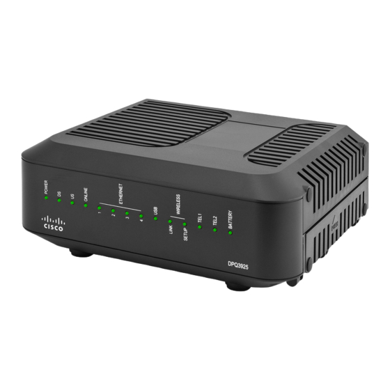
Page 17: Front Panel Description
Panel LED Status Indicator Functions (on page 102), for more information on front panel LED status indicator functions. Model DPQ3925 shown here POWER—ON, power is applied to the wireless residential gateway DS—ON, the wireless residential gateway is receiving data from the cable network US—On, the wireless residential gateway is sending data to the cable network... -
Page 18: Back Panel Description
Back Panel Description Back Panel Description The following illustrations show the description and function of the back panel components on the Cisco DPQ3925 residential gateway. LABEL—Displays technical information regarding the gateway MAC ADDRESS LABEL—Displays the MAC address of the residential gateway TELEPHONE 1 and 2—RJ-11 telephone ports connect to home telephone wiring to... -
Page 19: What Are The System Requirements For Internet Service
What Are the System Requirements for Internet Service? What Are the System Requirements for Internet Service? To ensure that your residential gateway operates efficiently for high-speed Internet service, verify that all of the Internet devices on your system meet or exceed the following minimum hardware and software requirements. -
Page 20: How Do I Subscribe To High-Speed Internet And Telephone Service
How Do I Subscribe to High-Speed Internet and Telephone Service? How Do I Subscribe to High-Speed Internet and Telephone Service? Before you can use your residential gateway, you need to have a high-speed Internet access account. If you do not have a high-speed Internet access account, you need to set up an account with your local service provider. - Page 21 How Do I Subscribe to High-Speed Internet and Telephone Service? I Already Have an Existing High-Speed Internet Access Account If you have an existing high-speed Internet access account, you must give your service provider the serial number and the MAC address of the residential gateway. Refer to the serial number and MAC address information listed previously in this section.
-
Page 22: Where Is The Best Location For My Docsis Residential Gateway
Where Is the Best Location for My DOCSIS Residential Gateway? Where Is the Best Location for My DOCSIS Residential Gateway? The ideal location for your residential gateway is where it has access to outlets and other devices. Think about the layout of your home or office, and consult with your service provider to select the best location for your residential gateway. -
Page 23: How Do I Mount The Modem On A Wall? (Optional)
How Do I Mount the Modem on a Wall? (Optional) How Do I Mount the Modem on a Wall? (Optional) You can mount the residential gateway on a wall using two wall anchors, two screws, and the mounting slots located on the unit. The modem can be mounted vertically or horizontally. - Page 24 How Do I Mount the Modem on a Wall? (Optional) Location and Dimensions of the Wall-Mounting Slots The following illustration shows the location and dimensions of the wall-mounting slots on the bottom of the modem. Use the information on this page as a guide for mounting your modem to the wall.
- Page 25 How Do I Mount the Modem on a Wall? (Optional) Mounting the Residential Gateway on a Wall Using a drill with a 3/16-inch bit, drill two holes at the same height and 4 inches apart. Note: The preceding graphic illustrates the location of the mounting holes on the back of the residential gateway.
-
Page 26: What Are The Requirements For Telephone Service
What Are the Requirements for Telephone Service? What Are the Requirements for Telephone Service? Number of Telephone Devices The RJ-11 telephone-style connectors on the residential gateway can each provide telephone service to multiple telephones, fax machines, and analog modems. The maximum number of telephone devices connected to each RJ-11 port is limited by the total Ringing Load of the telephone devices that are connected. -
Page 27: How Do I Connect My Gateway For Internet And Telephone Service
How Do I Connect My Gateway for Internet and Telephone Service? How Do I Connect My Gateway for Internet and Telephone Service? You can use your residential gateway to provide both telephone service and to provide Internet access, and you can share that Internet connection with other Internet devices in your home or office. - Page 28 How Do I Connect My Gateway for Internet and Telephone Service? WARNING: To avoid personal injury, follow the installation instructions in the exact order shown. To prevent possible damage to equipment, disconnect any other telephone service before connecting your cable modem to the same wires. ...
- Page 29 How Do I Connect My Gateway for Internet and Telephone Service? Connect one end of a telephone jumper cable (not included) to a telephone outlet in your home or to a telephone or fax machine. Then connect the other end of the jumper cable to the appropriate RJ-11 TELEPHONE port on the back of the residential gateway.
-
Page 30: How Do I Maintain The Battery? (Optional)
How Do I Maintain the Battery? (Optional) How Do I Maintain the Battery? (Optional) Your modem may include a rechargeable Lithium-Ion battery to provide stand-by operation in the event of an AC power failure. You can replace the battery without the use of any tools. - Page 31 How Do I Maintain the Battery? (Optional) Location of Battery As shown in the following illustrations, the battery compartment is located on the right side panel for both DPQ3925 housing types. Housing Ty pe 1 Housing Ty pe 2 Before Removing and Replacing the Battery Before removing and replacing the battery, refer to the following important information.
-
Page 32: How Do I Configure My Docsis Residential Gateway
How Do I Configure My DOCSIS Residential Gateway? How Do I Configure My DOCSIS Residential Gateway? To configure your residential gateway, you must first access the WebWizard configuration pages. This section provides detailed instructions and procedures for accessing the WebWizard pages and for configuring your residential gateway to operate correctly. - Page 33 How Do I Configure My DOCSIS Residential Gateway? In the address field, enter the following IP address: 192.168.0.1. A Status DOCSIS WAN login page similar to the following page opens. On the Status DOCSIS WAN page, leave the User Name and Password field blank and click Log In.
- Page 34 How Do I Configure My DOCSIS Residential Gateway? On the Administration Management page, create a User Name and Password and then click Save Settings. Once you save the settings for your User Name and Password on the Administration Management page, the Setup Quick Setup page opens.
- Page 35 How Do I Configure My DOCSIS Residential Gateway? Configuring Quick Settings Use the descriptions and instructions in the following table to configure the network settings for the device. After you make your selections, click Save Settings to apply your changes or click Cancel Changes to cancel. Section Field Description Change Password...
- Page 36 How Do I Configure My DOCSIS Residential Gateway? Section Field Description WLAN Wireless Network Allows you to enable or disable the wireless network. Select the desired option: Enable Disable Wireless Network Name (SSID) Allows you to enter a name for your wireless network or to use the default value.
- Page 37 How Do I Configure My DOCSIS Residential Gateway? Setup > Lan Setup The Setup Lan Setup page allows you to configure the settings for the Local Area Network (LAN) in your home. These settings include the range of IP addresses that define the LAN itself as well as how the addresses are assigned (automatically by DHCP or manually) as new devices are added to the network.
- Page 38 How Do I Configure My DOCSIS Residential Gateway? Section Field Description Network Address DHCP Server Server Settings Allows you to enable or disable the DHCP server in the (DHCP) residential gateway. The DHCP server is used to automatically allocate IP addresses to devices as they are attached to your home network.
- Page 39 How Do I Configure My DOCSIS Residential Gateway? Section Field Description Maximum Number of DHCP Users Enter the maximum number of users to which the DHCP server can assign IP addresses for use in the LAN. This number cannot be greater than 254 minus the starting IP address described above.
- Page 40 How Do I Configure My DOCSIS Residential Gateway? Section Field Description DDNS Disabling DDNS (Factory Default Settings) Service To disable DDNS, select Disabled from the drop-down list and click Save Settings. Enabling DDNS Note: In order to use the DDNS feature, you must first set up an account and establish a URL with www.DynDNS.org.
-
Page 41: Configure Wireless Settings
Configure Wireless Settings Configure Wireless Settings This section describes the options available from the Wireless pages that you can use to configure the parameters of the WAP to meet your specific requirements and needs. Wireless > Basic Settings Setting up your residential gateway for wireless communication provides you with the freedom to connect to the Internet from any location within range of the WAP without having to use wired connections. - Page 42 Configure Wireless Settings Wireless Configuration Wi-Fi Protected Setup Example Wireless Configuration Wi-Fi Protected Setup Page Description Use the descriptions and instructions in the following table to configure the basic settings for Wi-Fi Protected Setup for the residential gateway. After you make your selections, click Save Settings to apply your changes or Cancel Changes to cancel.
- Page 43 Configure Wireless Settings Section Field Description WPS Setup Using Your Wi-Fi Adapter PIN (Option 2) This is the most secure option to register a wireless client with the gateway. You need the Wi-Fi Protected Setup PIN number, which is found in the client Wi-Fi Protected Setup utility. After entering the client's Wi-Fi Protected Setup PIN number, you can then connect to the gateway.
- Page 44 Configure Wireless Settings Section Field Description Basic Settings Wireless Network Enable or Disable the wireless network Wireless Configuration The default is WPS. See Wi-Fi Protected Setup (WPS) (on page 41) for more information about using WPS. Select Manual to manually set up your network using this option. Network Mode Choose one of these options for the network mode: G only, B/G Mixed, B/G/N Mixed (factory default)
- Page 45 Configure Wireless Settings Section Field Description Wireless Network Name (SSID) The SSID is the name of your wireless network. The SSID is used by wireless technology to identify your network from other wireless networks in the area. The SSID can be up to 32 characters long. The factory default SSID is typically the last 6 characters of the CM MAC address found on the rating label located on the bottom of your gateway.
- Page 46 Configure Wireless Settings Wireless Security Page Description Use the descriptions and instructions in the following table to configure the wireless security for the residential gateway. After you make your selections, click Save Settings to apply your changes or Cancel Changes to cancel. Section Field Description Wireless...
- Page 47 Configure Wireless Settings Section Field Description Security for Personal Networks – WPA or WPA2 Personal Modes Wi-Fi Protected Access (WPA) is a more secure wireless technology than WEP. WPA can be used for both Enterprise (corporate applications) and Personal (home network) wireless networks. We strongly recommend that you select either WPA-Personal or WPA2-Personal as the security mode for your home network, depending on which mode is supported by the wireless adapter in your PC or wireless clients.
- Page 48 Configure Wireless Settings Section Field Description Security for Enterprise Networks - WPA-Enterprise Modes This option features WPA used in coordination with a RADIUS server for client authentication. (This should only be used when a RADIUS server is connected to the device.) Select from one of the following three WPA or WPA2 Enterprise modes: ...
- Page 49 Configure Wireless Settings Wireless > MAC Filter The MAC Filter feature is used to either allow or block access to your wireless LAN based on the MAC Address of the wireless client devices. The MAC Filter feature, also known as an access list, can be used to help protect your wireless network from access by unauthorized users.
- Page 50 Configure Wireless Settings Section Field Description Access Access Restriction Restriction Allows you to permit or block computers from accessing the wireless network. The choice that you make here affects the addresses listed on this page. Choose one of the following options: ...
- Page 51 Configure Wireless Settings Wireless Advanced Settings Page Description Use the descriptions and instructions in the following table to configure the advanced wireless settings for your residential gateway. After you make your selections, click Save Settings to apply your changes or Cancel Changes to cancel. OL-30 824-01...
- Page 52 Configure Wireless Settings Section Field Description Advanced N Transmission Rate Wireless The rate of data transmission should be set depending on the speed of your Wireless-N networking. Select from a range of transmission speeds, or select Auto to have the device automatically use the fastest possible data rate and enable the Auto-Fallback feature.
- Page 53 Configure Wireless Settings Section Field Description DTIM Interval The Delivery Traffic Indication Message (DTIM) indicates the interval between Broadcasts/Mul tica st transmissions. DTIM field is a countdown field informing clients of the next window for listening to broadcast and multicast messages. When the device has buffered broadcast or multicast messages for associated clients, it sends the next DTIM with a DTIM Interval value.
- Page 54 Configure Wireless Settings Wireless > WDS Settings The Wireless Distribution System (WDS) Settings page allows you to expand the coverage of your wireless network by deploying signal repeaters. Make sure the channel settings are the same for all WDS enabled devices. Select the WDS Settings tab to open the Wireless WDS Settings page.
- Page 55 Configure Wireless Settings Wireless > QoS Quality of Service (QoS) ensures better service to high-priority types of network traffic, which may involve demanding, real-time applications, such as video conferencing. QoS settings allow you to specify priorities for different types of traffic.
- Page 56 Configure Wireless Settings Section Field Description No ACK Allows you to enable or disable NO ACK. This feature is recommended for data services where transmission is important and packet loss is tolerable to a certain degree. If you select Disable, an acknowledge packet is returned for every packet received.
-
Page 57: Configure Security
Configure Security Configure Security Security > Firewall Advanced firewall technology deters hackers and protects the home network from unauthorized access. Use this page to configure a firewall that can filter out various types of unwanted traffic on the gateway’s local network. Select the Firewall tab to open the Security Firewall page. - Page 58 Configure Security Section Field Description Filters Filter Proxy Enables/disables filter proxy. If local users have access to WAN proxy servers, they may be able to circumvent the content filters and access Internet sites blocked by the device. If you select the Filter Proxy feature, it will block access to any WAN proxy servers.
- Page 59 Configure Security Security > VPN Passthrough Use this page to configure Virtual Private Network (VPN) support. Enabling the settings on this page allows VPN tunnels using IPsec or PPTP protocols to pass through the gateway's firewall. Select the VPN Passthrough tab to open the Security VPN Passthrough page.
- Page 60 Configure Security Security > VPN A Virtual Private Network (VPN) is a connection between two endpoints in different networks that allows private data to be sent securely over public networks or other private networks. This is accomplished by creating a "VPN tunnel." A VPN tunnel connects the two PCs or networks and allows data to be transmitted over the Internet as if it were on a private network.
- Page 61 Configure Security Security VPN Tunnel Page Description Use the descriptions and instructions in the following table to configure the VPN tunnel for your gateway. After you make your selections, click Save Settings to apply your changes or Cancel Changes to cancel. Section Field Description VPN Tunnel Select Tunnel Entry...
- Page 62 Configure Security Section Field Description Remote Select the desired option, IP Addr., Any, or FQDN. If the remote gateway has a Secure dynamic IP address, select Any or FQDN. If Any is selected, then the Gateway will Gateway accept requests from any IP address. FQDN If FQDN is selected, enter the domain name of the remote gateway, so the Gateway can locate a current IP address using DDNS...
- Page 63 Configure Security Section Field Description Select one of the following options for the key exchange method: Management Auto (IKE) (continued) – Encryption: The Encryption method determines the length of the key used to encrypt/decrypt ESP packets. Notice that both sides must use the same method.
- Page 64 Configure Security Section Field Description Status This field shows the connection status for the selected tunnel. The state is either Connected or Disconnected. Buttons Connect Click this button to establish a connection for the current VPN tunnel. If you have made any changes, click Save Settings to first apply your changes.
- Page 65 Configure Security View Log The Security VPN View Log page shows events captured by the firewall. The log displays the following items: Description of the event Number of events that have occurred Last occurrence of an event Target and source addresses ...
-
Page 66: Control Access To The Gateway
Control Access to the Gateway Control Access to the Gateway Access Restrictions > IP Address Filtering Use the Access Restrictions IP Filtering page to configure IP address filters. These filters block a range of IP addresses from accessing the Internet. Note: If you are not familiar with the advanced settings detailed in this section, contact your service provider before you attempt to change any of the residential gateway default advanced IP filtering settings. - Page 67 Control Access to the Gateway Select the MAC Address Filtering tab to open the Access Restrictions MAC Address Filtering page. The Block/Pass drop down menu allows you to block or pass Internet access to the MAC addresses of the devices you list in the MAC Address Filters table. The following table describes the function of the Block/Pass drop down menu.
- Page 68 Control Access to the Gateway Access Restrictions > Basic Rules Access restrictions allow you to block or allow specific kinds of Internet usage and traffic, such as Internet access, designated applications, websites, and inbound traffic during specific days and times. The Access Restrictions Basic Rules page allows you to configure parental controls on the residential gateway, and to monitor the individuals who are authorized to set parental controls.
- Page 69 Control Access to the Gateway Use the descriptions and instructions in the following table to configure the access restrictions basic rules for your residential gateway. After you make your selections, click Save Settings to apply your changes or Cancel Changes to cancel. Section Field Description Parental Control Basic...
- Page 70 Control Access to the Gateway Section Field Description Override the Password Password Allows you to create a password to temporarily override user access restrictions to a blocked Internet site Re-Enter Password Re-enter the same password for confirmation of the override password in the previous field Access Duration Allows you to designate an amount of time in minutes that the...
- Page 71 Control Access to the Gateway Use the Keyword List to enter the keywords you wish to block. If any of these keywords appears in the URL of a website, access to the site will be blocked. Note that only the URL is check, not the content of each webpage. Access Restrictions >...
- Page 72 Control Access to the Gateway Section Field Description Tod Filter Allows you to add a new Time of Day access filter or rule. Enter the name of the filter and click the Add key to add the filter to the list. Time of Day rules are used to restrict Internet access based on the day and time.
- Page 73 Control Access to the Gateway Access Restrictions User Setup Page Description Use the descriptions and instructions in the following table to configure the user setup for your residential gateway. After you make your selections, click Save Settings to apply your changes or Cancel Changes to cancel. Section Field Description User...
- Page 74 Control Access to the Gateway Section Field Description Inactivity Time 60 minutes [Factory default when a user is created. Otherwise, it is 0 (zero)]. Enter the amount of time during a user session where there is no Internet access activity, indicating that the user is no longer online.
-
Page 75: Configure Applications And Gaming
Configure Applications and Gaming Configure Applications and Gaming Overview Most well-known Internet applications are supported by Application Layer Gateways (ALGs). ALGs automatically adjust the gateway firewall to allow data to pass without making any custom settings. We recommend that you test your application before making changes in this section. - Page 76 Configure Applications and Gaming Section Field Description Port Filtering Start Port: This is the beginning of the port range. Enter the beginning of the range of port numbers (external ports) used by the server or Internet application. Check with the software documentation of the Internet application for more information if necessary.
- Page 77 Configure Applications and Gaming Applications and Gaming Port Range Forward Page Description Use the descriptions and instructions in the following table to configure the port range forwarding for the residential gateway. Select enable for each. After you make your selections, click Save Settings to apply your changes or Cancel Changes to cancel.
- Page 78 Configure Applications and Gaming Applications & Gaming > Port Range Triggering Port range triggering is a way to dynamically forward ports to a LAN PC that needs them at a particular time. That particular time is when it runs a certain application that performs some event that trigger the router.
- Page 79 Configure Applications and Gaming Section Field Description End Port For the End port, select a port from the recommended 49152 - 65535 range. Keep in mind that ports used are program specific so check which ones the program requires to be forwarded. Protocol Select one of the following protocols: ...
- Page 80 Configure Applications and Gaming Applications and Gaming DMZ Page Description Use the descriptions and instructions in the following table to configure the port range triggering for the residential gateway. Select enable for each DMZ Host IP address. After you make your selections, click Save Settings to apply your changes or Cancel Changes to cancel.
-
Page 81: Manage The Gateway
Manage the Gateway Manage the Gateway Administration > Management The Administration Management page allows the network’s administrator to manage specific gateway functions for access and security. Select the Management tab to open the Administration Management page. Important: The following page displays when DHCP (factory default) is the Connection Mode. - Page 82 Manage the Gateway Field Description Gateway Setup Connection Mode This setting allows you to determine how the (WAN) WAN (or gateway interface to the Internet) obtains its IP address. Internet Connection DHCP (factory default) Type Allows the gateway to obtain a public IP address automatically Static IP Allows you to specify the WAN IP address and corresponding server information as static or fixed values that will be used...
- Page 83 Manage the Gateway Field Description Internet IP Address Enter the gateway’s IP address (as seen from the Internet) Subnet Mask Enter the gateway’s subnet mask (as seen from the Internet, including your service provider) Default Gateway Enter the default gateway of the service provider’s server Primary DNS Enter the primary domain name server IP address(es) provided by your service provider.
- Page 84 Manage the Gateway Field Description Remote Access Remote Management Allows you to enable to disable remote management. This feature allows you to access and manage your gateway settings from the Internet when you are away from home. To allow remote access, select Enable.
- Page 85 Manage the Gateway Administration > Reporting Administration reporting allows you to email various system activities to your email address. Select the Reporting tab to open the Administration Reporting page. Use the descriptions and instructions in the following table to configure the reporting feature on the gateway.
-
Page 86: View Log
Manage the Gateway View Log To view the logs, complete the following steps. Click View Log. A new window opens with the log data page. To view a particular log, select one of the following options from the Type drop- down menu: ... - Page 87 Manage the Gateway Administration > Diagnostics Administration diagnostics allow you to check the status of your Internet connection by using a Ping test. Select the Diagnostics tab to open the Administration Diagnostics page. Use the descriptions and instructions in the following table to configure the diagnostics feature on the gateway.
- Page 88 Manage the Gateway Administration > Backup & Restore Administration Backup & Restore allows you to back up you configuration of the Gateway and store it on your computer. You can use this file to restore a previously saved configuration for your Gateway. Select the Back Up &...
-
Page 89: Restore Factory Defaults
Manage the Gateway Administration > Factory Defaults The Administration Factory Defaults page allows you to restore the configuration to its factory default settings. Select the Factory Defaults tab to open the Administration Factory Defaults page. CAUTION: If you restore the factory defaults, the gateway will lose all of the settings you have entered. -
Page 90: Monitor Gateway Status
Monitor Gateway Status Monitor Gateway Status This section describes the options available under the Status tab that you can use to monitor the status of the residential gateway and to perform diagnostics on the device and the network. Status > Gateway The Gateway Status page displays information about the gateway and its current settings. - Page 91 Monitor Gateway Status Section Field Description Internet Connection IP Address Displays the IP address of the WAN interface. This address is assigned to the gateway when it goes online. Subnet Mask Displays the subnet mask for your WAN port. This address is automatically assigned to your WAN port by your ISP except when a static IP address is set up.
- Page 92 Monitor Gateway Status Section Field Description A MAC address is a hardware address that uniquely identifies each node of a network. IP Address Displays the IP address for the LAN subnet Subnet Mask Displays the subnet mask for your LAN DHCP Server Displays the status of your local DHCP server (Enabled or Disabled) Starting IP Address...
- Page 93 Monitor Gateway Status ARP/RARP Table Click ARP/RARP Table to see a complete list of all devices that are connected to your network. To retrieve the most up-to-date information, click Refresh. To exit this page and return to the Local Network page, click Close. The following illustration shows an example of the ARP/RARP Table.
- Page 94 Monitor Gateway Status Status Wireless Page Description Use the following table to review the status of your wireless network. Section Field Description Wireless MAC Address Network Displays the MAC Address of your gateway's local wireless access point Radio Band Displays one of the following radio band frequencies currently in operation: ...
- Page 95 Monitor Gateway Status Status > DOCSIS WAN DOCSIS WAN Status displays information about the system of your cable modem. Select the DOCSIS WAN tab to open the Status DOCSIS WAN page. DOCSIS WAN Page Description Use the descriptions in the following table to review the status of your DOCSIS WAN network.
- Page 96 Monitor Gateway Status Section Field Description MAC Address (CM MAC Address) Displays the CM MAC Address. The CM MAC Address is a unique alphanumeric address for the cable modem coaxial interface, which is used to connect to the CMTS at the headend. A MAC address is a hardware address that uniquely identifies each node of a network.
-
Page 97: Frequently Asked Questions
Frequently Asked Questions Frequently Asked Questions Q. How Do I Configure TCP/IP Protocol? A. To configure TCP/IP protocol, you need to have an Ethernet Network Interface Card (NIC) with TCP/IP communications protocol installed on your system. TCP/IP is a communications protocol used to access the Internet. This section contains instructions for configuring TCP/IP on your Internet devices to operate with the residential gateway in Microsoft Windows or Macintosh environments. - Page 98 Frequently Asked Questions Select both Obtain an IP address automatically and Obtain DNS server address automatically in the Internet Protocol (TCP/IP) Properties window, and then click OK. Click Yes to restart your computer when the Local Network window opens. The computer restarts.
- Page 99 Frequently Asked Questions Renewing the IP Address on Windows 95, 98, 98SE, and ME Systems Click Start, and then click Run to open the Run window. Type winipcfg in the Open field, and click OK to execute the winipcfg command. The IP Configuration window opens. Click the down arrow to the right of the top field, and select the Ethernet adapter that is installed on your PC.
-
Page 100: Common Troubleshooting Issues
Frequently Asked Questions Q. How does the residential gateway connect to my computer? A. The residential gateway connects to the PC using a wireless connection or the 10/100/1000BASE-T Ethernet port on your PC. If you want to use an Ethernet interface, Ethernet cards available from your local PC or office supply retailer, or from your service provider. -
Page 101: Tips For Improved Performance
Tips for Improved Performance Tips for Improved Performance Check and Correct If your residential gateway does not perform as expected, the following tips may help. If you need further assistance, contact your service provider. Verify that the plug to your residential gateway AC power is properly inserted ... -
Page 102: Front Panel Led Status Indicator Functions
Front Panel LED Status Indicator Functions Front Panel LED Status Indicator Functions Initial Power Up, Calibration, and Registration (AC Power applied) The following chart illustrates the sequence of steps and the corresponding appearance of the residential gateway front panel LED status indicators during power up, calibration, and registration on the network when AC power is applied to the residential gateway. - Page 103 Front Panel LED Status Indicator Functions Front Panel LED Status Indicators During Initial Pow er Up, Calibration, and Registration Part 2, Telephone Registration Step Front Panel Indicator Data Network Requesting Request Restarting Voice Telephone Registration Telephone IP Telephone Service Registration Complete Address Provisioning...
- Page 104 Front Panel LED Status Indicator Functions Normal Operations (AC Power applied) The following chart illustrates the appearance of the residential gateway front panel LED status indicators during normal operations when AC power is applied to the gateway. Front Panel LED Status Indicators During Normal Conditions Front Panel Normal Operations Indicator...
-
Page 105: Special Conditions
Front Panel LED Status Indicator Functions Front Panel LED Status Indicators During Normal Conditions Front Panel Normal Operations Indicator BATTERY* On – When battery is charged Blinks – When battery charge is low Off – when there is no battery in the unit *Illuminates as described for units that include a battery. -
Page 106: Notices
Trademarks Cisco and the Cisco logo are trademarks or registered trademarks of Cisco and/or its affiliates in the U.S. and other countries. A listing of Cisco's trademarks can be found at www.cisco.c om/go/trademarks. DOCSIS is a registered trademark of Cable Television Laboratories, Inc. - Page 107 Notices Copyright © 2013 Cisco Systems, Inc. All rights reserved. Information in this publication is subject to change without notice. No part of this publication may be reproduced or transmitted in any form, by photocopy, microfilm, xerography, or any other means, or incorporated into any information retrieval system, electronic or mechanical, for any purpose, without the express permission of Cisco Systems, Inc.
- Page 108 Fax: +1-408 527-0883 This document includes various trademarks of Cisco Systems, Inc. Please see the Notices section of this document for a list of the Cisco Systems, Inc., trademarks used in this document. Product and service availability are subject to change without notice.