Tripp Lite NetCommander B072-008-1 Owner's Manual
8- and 16-port netcommander cat5 rackmount kvm switches
Hide thumbs
Also See for NetCommander B072-008-1:
- Owner's manual (24 pages) ,
- Quick reference manual (1 page) ,
- Owner's manual (32 pages)
Table of Contents
Advertisement
Quick Links
Download this manual
See also:
Owner's Manual
Owner's Manual
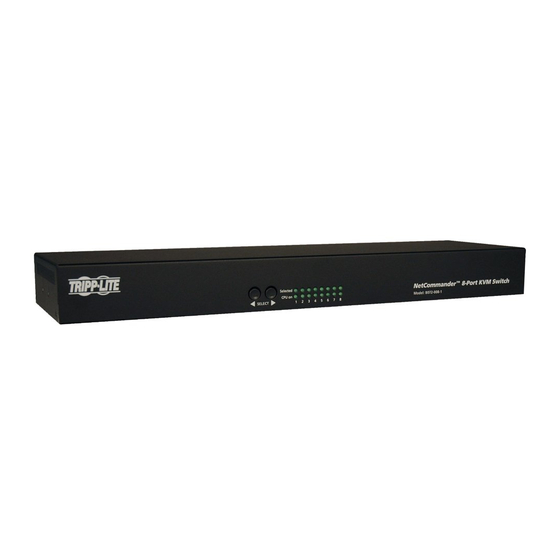
8- and 16-Port NetCommander™
Cat5 Rackmount KVM Switches
Models: B072-008-1 and B072-016-1
Note: Follow these installation and operating procedures to ensure correct performance and to prevent
damage to this unit or to its connected devices.
Tripp Lite World Headquarters
1111 W. 35th Street, Chicago, IL 60609 USA
www.tripplite.com/support
Copyright © 2011 Tripp Lite. All rights reserved. All trademarks are the property of their respective owners.
Advertisement
Table of Contents

Related Manuals for Tripp Lite NetCommander B072-008-1


Summary of Contents for Tripp Lite NetCommander B072-008-1
- Page 1 Note: Follow these installation and operating procedures to ensure correct performance and to prevent damage to this unit or to its connected devices. Tripp Lite World Headquarters 1111 W. 35th Street, Chicago, IL 60609 USA www.tripplite.com/support Copyright © 2011 Tripp Lite. All rights reserved. All trademarks are the property of their respective owners.
-
Page 2: Table Of Contents
Table of Contents 1. Features 6. Operation 2. System Components 6.1 Basic Operation 6.1.1 Pushbuttons 3. Compatibility 6.1.2 Keyboard Hotkeys 4. Configuration 6.1.3 On-Screen Display (OSD) 4.1 Front Panel 6.2 On-Screen Display (OSD) Functions 4.2 Back Panel 6.3 On-Screen Display (OSD F2 Settings 5. -
Page 3: Features
2. System Components • The NetCommander Cat5 KVM Switch consists of: • B072-008-1 (8-Port) or B072-016-1 (16-Port) Cat5 KVM Switch • Rackmount hardware • 1 serial download cable (DB9 Female to RJ11 Male) for firmware upgrade • C13 to 5-15P power cord • Owner’s Manual CD Accessories (available separately from Tripp Lite) include: • Server interface units (SIU)—PS/2 (model B078-101-PS2) or USB (model B078-101-USB) • Cat5e/6 cables (Tripp Lite model series: N001-, N002-, N201-, N202- or N105-) 3. Compatibility • The NetCommander Cat5 KVM Switch is compatible with: • PS/2 and USB computers/servers • Video resolutions up to 1600 x 1200 @ 75Hz • All major operating systems 4. -
Page 4: Back Panel
Reliable grounding of all rack-mounted equipment must be maintained. To protect against circuit overloading you should connect your Console KVM and attached computers/ servers to a Tripp Lite SmartPro ™ or SmartOnline ® UPS System. 5.2 Rackmounting the NetCommander KVM Use the L-shaped brackets and screws provided to mount the KVM in a server rack as illustrated below. -
Page 5: Connecting The Netcommander Kvm System
5. Installation ( continued ) 5.4 Connecting the NetCommander KVM System Connect each computer to the KVM using a Server Interface Unit (SIU) and Cat5e/6 patch cable. Figure 5.3 illustrates the connection options. NetCommander B072-016-1 KVM Switch Cat 5e/6 Cable Cat 5e/6 Cable Figure 5.4 NetCommander KVM system connections 5.5 NetCommander Server Interface Unit (SIU) The Server Interface Unit receives power from the connected computer. -
Page 6: Usb Server Interface Unit
5. Installation ( continued ) 5.5.2 USB Server Interface Unit Connecting a NetCommander USB Server Interface Unit (Model # B078-101-USB) 1. Connect the B078-101-USB VGA connector to the computers VGA port 2. Connect the B078-101-USB USB connector to the computers USB port 3. Connect one end of the Cat5e/6 patch cable to the RJ45 port on the B078-101-USB* 4. Connect the other end of the Cat5e/6 patch cable to the desired RJ45 CPU port* 5. Repeat these steps for each additional USB computer/server you are connecting to the KVM * Cat5e/6 cable should be no longer than 100 ft. -
Page 7: Cascading Netcommander Kvm Switches
5. Installation ( continued ) 5.8 Cascading NetCommander KVM Switches To cascade two or more NetCommander KVM Switches, follow the instructions below. You can connect up to 256 computers/servers in a complete 2-level installation. Note: The distance between the first- and second-level KVMs, and between the second-level KVMs and connected computers, cannot total more than 100 ft. -
Page 8: Operation
6. Operation 6.1 Basic Operation The NetCommander KVM Switch provides three methods for accessing connected computers; Pushbuttons, Keyboard Hotkeys and On-Screen Display (OSD). 6.1.1 Pushbuttons Press the pushbuttons on the front panel of the KVM to toggle between the connected computers. 6.1.2 Keyboard Hotkeys Keyboard hotkeys allow you to toggle between ports using the keyboard. -
Page 9: On-Screen Display
6. Operation ( continued ) F5 – TUNING As computers are located further away from the KVM switch, the video can become distorted. In the event you are experiencing poor video quality, the TUNING function can be used to correct it. Press the [F5] key to display the currently selected port, with the TUNING bar displayed. Use the [←] and [→] keys to make the necessary adjustments. When you are finished, press the [Esc] key to go back to the OSD. Note: Tuning is performed on a port-by-port basis. - Page 10 6. Operation ( continued ) 6.3 On-Screen Display (OSD) F2 SETTINGS ( continued ) Hotkey By default, the hotkey used in keyboard hotkey commands and to open the OSD is the [Shift] key, but this can be changed to any of the four options below. To toggle between commands, highlight the Hotkey option and press the [Spacebar] key.
-
Page 11: Ports
6. Operation ( continued ) 6.3 On-Screen Display (OSD) F2 SETTINGS ( continued ) 6.3.2 Ports Highlight the Ports option and press the [Enter] key to open the Port Settings page. This page allows you to edit port names, set the remote computer keyboard type, and set the hotkey for ports that have second level KVM switches connected to them. -
Page 12: Users
6. Operation ( continued ) 6.3 On-Screen Display (OSD) F2 SETTINGS ( continued ) 6.3.4 Users The Users option can only be accessed when Security is enabled in the General Settings page. (See General under On-Screen Display OSD F2 Settings section for details.) Highlight the Users option and press the [Enter] key to open the User Settings page. -
Page 13: Software
7.5 Current Firmware Verification After the physical connection is made, you must install the Firmware Upgrade Utility on the upgrade computer (the computer you just connected to the KVM) and then check the current firmware version on your KVM to see if it needs to be updated. To do this, follow the steps below. 1. On the upgrade computer, go to www.tripplite. com/support and download the latest firmware for the B072-008-1 or B072-016-1. The Firmware Upgrade Utility and KVM/SIU Firmware Upgrade File will be downloaded together. 2. Run the Firmware Upgrade Utility to install it on the upgrade computer. Follow the installation prompts to install the utility. - Page 14 7. Firmware Upgrade ( continued ) 7.5 Current Firmware Verification ( continued ) 3. When installation is complete, clicking the Finish button will automatically open the Firmware Upgrade Utility with the main screen displayed. Figure 7-2: Firmware Upgrade Utility Main Screen 4. There are three types of firmware to be verified; OSD, Manager and SIU. Start by checking the NetCommander CAT5 KVM Switch OSD box at the top of the utility, and then click the F/W Version button at the bottom of the utility to display the firmware version number. Check this against the firmware you downloaded from the Tripp Lite website to determine if an upgrade is needed.
- Page 15 6. Uncheck the NetCommander CAT5 KVM Switch Manager box, and check the box in the middle of the utility next to each SIU for which you want to verify the firmware. Click the F/W Version button at the bottom of the utility to display the firmware version number. Check this against the firmware you obtained from the Tripp Lite website to determine if an upgrade is needed. Figure 7.5: SIU Verification...
-
Page 16: Firmware Upgrade
7. Firmware Upgrade ( continued ) 7.6 Firmware Upgrade Once you have determined that your KVM and/or SIU(s) need to be upgraded, follow the steps below to install the new firmware. 1. In the Firmware Upgrade Utility main screen, open the Options drop-down menu at the top of the screen and select the Com Port option. Select the com port of the upgrade computer that the Firmware Upgrade Cable is connected to and click OK. -
Page 17: Troubleshooting
8. Troubleshooting Warning: Disconnect device from AC mains before service operation! When using Firmware Update software, you may get a Communication Error message. If a Communication Error message appears during the update procedure, do the following: 1. Ensure that the RS232 serial cable's RS232 connector is connected to the switch's communication port 2. -
Page 18: Specifications
Compatible with all major operating systems Optional External Mouse PS/2, Wheel mouse, Intellimouse, 5-button mouse Resolution 1600x1200@75Hz NetCommander KVM Models B072-016-1 or B072-008-1 Switch Dimensions - 8/16 port 17” x 5” x 1.7” (unit) Product - 3.7 lbs. Weight - 8/16 port Shipping - 5.5 lbs. -
Page 19: Warranty & Registration
12.1 1-Year Limited Warranty TRIPP LITE warrants its products to be free from defects in materials and workmanship for a period of one (1) year from the date of initial purchase. TRIPP LITE's obligation under this warranty is limited to repairing or replacing (at its sole option) any such defective products. - Page 20 Tripp Lite World Headquarters 1111 W. 35th Street, Chicago, IL 60609 USA www.tripplite.com/support...