Table of Contents
Advertisement
Instructions – Parts List
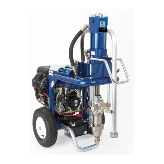
GH 733 Hydra–Spray
Sprayer
3500 psi (240 bar, 24 MPa) Maximum Working Pressure
Model 231733, Series E
Sprayer only. Has Severe-Duty* Displacement Pump
Model 230975
Includes Sprayer 231733, Hose, Swivel, Gun,
RACr X, DripLesst Tip Guard and SwitchTipt
*Severe-duty displacement pumps have an abrasion and corrosion-resistant displacement rod and
sleeve. Refer to the Technical Data in manual 311762.
Important Safety Instructions
Read all warnings and instructions in this manual.
Save these instructions.
GRACO INC. P.O. BOX 1441 MINNEAPOLIS, MN 55440–1441
Copyright 2002, Graco Inc. is registered to I.S. EN ISO 9001
r
307616Z1
9089c
Advertisement
Table of Contents

Related Manuals for Graco HydraSprayr 230975


Summary of Contents for Graco HydraSprayr 230975
- Page 1 Instructions – Parts List GH 733 Hydra–Spray Sprayer 3500 psi (240 bar, 24 MPa) Maximum Working Pressure Model 231733, Series E Sprayer only. Has Severe-Duty* Displacement Pump Model 230975 Includes Sprayer 231733, Hose, Swivel, Gun, RACr X, DripLesst Tip Guard and SwitchTipt *Severe-duty displacement pumps have an abrasion and corrosion-resistant displacement rod and sleeve.
-
Page 2: Table Of Contents
Warnings ........Component Identification . -
Page 3: Warnings
SKIN INJECTION HAZARD Spray from the gun, leaks or ruptured components can inject fluid into your body and cause extremely serious injury, including the need for amputation. Fluid splashed in the eyes or on the skin can also cause serious injury. D Fluid injected into the skin may look like just a cut, but it is a serious injury. -
Page 4: Fire And Explosion Hazard
FIRE AND EXPLOSION HAZARD Improper grounding, poor ventilation, open flames or sparks can cause a hazardous condition and result in a fire or explosion and serious injury. D If there is any static sparking or you feel an electric shock while using this equipment, stop spray- ing immediately. -
Page 5: Component Identification
Component Identification HYDRAULIC RETURN LINE TO MOTOR MOTOR RESET BUTTON HYDRAULIC MOTOR SUCTION TUBE OUTLET FITTING PRESSURE DRAIN VALVE DISPLACEMENT PUMP SUCTION HOSE Fig 1 1. Connect the Hose and Gun a. Remove the plastic cap plug from the outlet tee and screw an accessory, conductive or grounded spray hose onto the 1/4 npsm(f) out- let fitting. - Page 6 3. Check the Hydraulic Oil Level a. Unscrew the hydraulic oil fill cap. See Fig 2. The dipstick is attached to the cap. The oil should be up to the full line on the dipstick. CAUTION To prevent damage to the cooling system and hydraulic pump, use only Graco Hydraulic Oil, 169236 (5 gal./20 liter) or 207428 (1 gal/3.8 liter).
- Page 7 5. Fill the Fuel Tank WARNING FIRE AND EXPLOSION HAZARD Fuel spilled on a hot surface can cause a fire or explosion and serious bodily injury and property damage. Shut off engine and let it cool before filling the tank. Carefully follow steps 5.a. to 5.c., below, being sure not to spill any fuel.
-
Page 8: Flushing
When to Flush 1. New sprayer. Your new sprayer was factory tested with lightweight oil which was left in to protect pump parts from corrosion. Before using oil–base paint, flush with mineral spirits only. Before using water–base paint, flush with mineral spirits, followed by soapy water, then a clean water rinse. - Page 9 WARNING FIRE AND EXPLOSION HAZARD To reduce the risk of static sparking and splashing when flushing, always remove the spray tip from the gun and hold a metal part of the gun firmly to the side of a grounded metal pail. 11.
-
Page 10: Operation
Pressure Relief Procedure WARNING SKIN INJECTION HAZARD The system pressure must be manually relieved to prevent the system from starting or spraying accidentally. Fluid under high pressure can be injected through the skin and cause serious injury. To reduce the risk of an injury from injection, splashing fluid, or moving parts, follow the Pressure Relief Procedure whenever you:... - Page 11 If the motor stalls during operation, turn OFF the igni- tion key. With your hand, firmly press straight down on the motor reset button. Now try to restart the sprayer. If it will not start, refer to the separate motor manual, 307158.
-
Page 12: Maintenance
1. Always stop the pump at the bottom of its stroke when you take a break and at the end of the day. This helps keep fluid from drying on the rod and damaging the packings. 2. Keep the displacement pump packing nut/wet cup 1/3 full of TSL at all times. -
Page 13: Troubleshooting
WARNING SKIN INJECTION HAZARD To reduce the risk of serious injury, whenever you are instructed to relieve pressure, follow the Pressure Relief Procedure on page 10. Check everything in the troubleshooting chart before disassembling the sprayer. PROBLEM CAUSE Gas engine doesn’t work properly. Gas engine will not start. - Page 14 Replacing the Hydraulic Pump 1. Follow the Pressure Relief Procedure Warning on page 10. Let the hydraulic system cool before beginning the service procedure. 2. Unscrew the reservoir drain plug (51), having a container ready to catch the draining fluid. 3.
- Page 15 Replacing the Cooler and Blower 1. Follow the Pressure Relief Procedure Warning on page 10. Let the hydraulic system cool before beginning the service procedure. 2. Remove the hydraulic pump as instructed in the previous section. 3. Disconnect the cooler to reservoir return hose (7.) by loosening the hose clamp (8).
-
Page 16: Displacement Pump Service
Displacement Pump Service Disconnect the Displacement Pump 1. Flush the pump if possible. Stop the pump on the down stroke. 2. Follow the Pressure Relief Procedure Warning on page 10. 3. Remove the suction tube and fluid hose from the displacement pump. -
Page 17: Complete Sprayer Parts Drawing
Complete Sprayer Parts Drawing Model 230975, GH 733 Sprayer Includes items 501 to 510 NO. PART NO. DESCRIPTION 231733 GH 733 SPRAYER (See parts list on page 19) 218659 HOSE & GUN KIT, includes items 504 to 509 H53850 .HOSE, fluid, nylon, 3/8 in. ID, 3/8 npsm(fbe);... -
Page 18: Gh733 Sprayer Parts Drawing
GH733 Sprayer Parts Drawing Model 231733, Series D 307616 See page 17 for continuation 9086B... - Page 19 GH733 Sprayer Parts Drawing LABEL LABEL Ref 58 To Starter To Engine Switch LABEL LABEL LABEL LABEL 7877c 307616 LABEL LABEL...
- Page 20 GH733 Sprayer Parts Drawing Ref 77 307616 Ref 22 Ref 111 7879b 7879A...
-
Page 21: Gh733 Sprayer Parts List
NO. PART NO. DESCRIPTION 107074 BREATHER, fill cap 106114 STRAINER, inlet 107053 ELBOW, pipe, 90_, 1/2 x 3/8 npt 107128 TEE, service 107050 INSERT, hose, 1/2 npt(f) 178859 HOSE, rubber, 5 in. (125 mm) 102473 CLAMP, hose 210658 VALVE, ball 3/8 npt(m) 165472 ELBOW, pipe, 90_, 3/8 npt(f) 106039... - Page 22 Notes 307616...
-
Page 23: Accessories
Technical Data Engine ....KOHLER Model CH18 OHV 4 cycle twin cylinder, air cooled, 18 HP, (13.4 kW) Gasoline ....6.0 gallon (22.7 liter capacity) consumes 1.3 gal/hr (4.9 liter/hr) Hydraulic Fluid Sump... -
Page 24: Graco Phone Number
Graco Warranty Graco warrants all equipment listed in this manual which is manufactured by Graco and bearing its name to be free from defects in material and workmanship on the date of sale to the original purchaser for use. With the exception of any special extended or limited warranty published by Graco, Graco will, for a period of twelve months from the date of sale, repair or replace any part of the equipment determined by Graco to be defective.