Table of Contents
Advertisement
ALPINE ELECTRONICS, INC.
Tokyo office: 1-1-8 Nishi Gotanda,
Shinagawa-ku, Tokyo 141-8501, Japan
Tel.: (03) 3494-1101
ALPINE ELECTRONICS OF AMERICA, INC.
19145 Gramercy Place, Torrance,
California 90501, U.S.A.
Tel.: 1-800-ALPINE-1 (1-800-257-4631)
ALPINE ELECTRONICS OF CANADA, INC.
7300 Warden Ave., Suite 203, Markham,
Ontario L3R 9Z6, Canada
Tel.: 1-800-ALPINE-1 (1-800-257-4631)
Kukje Printing Co., Ltd
127-2 Gamjeon-dong
Sasang-gu
Busan Korea
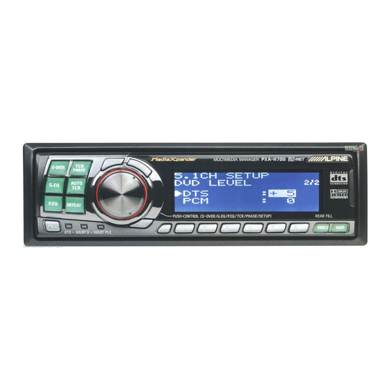
PXA-H700
MULTIMEDIA MANAGER™
• OWNER'S MANUAL
Please read before using this equipment.
• BEDIENUNGSANLEITUNG
Lesen Sie diese Bedienungsanleitung bitte vor
Gebrauch des Gerätes.
• MODE D'EMPLOI
Veuillez lire avant d'utiliser cet appareil.
• MANUAL DE OPERACIÓN
Léalo antes de utilizar este equipo.
• ISTRUZIONI PER L'USO
Si prega di leggere prima di utilizzare il
attrezzatura.
• ANVÄNDARHANDLEDNING
Innan du använder utrustningen bör du läsa
igenom denna användarhandledning.
ALPINE ELECTRONICS OF AUSTRALIA PTY. LTD.
6-8 Fiveways Boulevarde Keysborough,
Victoria 3173, Australia
Tel.: (03) 9769-0000
ALPINE ELECTRONICS GmbH
Kreuzerkamp 7, 40878 Ratingen,
Tel.: 02102-45 50
ALPINE ITALIA S.p.A.
Viale C. Colombo 8,
20090 Trezzano Sul Naviglio (MI), Italy
Tel.: 02-48 47 81
®
Germany
R
ALPINE ELECTRONICS FRANCE S.A.R.L.
(RCS PONTOISE B 338 101 280)
98, Rue de la Belle Etoile, Z.I. Paris
Nord II, B.P. 50016, 95945, Roissy
Charles de Gaulle Cedex, France
Tel.: 01-48 63 89 89
ALPINE ELECTRONICS OF U.K., LTD.
13 Tanners Drive, Blakelands,
Milton Keynes MK14 5BU, U.K.
Tel.: 01908-61 15 56
ALPINE ELECTRONICS DE ESPAÑA, S.A.
Portal de Gamarra 36, Pabellón, 32
01013 Vitoria (Alava) - APDO 133,
Spain
Tel.: 945-283588
Designed by ALPINE Japan
Printed in Korea (S)
68P02294K33-A
EN
DE
FR
ES
ES
IT
IT
SE
SE
Advertisement
Table of Contents

Related Manuals for Alpine MULTIMEDIA MANAGER PXA-H700


Summary of Contents for Alpine MULTIMEDIA MANAGER PXA-H700
- Page 1 • ANVÄNDARHANDLEDNING Innan du använder utrustningen bör du läsa igenom denna användarhandledning. ® ALPINE ELECTRONICS, INC. ALPINE ELECTRONICS OF AUSTRALIA PTY. LTD. ALPINE ELECTRONICS FRANCE S.A.R.L. Tokyo office: 1-1-8 Nishi Gotanda, 6-8 Fiveways Boulevarde Keysborough, (RCS PONTOISE B 338 101 280)
-
Page 3: Table Of Contents
ENGLISH Contents Using Dolby Surround Using the Pro Logic II mode ......... 20 Adjustment procedure for Dolby Surround ....21 Operating Instructions Speaker setup ..............22 Adjusting the speaker levels .......... 22 WARNING Mixing bass sound to the rear channel ......23 Adjusting the acoustic image ......... -
Page 4: Warning
DO NOT OPERATE ANY FUNCTION THAT TAKES YOUR ATTENTION AWAY FROM SAFELY DRIVING Failure to do so may cause personal injury or damage to the product. Return it to your authorized Alpine dealer or YOUR VEHICLE. the nearest Alpine Service Center for repairing. -
Page 5: Precautions
Be sure the temperature inside the vehicle is between +60 C (+140 F) and –10 C (+14 F) before turning your unit on. Installation Location Make sure the PXA-H700 will not be installed in a location subjected to: • Direct sun and heat • High humidity and water •... -
Page 6: Basic Operation
Basic Operation Setting the speakers First make the speaker settings. CHANNEL Turn off speaker channels that are not ENTER connected. Press the SETUP button. The setup mode is set. Turn the Rotary encoder to select the SETUP “SPEAKER SELECT” mode, then press the Rotary encoder ENTER button. -
Page 7: Using With Ai-Net Connections
Sub.W LEVEL system called “Ai-NET” which can only be used for connections between Ai-NET products. The PXA-H700 is an Ai-NET product, but is designed to Turn the Rotary encoder within 5 seconds and allow connections to other (non Ai-NET) products as adjust to the desired level. -
Page 8: Automatic Adjustments
Automatic Adjustments 2) Connect the microphone to the PXA-H700. AUTO TCR Base unit ENTER To microphone input jack Microphone Rotary encoder Set the vehicle’s engine key to the ACC position. • Vibrations could make it difficult to achieve the appropriate adjustment values, so turn the engine off. - Page 9 • If the microphone does not pick up the sound or the speakers are not working or are connected or wired improperly, the automatic adjustments are not performed and a error message is displayed. Check the various speakers then perform the automatic adjustments again.
-
Page 10: Settings/Adjustments
Settings/Adjustments • Concrete examples 1.Calculating the time correction value for the TCR/PHASE front left speaker on the diagram below. CHANNEL ENTER Conditions: Distance between farthest speaker and listening position: 2.25 m (88-3/4") Distance between front left speaker and listening position: 0.5 m (20") Calculation: L = 2.25 m (88-3/4") –... - Page 11 Turn the Rotary encoder to switch the phase, Press and hold the CHANNEL button for at least then press the CHANNEL button. 2 seconds and select “L and R (LR)” or “L or R”. Press the ENTER button to return to step 8. L and R (LR) L or R (factory default)
-
Page 12: Bass Focus
Settings/Adjustments Turn the Rotary encoder to set the step of front- rear/left-right. TCR/PHASE Moreover, for setting another channel (speaker), CHANNEL repeat steps 4 and 5. ENTER After completing the setting, press the ENTER button to return to the time correction mode. Here, you can compare the sound of Defeat OFF (adjustment value) and Defeat ON (initial). - Page 13 Time difference Table Example of Steps 4 and 5 Setting 1.After entering corrections for the front (left and Number Time Number Time Number Time right) speakers in STEP 30, the time difference Difference Difference Difference is 1.5 ms for both front-left and front-right steps (ms) steps...
-
Page 14: Graphic Equalizer Adjustments
Settings/Adjustments *1 When center is set to subwoofer, it is not displayed. *2 When center is set to subwoofer, it becomes Sub.W(L). G.EQ CHANNEL *3 When center is set to subwoofer, it becomes ENTER Sub.W(R). Turn the Rotary encoder to select the frequency, then press the ENTER button. -
Page 15: Parametric Equalizer Adjustments
Turn the Rotary encoder to select the Parametric equalizer adjustments frequency, then press the ENTER button. For the adjustable frequencies, see page 43. The frequency bands of the graphic equalizer are fixed. This makes it very difficult to correct for undesired peaks and dips at specific frequencies. - Page 16 Settings/Adjustments NOTES • When the speaker is set to the “OFF” mode, the parametric equalizer for that speaker is ineffective. Refer to “Setting the speakers” (page 4). • It is not possible to adjust the frequencies of adjacent CHANNEL bands within 7 steps. ENTER •...
-
Page 17: X-Over
X-OVER Signals with these frequencies output The PXA-H700 is equipped with an active Slope OFF crossover allowing the frequency bands to be Slope adjustment split before amplification. Because of this, there is no need for a passive network between the speakers and amplifiers. -
Page 18: X-Over Adjustment
Settings/Adjustments Turn the Rotary encoder to adjust the H.P.F. cutoff frequency, then press the ENTER button. The adjustable bands differ according to the X-OVER channel (speaker). CHANNEL ENTER X – O F r o n t 2 1/2 3 5 0 H P s l o p L P f... - Page 19 Hint for adjusting the subwoofer • If the subwoofer is installed on the rear deck, setting a gentle L.P.F. slope (for example 6 dB/ oct.) makes the sound localization more to the rear. This can also affect the acoustic localization of the front. Hints for adjusting the high range •...
-
Page 20: Mx Settings
In case of “MX OFF”, press and hold the MX (page 27) is set to “Manual”. button for at least 2 seconds to turn the MX In these cases, the PXA-H700 is not interlocked mode on. with the head unit, therefore it is necessary to set... -
Page 21: Bass Comp. Setting
Turn the Rotary encoder to select the source (media) you want to set, then press the ENTER button. Turn the Rotary encoder to select the desired mode, then press the ENTER button. For further information about setting mode, see step 3 of 1 (page 18). To set other sources (media), press the MX button and return to step 3. -
Page 22: Using Dolby Surround
Using the Pro Logic II mode center channel position between the center speaker and the L/R speaker. With the PXA-H700, Pro Logic processing can be 3) Turn the Rotary encoder to adjust the level, conducted on the music signals recorded on two then press the ENTER button. -
Page 23: Adjustment Procedure For Dolby Surround
(Adjust the volume (signal level) in the Dolby Digital, Pro Logic II, DTS and PCM modes.) Storing settings in the memory (page 28) (Storing all the settings and adjustments made on the PXA-H700 (not only the above settings/adjusts) in the memory) NOTE In case of combining the Automatic adjustments etc. -
Page 24: Speaker Setup
Speaker setup NOTES • If the center speaker is turned "OFF", the center The PXA-H700 can be set according to the channel's audio signals are added to the audio playable frequency range of your speakers. signals output from the front speakers. -
Page 25: Mixing Bass Sound To The Rear Channel
Turn the Rotary encoder to select “Auto”, then Mixing bass sound to the rear channel press the ENTER button. Test tone output is repeated for each of the different speaker This function mixes the front channel audio channels. They will be repeated in the order signals to the audio signals output from the rear shown below. -
Page 26: Adjusting The Acoustic Image
Using Dolby Surround Turn the Rotary encoder to adjust the level, then press the ENTER button. The level can be adjusted within the range of –5 to +5. The higher the level, the more the position of the center speaker is shifted to the sides. ENTER Once the settings are completed, press the SETUP button repeatedly to quit the setup... -
Page 27: Achieving Powerful High Volume Sound
Achieving powerful high volume sound Adjusting the DVD level With Dolby Digital, the dynamic range is The volume (signal level) for the Dolby Digital, compressed so that powerful sound can be Pro Logic II, DTS and PCM modes can be set. achieved at regular volume levels. -
Page 28: Convenient Functions
When the navigation system is connected, make or “3ch Output”, then press the ENTER button. the navigation system’s voice guidance messages to interrupt the PXA-H700, then 2ch Output: 2ch output (L/R) output from the front speaker. 3ch Output: 3ch output (L/R/CENTER) Press the SETUP button repeatedly to quit the Press the SETUP button. -
Page 29: Display Settings
Display settings MX mode setting (Ai-NET connection) The display’s contrast and LCD (negative/ Use this setting when using the PXA-H700 in positive) can be adjusted. combination with an Ai-NET head unit equipped with the automatic MX mode selection function (for example, DVA-7996R). -
Page 30: Storing Settings In The Memory
This operation can only be performed when the defeat mode is turned off. Up to six adjustments and settings can be stored in the PXA-H700’s memory. Defeat mode Press the DEFEAT button. Make the adjustment or setting you want to store All properties are made flat. -
Page 31: Switching The Display Mode
Switching the color of the illumination Switching the display mode Press the DISP button to select the desired The color of the PXA-H700’s switch illumination display mode. can be changed. Spectrum analyzer display(1~3) Input channel display Display OFF Press and hold the DISP button for at least 2 seconds and select the desired color. -
Page 32: Installation And Connections
Installation and Connections Before installing or connecting the unit, please DO NOT USE BOLTS OR NUTS IN THE BRAKE OR read the following and pages 2 and 3 of this STEERING SYSTEMS TO MAKE GROUND manual thoroughly for proper use. CONNECTIONS. -
Page 33: Precautions
When connecting the this unit may result in product failure. PXA-H700 to the fuse box, make sure the fuse for the intended circuit of the PXA-H700 has the appropriate amperage. Failure to do so may result in damage to the unit and/or the vehicle. -
Page 34: Accessories
(M2.6 x 8) far away from the unit as possible. Your Alpine dealer carries various noise suppressors. Contact them for further information. • Your Alpine dealer knows best about noise prevention measures so consult your dealer for further 1 set information. -
Page 35: Installation
Mount the control unit using the included screws. Installation Bracket The PXA-H700 is made up of two components: the Spacer Control Unit and Base Unit. Mounting the control unit Control unit CAUTION: Pan head screw Do not install the control unit near the air-bag of the (M3 x 5) x 2 front passenger’s seat. - Page 36 Installation and Connections Mount the spacer and bracket to the control unit. Mount the spacer on the control unit using the Next, securely mount the factory brackets included screws. removed from the factory radio, to the control Spacer unit assembly. Flat head screws (M5 x 8) Control unit Pan head screw...
- Page 37 Using the Mounting Screws (Supplied) Mounting the base unit The Base Unit can be mounted under the seat Velcro Fastener Mounting using the mounting screws. Decide on the installation location. • The trunk, etc., is the best place. Mark the positions of the mounting screws at the chosen location.
-
Page 38: Basic Connections Diagram
Used to interrupt the navigation system’s sound. Fuse • Battery power cable Connect this lead to the positive(+) post of Power is supplied constantly to the PXA-H700 regardless Yellow (3A) the vehicle's battery. of whether the engine key is on or off. -
Page 39: Examples Of System Expansion
Examples of system expansion • PXA-H700 + Ai-NET Compatible Head Unit + DVD Changer + Monitor + External Amplifier Fiber Optic Cable (Sold Separately) Remote Control Input Cable Remote Control Output Cable Monitor (White/Brown) (White/Brown) (TME-M790 etc.) To Video Input Jack... - Page 40 Installation and Connections • PXA-H700 + Ai-NET Compatible Head Unit + CD Changer + External Amplifier Fiber Optic Cable (Sold Separately) Fiber Optic Cable (Sold Separately) Ai-NET Cable (Included with CD Changer) Ai-NET Compatible Ai-NET Cable (Included) CD Changer Ai-NET Compatible...
- Page 41 The PXA-H700 can then be turned on using this switch. The PXA-H700 can be used with any head unit. However, only an Alpine Ai-NET compatible head unit will be able to take full advantage of all the features and functions of this processor.
- Page 42 Installation and Connections • PXA-H700 + DVA-7996R Head Unit + CD Changer + Navigation System + Monitor + External Amplifier White/Green White/Green Guide Control Cable Guide Control Cable NTSC VIDEO OUTPUT NAVIGATION Navigation INPUT NTSC VIDEO GUIDE OUTPUT OUTPUT RGB OUTPUT...
-
Page 43: Information De
Information Dolby Pro Logic II Terminology Dolby Pro Logic II provides multichannel surround sound from any 2 channel source. It reproduces Dolby Digital extended bandwidth playback with 5.1 channels. Dolby Digital is a digital audio compression This is made possible by an advanced matrix technology developed by Dolby Laboratories that surround decoder. -
Page 44: Others
Otherwise, these adjustments cannot be made when they are make sure the rest of your system is properly connected to the PXA-H700. connected or consult your authorized Alpine dealer. Set does not operate. Nothing appears on the display. •... -
Page 45: Specifications
<Components> Specifications Parts name Quantity Graphic EQ number of bands: Parts for mounting ........ 1set Front (left and right) 31 bands Rear (left and right) 31 bands Owner’s manual ........1set Center 31 bands Microphone ........... 1set Subwoofer 10 bands Graphic EQ boost cut range: 9 dB... - Page 47 Händlerstemple Tipps der Polizei: Stellen Sie Ihr Fahrzeug stets gut sichtbar ab. Verschließen Sie Türen, Fenster, Schiebedach und Kofferraum immer, auch bei nur kurzer Abwesenheit. Lassen Sie keine Wertsachen sichtbar im Auto liegen. Wird Ihr Fahrzeug aufgebrochen, wenden Sie sich sofort an die nächste Polizeidienststelle. Belassen Sie Ihr Fahrzeug nach einem Aufbruch im Originalzustand.
- Page 48 Car Audio and Navigation Systems GERÄTE-PASS AUDIO SYSTEME Fahrzeugmarke: Typ: Amtl. Kennzeichen: Name des Halters: Straße: Wohnort: Bitte füllen Sie diesen Pass vollständig aus und bewahren Sie ihn außerhalb des Fahrzeugs auf: Im Falle eines Diebstahls wird für Sie die Schadensabwicklung mit der Versicherung einfacher, und Sie erleichtern der Polizei die Fahndung nach den Tätern.