Table of Contents
Advertisement
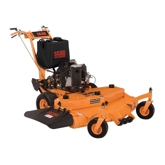
SW
Walk-Behind
Model:
SW32-14FS
SW36A-14FS
SW48V-14FS
SW52V-15FS
Congratulations on owning a Scag mower! This manual contains the operating
instructions and safety information for your Scag mower. Reading this manual
can provide you with assistance in maintenance and adjustment procedures to
keep your mower performing to maximum efficiency. The specific models that
this book covers are listed on the inside cover. Before operating your machine,
please read all the information enclosed.
© 2013
Scag Power Equipment
Division of Metalcraft of Mayville, Inc.
OPERATOR'S
MANUAL
PART NO. 03355
PRINTED 9/2013
PRINTED IN USA
Advertisement
Table of Contents

Related Manuals for Scag Power Equipment SW32-14FS


Summary of Contents for Scag Power Equipment SW32-14FS
- Page 1 SW36A-14FS SW48V-14FS SW52V-15FS Congratulations on owning a Scag mower! This manual contains the operating instructions and safety information for your Scag mower. Reading this manual can provide you with assistance in maintenance and adjustment procedures to keep your mower performing to maximum efficiency. The specific models that this book covers are listed on the inside cover.
- Page 2 CONCERN, PRUDENCE, AND PROPER TRAINING OF THE PERSONNEL INvOLvED IN THE OPERATION, TRANSPORT, MAINTENANCE, AND STORAGE OF THE EqUIPMENT. This manual covers the operating instructions and illustrated parts list for: SW32-14FS with a serial number of J6000001 to J6099999 SW36A-14FS...
-
Page 3: Table Of Contents
Table of Contents Table of Contents SECTION 1 - GENERAL INFORMATION ...................1 1.1 INTRODUCTION ............................1 1.2 DIRECTION REFERENCE ...........................1 1.3 SERvICING THE ENGINE AND DRIvE TRAIN COMPONENTS ..............1 1.4 SYMBOLS ..............................2 SECTION 2 - SAFETY INFORMATION ..................3 2.1 INTRODUCTION ............................3 2.2 SIGNAL WORDS ............................3 2.3 BEFORE OPERATION CONSIDERATIONS ....................3 2.4 OPERATION CONSIDERATIONS ........................4... - Page 4 7.6 CUTTER BLADES ............................27 7.7 TIRES ................................28 SECTION 8 - ILLUSTRATED PARTS LIST ................29 8.1 SCAG APPROvED ATTACHMENTS AND ACCESSORIES..............29 32" & 36A CUTTER DECkS ..........................30 48v & 52v CUTTER DECkS ...........................32 NOTES ................................34 CASTER ASSEMBLY ............................35 ENGINE DECk ..............................36 HANDLE ASSEMBLY............................38...
-
Page 5: General Information
We encourage you to contact your dealer for repairs. All Scag dealers are informed of the latest methods to open or removed. Under no circumstances should service this equipment and provide prompt and efficient your mower be operated without these devices service in the field or at their service shop. -
Page 6: Symbols
Section 1 SYMBOLS SYMBOL DESCRIPTION SYMBOL DESCRIPTION Choke Transmission Parking Brake Spinning Blade 48071S On/Start Spring Tension on Idler Off/Stop Falling Hazard Thrown Object Hazard Fast Slow Continuously Variable - Linear Cutting Element - Basic Symbol Pinch Point Cutting Element - Engage 481039S Hour meter/Elapsed Operating Hours Cutting Element - Disengage... -
Page 7: Safety Information
Scag Service Dealer or by contacting Scag Power Equipment, Service Department at P.O. Box 152, Mayville, WI 53050 or contact us via the Internet at www.scag.com. The manual for this machine can be downloaded by using The signal word “CAUTION” is a reminder of safety practices... -
Page 8: Operation Considerations
Section 2 If the operator(s) or mechanic(s) cannot read English Keep flammable objects (cigarettes, matches, etc.), or Spanish, it is the owner's responsibility to explain open flames and sparks away from the fuel tank and this material to them. fuel container. Use only approved containers. DO NOT wear loose fitting clothing. -
Page 9: Maintenance Considerations & Storage
Section 2 WARNING DANGER DO NOT use your hand to dislodge the clogged DO NOT run the engine inside a building or discharge chute. Use a stick or other device to a confined area without proper ventilation. remove clogged material after the engine has Exhaust fumes are hazardous and contain stopped running and the blades have stopped carbon monoxide which can cause brain injury... -
Page 10: Using A Spark Arrestor
Section 2 Keep all nuts, bolts and screws tight, to ensure the machine is in safe working condition. Check blade mounting bolts frequently to be sure they are tight. Do not change the engine governor settings or overspeed the engine. See the engine operator's manual for information on engine settings. -
Page 11: Safety And Instructional Decals
*Read oper at or ' s m anual *Sol i ci t e et i quet as en es panol a un di s t r i bui dor Scag *M ake s ur e guar ds , s hi el ds &... -
Page 12: Specifications
SPECIFICATIONS ENGINE General Type ....................Heavy Duty Industrial/Commercial Gasoline Brand ..................................Kawasaki Engine Model: (Scag Model SW32-14FS, SW36A-14FS, SW48V-14FS) ..........Kawasaki Model # FS481V (Scag Model SW52V-15FS) ....................Kawasaki Model # FS541V Displacement: Kawasaki FS481V .............................. 603cc Kawasaki FS541V .............................. 603cc Cylinders ........................2 with Cast-Iron Sleeves - Kawasaki Governor ..........Mechanical Type with Variable Speed Control Set At 3600 RPM (+/- 100 RPM) -
Page 13: Cutter Deck
Acres Per Day ................8.3 / 9.3 ......12.4 ........13.5 The preceding data will aid you in determining how many acres your Scag mower will cut per day. It is an estimate based on 8 hours per day cutting time at 4 MPH with a 20% allowance for overlap and turns. -
Page 14: Operating Instructions
Section 4 OPERATING INSTRUCTIONS Mower Deck Switch (Figure 4-1). Used to engage CAUTION and disengage the mower drive system. Pulling up on the switch will engage the deck drive. Pushing down on the switch will disengage the deck drive. Do not attempt to operate this mower unless you Engine Choke Control (Figure 4-1). -
Page 15: Safety Interlock System
Section 4 STARTING THE ENGINE Transmission Shift Lever (Figure 4-1). Used to select the forward speed or selecting reverse. The machine must be at a complete stop before shifting between gears or shifting between forward and CAUTION reverse. Neutral Latch (Figure 4-1). Used to secure the belt drive system in neutral. -
Page 16: Engaging The Deck Drive (Cutter Blades)
Section 4 FORWARD TRAvEL CAUTION To travel forward with the mower, select the desired speed using the transmission shift lever, pull steering / brake Before backing up, observe the rear for persons control levers upward, release the neutral latch for both and obstructions. -
Page 17: Hillside Operation
Section 4 Travel across the slope whenever possible. Never up and down the slope. Keep tires properly inflated. PARkING THE MOWER Park the machine on a flat, level surface only. Do not park the machine on an incline. PULL UP TO ENGAGE Disengage the cutter blades. -
Page 18: Removing Clogged Material
Section 4 4.10 REMOvING CLOGGED MATERIAL Cut grass when it is dry and not too tall. Do not cut grass too short (cut off 1/3 or less of existing grass for best appearance). Mow frequently. DANGER Keep mower and discharge chute clean. When mowing wet or tall grass, mow the grass twice. -
Page 19: Troubleshooting Cutting Conditions
Section 5 TROUBLESHOOTING CUTTING CONDITIONS CONDITION CAUSE CURE STRINGERS - OCCASIONAL Low engine RPM Run engine at full RPM BLADES OF UNCUT GRASS Ground speed too fast Slow speed to adjust for conditions Wet grass Cut grass after it has dried out Dull blades, incorrect sharpening Sharpen blades Deck plugged, grass accumulation... - Page 20 Deck plugged, grass accumulation Clean underside of deck Too much blade angle (deck pitch) Adjust pitch and level Deck mounted improperly See your authorized SCAG dealer Bent spindle area See your authorized SCAG dealer Width of Deck Dull blade Sharpen blade...
- Page 21 Blades not mounted evenly Adjust pitch and level OF CUTTING PATH Bent blade Replace blade Internal spindle failure See your authorized SCAG dealer Mounting of spindle incorrect See your authorized SCAG dealer Width of Deck SGB024 SLOPE CUT - SLOPING RIDGES...
-
Page 22: Adjustments
2 hours, 4 hours and 8 hours of operation. Adjust the RH blade drive belt using a belt tension These adjustments must be performed by your Scag dealer gauge. Adjust the belt so that the belt moves 1/2" to ensure proper and efficient running of the engine. Should with 10 pounds of pressure. -
Page 23: Belt Alignment
Cutter Deck Belt BELT ALIGNMENT Spacers Belt alignment is important for proper performance of your Scag mower. If you experience frequent belt wear or breakage, see your authorized Scag service center for belt adjustment. ADJUSTING CUTTING HEIGHT The mower deck can be adjusted from a height of 1-3/4 2003SGB005 inches to 4-1/4 inches at 1/4-inch intervals. - Page 24 Section 6 BLADE HEIGHT ADJUSTMENT CUSTOM-CUT BAFFLE ADJUSTMENT Adjusting the blade height can be done by moving any The Custom-Cut Baffle is designed to deliver optimum number of the five smaller 1/4" spacers on the blade airflow and superior cutting performance in any type of mounting bolts to the top of the spindle shaft or below the grass.
- Page 25 Section 6 Custom-Cut Baffle Adjustment Mounting Slot Selected Mounting Hardware Location Slot “A” Hole 1 Hole 2 Hole 3 Hole 4 Height (inches) 3-3/4” 4-1/4” 4-3/4” 5-1/4” Slot “B” Hole 2 Hole 3 Hole 4 Height (inches) 3-1/2” 4” 4-1/2” Figure 6-8.
-
Page 26: Electric Clutch Adjustment
Section 6 ELECTRIC CLUTCH ADJUSTMENT ADJUSTMENT NUTS The electric clutch serves two functions in the operation of the mower. In addition to starting and stopping the power flow to the cutter blades, the clutch also acts as a brake to assist in stopping blade rotation when the PTO is switched off or the operator presence circuit is interrupted. -
Page 27: Maintenance
Section 7 MAINTENANCE MAINTENANCE CHART - RECOMMENDED SERvICE INTERvALS HOURS PROCEDURE COMMENTS BREAk-IN 100 200 500 (FIRST 10) Check all hardware for tightness C h e c k a l l b e l t s f o r p r o p e r See paragraph 7.6 alignment Check engine oil level... -
Page 28: Lubrication
Section 7 MAINTENANCE CHART - RECOMMENDED SERvICE INTERvALS (CONT'D) HOURS PROCEDURE COMMENTS BREAk-IN (FIRST 10) Check hardware for tightness Change engine oil filter See paragraph 7.3 Replace engine fuel filter See paragraph 7.3 Grease caster wheel pivot See paragraph 7.2 shafts Adjust electric PTO clutch See paragraph 6.6... - Page 29 Section 7 GREASE FITTING LUBRICATION LUBRICANT / INTERVAL LITHIUM MP WHITE GREASE 2125 ( 40 HOURS / WEEKLY ) CHASSIS GREASE ( 100 HOURS / BI-MONTHLY ) CHASSIS GREASE ( 200 HOURS / MONTHLY ) 390S0178 Figure 7-1. Lubrication Fitting Points...
-
Page 30: Engine Oil
Section 7 ENGINE OIL FILLER NECK INSERT A. CHECkING ENGINE CRANkCASE OIL LEvEL FUEL LEVEL The engine oil level should be checked after every 8 hours of operation or daily as instructed in the Engine Operator’s Manual furnished with this mower. B. -
Page 31: Engine Air Cleaner
Section 7 CUTTER BLADES Replace gas cap and tighten securely. For Low Emission (LE) and EPA Phase 3 (produced after 1/1/2011) models, tighten the fuel cap until it A. BLADE INSPECTION ratchets. Remove the ignition key before servicing the blades. B. -
Page 32: Tires
HEX NUT-TORQUE The cutter blades should be balanced to 1-1/2 oz-in. TO 75 LB-FT See your authorized Scag dealer for blade balancing or special tools, if you choose to balance your own blades. C. BLADE REPLACEMENT... -
Page 33: Illustrated Parts List
Section 8 ILLUSTRATED PARTS LIST SCAG APPROvED ATTACHMENTS AND ACCESSORIES. Attachments and accessories manufactured by companies other than Scag Power Equipment are not approved for use on this machine. Scag approved attachments and accessories: • Mulch Plate (p/n 9258, 9286, 9287) •... -
Page 34: 32" & 36A Cutter Decks
Section 8 32" & 36A CUTTER DECkS SW2011CD36A... - Page 35 Section 8 32" & 36A CUTTER DECkS Ref. Ref. Part No. Description Part No. Description 483215 Idler Pulley, Belt Clutch 461847 Cutter Deck w/Decals 481024 Seal, Cutter Spindle 461848 Cutter Deck w/Decals 43297 Spindle Bushing 461663 Cutter Spindle Assembly 43296 Spacer, Inside 43312 Spacer, Outside...
-
Page 36: 48V & 52V Cutter Decks
Section 8 48v & 52v CUTTER DECkS 40 39 SW-06CD48V-52V... - Page 37 Section 8 48v & 52v CUTTER DECkS Ref. Ref. Part No. Description Part No. Description 44078 J-Hook, 48V 461852 Cutter Deck w/Decals 43028 J-Hook, 52V 461855 Cutter Deck w/Decals 48181 Idler Pulley, “V” Groove 461663 Spindle Assembly 04040-04 Flatwasher, 5/16" 43296 Spacer, Inside 461091...
-
Page 38: Notes
Section 8 NOTES... -
Page 39: Caster Assembly
Section 8 CASTER ASSEMBLY SW-SWZ2006CSTR Ref. Part No. Description 04066-01 Quick Pin 43037-01 Spacer, Spacer Yoke, 1/2" Long 48100-01 Bronze Bearing 48114-04 Greasing Fitting 46082 Support Assembly (Incl. #3 & #4) 45006 Caster Yoke 04021-07 Nut, Elastic Stop 1/2-13 43022 Sleeve, Caster Wheel Bearing 04001-37 Bolt, Hex Head 1/2-13 x 5-1/2"... -
Page 40: Engine Deck
Section 8 ENGINE DECk (1 loc.) 40, 40A SW2013ED... - Page 41 Section 8 ENGINE DECk Ref. Ref. Part No. Description Part No. Description 04063-19 Key, 1/4 x 1/4 x 3/4" 485014 Engine, Kawasaki 14FS (FS481V) 04041-28 Flat Washer, 7/16" Special 485015 Engine, Kawasaki 15FS (FS541V) 04030-05 Lock Washer, 7/16" 48030-09 Cable Clamp 04102-04 Bolt, 7/16-20 x 2-1/2"...
-
Page 42: Handle Assembly
Section 8 HANDLE ASSEMBLY HANDLE ASSEMBLY SW 2011 HA... - Page 43 Section 8 HANDLE ASSEMBLY Ref. Ref. Part No. Description Part No. Description 482645 Pulley, Jackshaft (Inc. 47) 461972 Handle Assembly 04012-04 Setscrew, Hex Socket Knurl 421360 Belt Guard Cup Pt. 5/16-18 04017-27 Capscrw, 3/8-16 x 1" Serr. Flg. 43098 Spacer, Jackshaft Pulley 04041-07 Washer, 3/8"...
-
Page 44: Sw Fuel System
Section 8 SW FUEL SYSTEM FUEL SYSTEM - E.P.A. PHASE 3 (produced after 1/1/2011) Tank Purge To Fuel Pump To Engine Purge Port 2011 SW EPA Phase 3 Fuel System... - Page 45 Section 8 SW FUEL SYSTEM Ref. Part No. Description 462375 Fuel Tank Assembly (incl. #3, 4, 5, 6, 16, 17) 484286 Fuel Cap w/ Tether 484297 Fuel Cap w/Tethered - California Models Only (not shown) 484259 Fuel Gauge Assembly (incl. #4) 484242 Seal, Fuel Gauge 482571...
-
Page 46: Instrument Panel
Section 8 INSTRUMENT PANEL SW2014 IP Ref. Part No. Description 48717 Switch, Neutral Lock 48946 Throttle Control - Kawasaki 483957 Engagement Switch, Electric Clutch 48609 Key Switch 48023 Hour Meter (dealer installed) 04003-43 Bolt, Carriage #10-32 x 1/2" 04021-26 Nut, #10-32 Elastic Stop 482711 Handle Wire Harness, Manual Start 462069... -
Page 47: Peerless Transmission 700-070
Section 8 PEERLESS TRANSMISSION 700-070 FOR REFERENCE ONLY - ORDER PARTS FROM PEERLESS / TECUMSEH REF. PART Ref. Part DESCRIPTION No. No. Description 778125 Spur Rear (35 teeth) 772083A Case, Transmisson 778239A Spur Gear (32 teeth-steel) 780086A Needle Bearing Grease Spec 778124A Spur Gear (30 teeth) 780142... -
Page 48: Wire Harnesses
Section 8 WIRE HARNESSES CLUTCH ENGINE DECK WIRE HARNESS NEUTRAL INTERLOCK PART NO. 484302 DIODE (600V 6A) GROUND BLACK W/RED STRIPE BLACK BLACK BLUE BLUE MAGNETO INSTRUMENT RECTIFIER WHITE PANEL HARNESS WHITE YELLOW HANDLE WIRE HARNESS PART NO. 482711 MOWER ENGAGE SWITCH SWITCH... -
Page 49: Notes
Section 8 NOTES... -
Page 50: Replacement Decals And Information Plates
READ OPERATOR'S MANUAL 483402 WARNING BEFORE OPERATING Read operator's manual Solicite etiquetas en espanol a un distribuidor Scag Make sure guards, shields & safety devices are in place & working ISO 9001 Registered Clear area of children, bystanders & debris... - Page 51 Section 8 REPLACEMENT DECALS AND INFORMATION PLATES Ref. Part No. Description 483405 Decal, Discharge Chute 48314 Decal, Scag Logo 483407 Decal, Danger-Spinning Blades 483406 Decal, Warning-Rotating Blades 481971 Decal, Heavy Duty Commercial 48332 Decal, Shift Index 483441 Decal, Instrument Panel - Rear...
-
Page 52: Limited Warranty - Commercial Equipment
Cutter decks are warranted against cracking for a period of three (3) years. (parts and labor 1st and 2nd year; parts only 3rd year.) The repair or replacement of the cutter deck will be at the option of Scag Power Equipment. We reserve the right to request compo- nents for evaluation. - Page 53 © 2013 Scag Power Equipment Division of Metalcraft of Mayville, Inc.