
Related Manuals for Gigabyte GS-R1231-RH


Summary of Contents for Gigabyte GS-R1231-RH
- Page 1 GS-R1231-RH 1U Rack Mount Server System Installation Guide AMD Opteron Socket F Dual Processor Motherboard ™ Rev. 1.0...
-
Page 2: Table Of Contents
Step 2-5: PCI Expansion Card Installation ..............15 Step 2-6: Hard Disk Drive Installation ................16 Step 2-7: FAN Duct Removal and Installation .............. 17 Chapter 3 Appearance of GS-R1231-RH ..........18 3-1: Front View of GS-R1231-RH .................. 18 3-2: Rear View of GS-R1231-RH .................. 18 3-3: Switch and LED Indicators Introduction .............. - Page 3 Table of Content Security ...................... 44 Server ......................46 System Management ...................... 47 Console Redirection ......................48 Event Log Configuration ....................50 Boot ......................51 Exit ......................52 Boot ......................48 Exit ......................49...
-
Page 4: Safety, Care And Regulatory Information
GS-R1231-RH Rack Mount Server Safety, Care and Regulatory Information Important safety information Read and follow all instructions marked on the product and in the documentation before you operate your system. Retain all safety and operating instructions for future use. * The product should be operated only from the type of power source indicated on the rating label. - Page 5 Safety Information * To reduce the risk of fire, use only No. 26 AWG or larger telecommunications line cord. * Do not plug a modem or telephone cable into the network interface controller (NIC) receptacle. * Disconnect the modem cable before opening a product enclosure, touching or installing internal components, or touching an uninsulated modem cable or jack.
- Page 6 GS-R1231-RH Rack Mount Server the FCC. Your telephone company may make changes in its facilities, equipment, operations, or procedures that could affect proper operation of your equipment. If they do, you will be notified in advance to give you an opportunity to maintain uninterrupted telephone service.
- Page 7 Safety Information NOTICE: The Load Number (LN) assigned to each terminal device denotes the percentage of the total load to be connected to a telephone loop which is used by the device, to prevent overloading. The termination on a loop may consist of any combination of devices subject only to the requirement that the sum of the Load Numbers of all the devices does not exceed 100.
-
Page 8: Introduction
For your protection, please read and undertand all of the safety and operating instructions regarding your Gigabyte Server and retain for future reference. The procedures in this guidebook assume that your are a system or network administrator experienced in installing similar hardware. -
Page 9: Chapter 1 Features Summary
Feature Summary Chapter 1 Features Summary Motherboard GA-3CESL1-RH Processor Supported Support Dual AMD Opteron 2000 series Processors (Socket F) Supports AMD Opteron Dual-Core/ Quad-Core (Barcelona) processors Supports L2/3 Cache with 1MB/2MB Chipset NVIDIA nForce Professional 3600 MCP Chipset ® System Memory: Memory Capacity 16 x DDR2 DIMM sockets up to 64GB Memory Type... - Page 10 GS-R1231-RH Rack Mount Server BMC Chip H8S IPMI 2.0 controller Failure Detection IPMI 2.0 specification of Server management Event Logging 32KB Nonvolatile Memory to Log System Failure Events Remote Management Follow the IPMI 2.0 specification of Server management Environment Ambient Temperature...
-
Page 11: Chapter 2 System Hardware Installation
Hardware Installation Process Chapter 2 System Hardware Installation Please observe the safety information in chapter “Important Safety Information” Do not expose the server to extreme environmental conditions. Protect it from dust, humidity, and heat. Step 2-1: Chassis Removal and Installation Step 1 Push down the indentation located at two sides of the chassis. -
Page 12: Step 2-2: Cpu Installation
GS-R1231-RH Rack Mount Server Step 2-2: CPU Installation Please make sure the CPU type and speed that are supported by the motherboard. Step 1 Raise the metal locking lever on the socket. Insert the CPU with the correct orientation. Step 2 The CPU only fits in one orientation. -
Page 13: Step 2-3: Heat Sink Installation
Hardware Installation Process Step 2-3: Heat Sink Installation Step 1 Place the Heat Sink on the CPU. Before putting the heat sink on the CPU, please well remember to apply the thermal conductivity compound on the CPU. Step 2 Seat the heat sink in the retention modules with the four screws. Installation completed. -
Page 14: Step 2-4: Memory Installation
GS-R1231-RH Rack Mount Server Step 2-4: Memory Installation Step 1. Insert the DIMM memory module vertically into the DIMM slot, and push it down. Step 2. Close the plastic clip at both edges of the DIMM slots to lock the DIMM module. -
Page 15: Step 2-5: Pci Expansion Card Installation
GS-R1231-RH Rack Mount Server Step 2-5: PCI Expansion Card Installation GS-R1231-RH provides expansion riser slots for two PCI-E x16 slot. To install the peripheral, please go through the following steps. Note!! Before installing the expansion card, please check the card size limitation. Size limitation for standard riser card is 182mm;... -
Page 16: Step 2-6: Hard Disk Drive Installation
Hardware Installation Process Step 2-6: Hard Disk Drive Installation Step 1 Press the release button. Step 2 Pull the blank out of the drive bay. Step 3 Slide hard disk into blank. Step 4 Secure it with screws. Step 5 Slide the blank into the bay until it locks into place. Connect cable and power. -
Page 17: Step 2-7: Fan Duct Removal And Installation
Hardware Installation Process Step 2-7: FAN Duct Removal and Installation Step 1 Align the fan duct with the guiding groove. Push down the fan duct into system ntil the its firmly seats. Guiding groove... -
Page 18: Chapter 3 Appearance Of Gs-R1231-Rh
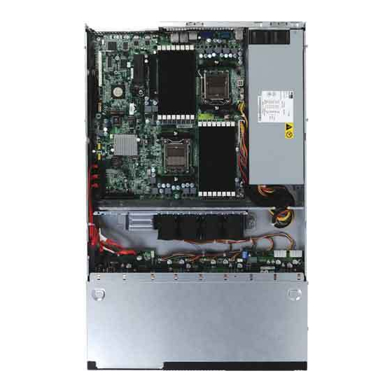
System Appearance Chapter 3 Appearance of GS-R1231-RH 3-1: Front View of GS-R1231-RH Hot-Swap SATA HDDs USB connectors Front panel switch and LEDs 3-2: Rear View of GS-R1231-RH Power cord Mouse connector Keyboard connector COM port VGA port USB connectors RJ45 LAN ports... -
Page 19: 3-3: Switch And Led Indicators Introduction
GS-R1231-RH Rack Mount Server 3-3: Switch and LED Indicators Introduction Reset Switch LAN1/2 Activities System LED ID BTN&LED NMI Switch Power Name Color Condition Description Green Power On Power Green Blink Sleep (S1) Power Off (S4) Amber Blink System Ready but degraded, CPU Failed,... -
Page 20: 3-4: Lan Led Description
LED Description 3-4: LAN LED Description Name Color Condition Description Green LAN Link / no Access Link/Activity Green BLINK LAN Access Idle 10 LAN 10Mbps connection Speed 100 LAN Green 100Mbps connection Speed Green BLINK Port identification with 10 or 100Mbps connection GbE LAN Yellow 1Gbps connection... -
Page 21: 3-5: Connector Icon Description
GS-R1231-RH Rack Mount Server 3-5: Connector Icon Description Suggest Icon Description Keyboard Mouse... -
Page 22: Chapter 4 Motherboard Jumper Setting
Motherboard Layout Chapter 4 Motherboard Jumper Setting 4-1: GA-3CESL1-RH Motherboard Jumpper Setting CLR_CMOS1... - Page 23 GS-R1231-RH Rack Mount Server 1. CLR_CMOS ( (Clear CMOS jumper) You may clear the CMOS data to its default values by this jumper. Default value doesn’t include the “Shunter” to prevent from improper use this jumper. To clear CMOS, temporarily short 1-2 pin.
-
Page 24: Chapter 5 Bios Setup
BIOS Setup Chapter 5 BIOS Setup BIOS Setup is an overview of the BIOS Setup Program. The program that allows users to modify the basic system configuration. This type of information is stored in battery-backed CMOS RAM so that it retains the Setup information when the power is turned off. -
Page 25: Getting Help
GS-R1231-RH Rack Mount Server GETTING HELP Main Menu The on-line description of the highlighted setup function is displayed at the bottom of the screen. Status Page Setup Menu / Option Page Setup Menu Press F1 to pop up a small help window that describes the appropriate keys to use and the possible selections for the highlighted item. -
Page 26: Main
BIOS Setup Main Once you enter Phoenix BIOS Setup Utility, the Main Menu (Figure 1) will appear on the screen. Use arrow keys to select among the items and press <Enter> to accept or enter the sub-menu. Figure 1: Main System Time The time is calculated based on the 24-hour military time clock. - Page 27 GS-R1231-RH Rack Mount Server Processor Information These following items display all information of current CPU Type, CPU Speed, and CPU Count. These items are display-only which is determined by POST (Power On Self Test) of the BIOS Total Memory Size...
-
Page 28: Advanced
BIOS Setup Advanced About This Section: Advanced With this section, allowing user to configure your system for basic operation. User can change the processor options, chipset configuration, PCI configuration and chipset control. Figure 2: Advanced... -
Page 29: Advanced Processor Options
GS-R1231-RH Rack Mount Server Advanced Processor Options Figure 2-1: Advanced Processor Option Advanced Processor Option This category includes the information of CPU Type, CPU Speed, CPU1/CPU2 ID, CPU1/CPU2 L2/L3 Cache, CPU Type, CPU Speed. Setup menu for AMD Virtualization (TM) Technology, Enhanced Virus Protection, Power Now Technology, Node Interleave, and ACPI SRAT Table. - Page 30 BIOS Setup only virtual machine solutions. Enabled Enable AMD Virtualization Technology Feature. Disabled Disable Feature. (Default setting) AMD Virtualization Technology Enhanced Virtus Protection Enabled Enabled AMD No-execute page protection feature. (Default setting) Disabled Disables AMD No-execute page protection feature. Power Now! Technology AMD PowerNow! Technology allows the processor to dissipate less heat under normal operating conditions, providing a cooler and quieter-running system.
- Page 31 GS-R1231-RH Rack Mount Server L2 ECC Scrub Control Sets the rate of background scrubbing for the L2 cache. Options Disabled/1.28us/2.56us/5.12us/10.2us/20.5us/41us/81.9us/163.8us/ 327.7us/655.4us/1.31ms/2.62ms/5.24ms/10.49ms/20.97ms/42ms/84ms Default setting is disabled. L3 ECC Scrub Control Sets the rate of background scrubbing for the L3 cache. Options Disabled/40ns/80ns/160ns/320ns/640ns/1.28us/2.56us/5.12us/10.2us/20.
-
Page 32: Memory Configuration
BIOS Setup Memory Configuration Figure 2-2: Memory Configuration Syetem Memory/Extended Memory /DIMM Information These category is display-only which is determined by POST (Power On Self Test) of the BIOS. Clear Disabled DIMMs Press [Enter] to clear the memory error status. Save the changes and restart system. DIMM Information These category is display-only which is determined by POST (Power On Self Test) of the BIOS. -
Page 33: Advanced Chipset Control
GS-R1231-RH Rack Mount Server Advanced Chipset Control Figure 2-3: Advanced Chipset Control Wake on Keyboard/Mouse This item allows you to set the enable/disable for powering-on the system by keyboard and mouse. Enabled Wake on Keyboard/Mouse. (Default setting) Disabled Disable this function. - Page 34 BIOS Setup Wake On RTC Alarm You can set "RTC" items to enabled and key in Data/time to power on system. Enabled Enable alarm function to POWER ON system. Disabled Disable this function. (Default setting)
-
Page 35: Pci Configuration
GS-R1231-RH Rack Mount Server PCI Configuration Figure 2-4: PCI Configuration PCI Slot 1Option ROM Enabled Enable this item to initialize device expansion ROM. (Defualt setting) Disabled Disable this function. Onboard LAN1 Control Enabled Enable onboard LAN1 device. (Defualt setting) Disabled Disable this function. - Page 36 BIOS Setup Onboard LAN2 Control Enabled Enable onboard LAN1 device. (Defualt setting) Disabled Disable this function. LAN2 Optiona ROM Scan Enabled Enableing this item to initialize device expansion ROM. (Defualt setting) Disabled Disable this function. Onboard VGA Control Enabled Enable onboard VGA device. (Defualt setting) Disabled Disable this function.
-
Page 37: I/O Device Configuration
GS-R1231-RH Rack Mount Server I/O Device Configuration Figure 2-5: I/O Device Configuration Serial Port A This allows users to configure serial prot A address by using this option. Enabled Set serial port A address to 3F8/IRQ4. Disabled No configuration. Auto Auto-detection. -
Page 38: Usb Control
BIOS Setup PS/2 Mouse Set this option ‘Enabled’ to allow BIOS support for a PS/2 - type mouse. Enabled ‘Enabled’ forces the PS/2 mouse port to be enabled regardless if a mouse is present. (Default setting) Disabled ‘Disabled’ prevents any installed PS/2 mouse from functioning, but frees up IRQ12. - Page 39 GS-R1231-RH Rack Mount Server NV RAID Configuration Enabled Enable nVIDIA RAID control. (Default setting) Disabled Disable the Serial ATA0 device. SATA0~5 Enabled Enable SATA 0~5 RAID control (Default setting) Disabled Disable SATA 0~5 RAID control.
-
Page 40: Ide Configuration
BIOS Setup IDE Configuration Figure 2-6: IDE Configuration Primary Master, Slave/SATA0~5 The category identifies the types of hard disk from drive C to F and SATA 0~SATA 5 are installed in the computer. System will automatically detect HDD type. Note that the specifications of your drive must match with the drive table. The hard disk will not work properly if you enter improper information for this category. - Page 41 GS-R1231-RH Rack Mount Server TYPE Auto: Set parameters automatically. (Default setting) CD/DVD: Use fo CD/DVD ROM drives or double click [Auto] to set all HDD parameters automatically. Clear: Removable disk drive is installed here. ATAPI Removable: Removable disk drive is installed here.
-
Page 42: Boot Configuration
BIOS Setup Boot Configuration Figure 2-7: Boot Configuration Boot -time Diagnostic Screen When this item is enabled, allows BIOS to skip certain tests while booting. Enabled Enable Boot-time Diagnostic. Disabled Disable this function. (Default setting) Multiprocessor Specification This option allows user to configure the multiprocessor(MP) specification revision level. Some operating system will require 1.1 for compatibility reasons. - Page 43 GS-R1231-RH Rack Mount Server Post Error Pause All Errors Whenever the BIOS detects a non-fatal error the system will be stopped. All, But Keyboard The system boot will not stop for a keyboard error; it will stop for all other errors. (Default setting)
-
Page 44: Security
BIOS Setup Security About This Section: Security In this section, user can set either supervisor or user passwords, or both for different level of password securities. In addition, user also can set the virus protection for boot sector. Figure 3: Security Set Supervisor Password You can install and change this options for the setup menus. -
Page 45: Set User Password
GS-R1231-RH Rack Mount Server Set User Password You can only enter but do not have the right to change the options of the setup menus. When you select this function, the following message will appear at the center of the screen to assist you in creating a password. -
Page 46: Server
BIOS Setup Server Figure 4: Server... -
Page 47: System Management
GS-R1231-RH Rack Mount Server System Management Figure 4-1: System Management Server Management This category allows user to view the server management features. Including information of BIOS Version, System Product Name, System Serial Number, BaseBoard ID, Main Board Serial Number, System ID, BMC Firmware Version, and, FRU Revision. All items in this menu cannot be modified, display only. -
Page 48: Console Redirection
BIOS Setup Console Redirection Figure 4-2: Remote Access Configuration COM Port Adress If this option is set to enabled, it will use a port on the motherboard. On-board COM A Use Serial Port A as the COM port address. On-board COM B Use Serial Port B as the COM port address. -
Page 49: Exit
GS-R1231-RH Rack Mount Server Flow Control This option provide user to enable the flow control function. None Not supported. XON/OFF Software control. CTS/RTS Hardware control. (Default setting) Continue C.R. after POST This option allows user to enable console redirection after O.S has loaded. -
Page 50: Event Log Configuration
BIOS Setup Event Log Configuration Figure 4-3: Event Log Configuration Clear all Event Logs Press [Enter] to clear all IPMI Event logs. Log POST Sys. Event Enabled Enable Log POST Sys. Event function. (Default setting) Disabled Disable this function. -
Page 51: Boot
GS-R1231-RH Rack Mount Server Boot Figure 5: Boot Boot Device Priority This field determines which type of device the system attempt to boot from after BIOS POST completed. Specifies the boot sequence from the available devices. If the first device is not a bootable device, the system will seek for next available device. -
Page 52: Exit
BIOS Setup Exit Figure 6: Exit About This Section: Exit Once you have made the changes in the BIOS setup items, you have to save your changes and exit BIOS setup program. Select “Exit” from the menu bar, to display the following sub-menu. - Page 53 GS-R1231-RH Rack Mount Server Exit Saving Changes This option allows user to exit system setup with saving the changes. Press <Enter> on this item to ask for the following confirmation message: Pressing ‘Y’ to store all the present setting values tha user made in this time into CMOS.
-
Page 54: Exit Discarding Changes
BIOS Setup Exit Discarding Changes This option allows user to exit system setup without changing any previous settings values in CMOS. The previous selection remain in effect. This will exit the Setup Utility and restart your compuetr when selecting this option. - Page 55 GS-R1231-RH Rack Mount Server Load Setup Default This option allows user to load default values for all setup items. When you press <Enter> on this item, you will get a confirmation dialog box with a message as below:...
-
Page 56: Discard Changes
BIOS Setup Discard Changes This option allows user to exit system setup without changing any previous settings values in CMOS. The previous selection remain in effect. This will exit the Setup Utility and restart your compuetr when selecting this option. -
Page 57: Save Changes
GS-R1231-RH Rack Mount Server Save Changes This option allows user to save setup dat ato CMOS. When you press <Enter> on this item, you will get a confirmation dialog box with a message as below: Press [Yes] to save setup daya to CMOS.