Planet VC-201A User Manual
Ethernet over vdsl2 converter
Hide thumbs
Also See for VC-201A:
- Specifications (4 pages) ,
- User manual (32 pages) ,
- User manual (36 pages)
Table of Contents
Advertisement
Quick Links
Download this manual
See also:
User Manual
Advertisement
Table of Contents

Related Manuals for Planet VC-201A


Summary of Contents for Planet VC-201A
- Page 1 Ethernet over VDSL2 Converter VC-201A / VC-204 User’s Manual...
-
Page 2: Fcc Warning
Copyright © PLANET Technology Corp. 2009 Contents subject to revision without prior notice. PLANET is a registered trademark of PLANET Technology Corp. The information in this manual is subject to change without notice. All other trademarks belong to their respective owners. - Page 3 Do not dispose of WEEE as unsorted municipal waste and have to collect such WEEE separately. Revision Ethernet Over VDSL2 Converter User’s Manual For Models: VC-201A / VC-204 Rev 1.0 (January 2009) Part No.: 2350-AC0110-000...
-
Page 4: Table Of Contents
3. Installing and Using VDSL Converter ....... 19 3.1 Install the Ethernet Over VDSL2 Converter ....19 3.1.1 VC-201A / VC-204 LAN to LAN connection ..20 3.1.2 VC-201A / VC-204 Connect to Multi-Port Master . 20 3.2 Connecting VC-201A / VC-204 ........21 3.2.1 Connecting Standalone PC ........ -
Page 5: Introduction
Ethernet over VDSL port (symmetry means upstream and downstream rate are the same or similar) – the VDSL port can be RJ-11 connectors. The VC-201A / VC-204 can be set to CO mode or CPE mode via a DIP switch. When the... - Page 6 Slave device (CPE) must connect to Master device (CO) through the telephone wire. Slave cannot connect to Slave and Master cannot connect to Master. To define the VC-201A / VC-204 to CO or Note CPE, please refer to section 2.2.1 for more detail.
- Page 7 Telco CO, wire closet Ethernet over VDSL and Telephone Network Telephone wire VDSL2 Up to 1.6km Main office/PBX, Telco CO, wire closet VC-201A/CO VC-201A/CPE LAN1 LAN2 Ethernet over VDSL and Telephone Network Telephone wire VDSL2 Up to 1.6km Main office/PBX,...
- Page 8 Multi-LAN Connection Existing Telephone Network Telephone wire Main office/PBX, Telco CO, wire closet Ethernet over VDSL and Telephone Network Telephone wire VDSL2 VDSL2 Switch VC-201A/CPE (Multi-port CO) LAN1 Main office/PBX, Telco CO, UP to 1.6km wire closet VDSL2 VC-201A/CPE LAN2...
-
Page 9: Key Features
1.3 Key Features The Ethernet Over VDSL2 Converter provides the following key features: Cost-effective VDSL2 CO/CPE bridge solution One box design, CO/CPE selectable via DIP Switch Defines asymmetric (Plan 998) and symmetric (Plan 997) band plans for the transmission of upstream and downstream signals Complies with IEEE 802.3, IEEE 802.3u and IEEE 802.3x standards... -
Page 10: Specifications
1.4 Specifications Product VC-201A VC-204 Hardware Specification 1 RJ-45, Auto-negotiation 4 RJ-45, Auto-negotiation 10/100Base-TX and Auto-MDI/MDI-X and Auto-MDI/MDI-X Ports VDSL 1 RJ-11, female Phone Jack PHONE 1 RJ-11, Built-in splitters for POTS connection DIP Switch 4 position DIP switch • CO / CPE mode select •... - Page 11 Asymmetric Mode 200m -> 100/55Mbps 400m -> 90/50Mbps 600m -> 70/40Mbps 800m -> 60/25Mbps 1000m -> 45/15Mbps 1200m -> 35/10Mbps Performance* 1400m -> 30/6Mbps 1600m -> 25/4Mbps (Down Stream / Symmetric Mode Up Stream) 200m -> 100/100Mbps 400m -> 90/95Mbps 600m ->...
-
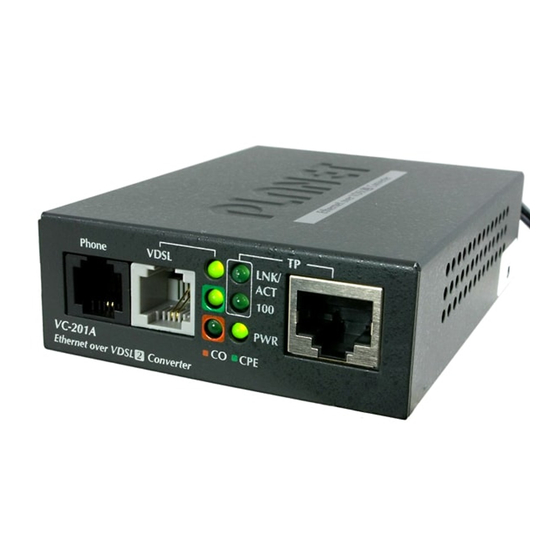
Page 12: Hardware Description
The VC-201A / VC-204 provides 2 RJ-11 ports for voice connection (like telephone) and for network line connection. The VC-201A provide 1 RJ-45 ports and VC-204 provide 4 RJ-45 ports for two different running speed –10Mbps, 100Mbps, in the same bridge and automatically distinguish the speed of incoming connection. -
Page 13: Led Indicators For Vc-201A
VC-204 Front Panel Figure 2-2: VC-204 front panel 2.1.1 LED indicators for VC-201A The rich diagnostic LEDs on the front panel can provide the operating status of individual port and whole system. n System Color Function Power ON Green... -
Page 14: Led Indicators For Vc-204
n 10/100Base-TX Port Color Function Indicate that the port is link up. Indicate that the Converter is actively LNK/ Green Blink sending or receiving data over that port. Indicate that the port is link down. Indicate that the port is operating at 100Mbps. - Page 15 n VDSL Color Function Indicate that the VDSL link is established. Fast Indicate that the VDSL link is at Blink training status(about 10 seconds). Green Slow Indicate that the VDSL link is at idle Blink status. Indicate that the port is link down. Indicate that the VDSL link is established.
-
Page 16: The Rear Panel
The rear panel of the Ethernet Over VDSL2 Converter is shown as below. n VC-201A Rear Panel 1 2 3 4 Figure 2-3: VC-201A rear panel n VC-204 Rear Panel 1 2 3 4 Figure 2-4: VC-204 rear panel 2.2.1 MODE DIP Switch The Ethernet Over VDSL2 Converter provides 4 selective transmission modes. - Page 17 DIP-1 DIP-2 DIP-3 DIP-4 Mode Channel Band Plan Interleave Symm ON (default) Fast Asymm CO / CPE u CO (Central Office) – the Master device mode, usually the CO device will be located at the data center of ISP or enterprise to link to the backbone.
- Page 18 2.2.2 DC power jack VC-201A / VC-204 require 5V DC power input. It will conform to the bundled AC adapter. Should you have the problem to make the power connection, please contact your local sales representative.
-
Page 19: Installing And Using Vdsl Converter
The device is used for Point-to-Point connection only (Master device to Slave device) and allows data and voice work on the same telephone lines. VC-201A / VC-204 two RJ-11 connectors for VDSL port. One for voice device connection (like telephone) and the other one for network link connection. -
Page 20: Vc-201A / Vc-204 Lan To Lan Connection
3.1.1 VC-201A / VC-204 LAN to LAN connection Two sets of the Ethernet Over VDSL2 Converters could be used to link two local Area networks that are located in different place. Through the normal telephone line, it could setup a... -
Page 21: Connecting Vc-201A / Vc-204
Refer to the following procedures to setup the VC-201A to a standalone PC. 1. Set the VC-201A to be CO mode or CPE mode from the DIP switch at the rear panel. 2. Power on the VC-201A by connecting its power source. -
Page 22: Connecting Multiple Pcs To An Ethernet Lan
Refer to the following procedures to setup the VC-201A / VC- 204 to an Ethernet LAN. 1. Set the VC-201A / VC-204 to be CO mode or CPE mode from the DIP switch at the rear panel. 2. Power on the VC-201A / VC-204 by connecting its power source. - Page 23 Figure 3-4: Connecting Multiple PCs to an Ethernet LAN Please refer to your Ethernet device User’s Manual for the device’s set up information. Note...
-
Page 24: Chassis Installation And Rack Mounting
3.3 Chassis Installation and Rack Mounting (VC-201A) To install the Ethernet over VDSL2 Converter in a 10-inch or 19-inch Converter Chassis with standard rack, follow the instructions described below. Step 1: Place your chassis on a hard flat surface, with the front panel positioned towards your front side. -
Page 25: Power Information
4. POWER INFORMATION The power jack of VC-201A / VC-204 is with 2.5mm in the central post and required +5VDC power input. It will conform to the bundled AC-DC adapter and Planet’s Media Chassis. Should you have the problem to make the power connection, please contact your local sales representative. -
Page 26: Troubleshooting
/ VC-204 is not more than 2.0km. Please also try to adjust the DIP switch or VC-201A / VC-204 to other SNR mode. 2. Please note you must use one VC-201A / VC-204 with CO mode and the other VC-201A / VC-204 with CPE mode, connect to each other to make it work. -
Page 27: Faq
VC-201A / VC-204. Q4: What is the best date rate for VC-201A / VC-204? A4: We provide the data rate of the VC-201A / VC-204 is up to 100Mbps/55Mbps (downstream / upstream) in 200 meters. Q5: Can VC-201 compatible with VC-201A / VC-204? A5: Currently NO. - Page 28 Q6: What is SNR and what’s the effect? A6: In analog and digital communications, Signal-to-Noise Ratio, often written SNR, is a measure of signal strength relative to background noise. The ratio is usually measured in decibels (dB). In digital communications, the SNR will probably cause a reduction in data speed because of frequent errors that require the source (transmitting) computer or terminal to resend some packets of data.