Table of Contents
Advertisement
Quick Links
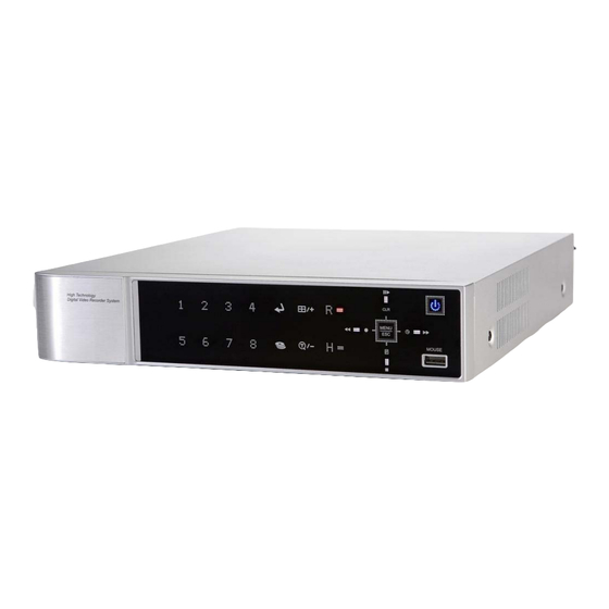
DIGITAL VIDEO RECORDER
• Thank you for purchasing this Digital Video Recorder.
• Before using the Digital Video Recorder, please ensure you read, and understand,
this User Manual.
• Please store the User Manual in a safe loction for future reference.
• Refer to the appropriate instruction manuals before connecting or installing any
third party equipment.
User Manual
Product Code: BDVRH
4, 8, 16-Channel Models
0
Advertisement
Table of Contents

Related Manuals for Genie BDVRH


Summary of Contents for Genie BDVRH
-
Page 1: Digital Video Recorder
DIGITAL VIDEO RECORDER User Manual Product Code: BDVRH 4, 8, 16-Channel Models • Thank you for purchasing this Digital Video Recorder. • Before using the Digital Video Recorder, please ensure you read, and understand, this User Manual. • Please store the User Manual in a safe loction for future reference. -
Page 2: Safety Precautions
Safety Precautions CAUTION: TO REDUCE THE RISK OF ELECTRIC SHOCK, DO NOT REMOVE THE COVER . NO USER SERVICEABLE PARTS INSIDE. REFER SERVICING TO QUALIFIED SERVICE PERSONNEL. A lightning flash with an arrowhead symbol, within an equilateral triangle, is intended to alert the user to the presence of uninsulated “dangerous voltage”... -
Page 3: Table Of Contents
Disclaimer .................... 5 Warning ....................5 Caution ....................7 Preventing Malfunctions ..............7 Regulatory ................... 7 Package Contents ................8 I.CONTROLS ..................9 1. Front Panel ....................... 9 2. Rear Panel Connectors ..................12 3. Remote Controller ....................13 4. Mouse Control ....................... 14 5. - Page 4 3. RECORD ........................32 3.1. Record General ......................32 3.2. Resolution & Recording Speed Setting ............33 3.3. Continuous /Normal Recording ................ 34 3.4. Event Recording ...................... 35 3.5. Continuous + Event (Motion/Alarm) Recording ........37 4. SCHEDULE ......................38 4.1.
- Page 5 2.2. Preview Search (Single Channel Playback) ........... 67 2.3. Event Record Search ..................68 2.4. Event Source Search ..................69 2.5 Motion Area Search (Single Channel Playback) ........... 71 3. Go to Search ......................72 4.Log List Search ...................... 73 IX.BACKUP ..................
-
Page 6: Disclaimer
Disclaimer The information in this manual is believed to be accurate and reliable as of the date of publication. The information contained herein is subject to change without notice. Revisions or new editions to this publication may be issued to incorporate such changes. - Page 7 Do not use substances containing alcohol, benzene, thinners or other flammable substances to clean or maintain the equipment. The use of these substances may lead to fire. Use a dry cloth on a regular periodic basis and wipe away the dust and dirt that collects on the device.
-
Page 8: Caution
Caution Do not operate the appliance beyond its specified temperature, humidity or power source ratings. Do not use the appliance in an extreme environment where there is high temperature or high humidity. Use the device at temperatures within 0°C - +40°C (32°F - 104°F) and humidity below 90%. The normal operating power source for this device is DC12V 50/60Hz. -
Page 9: Package Contents
INTERFERENCE CAUSED BY UNAUTHORISED MODIFICATIONS TO THIS EQUIPMENT. SUCH MODIFICATIONS COULD VOID THE USER'S AUTHORITY TO OPERATE THE EQUIPMENT. CAUTION - Risk of Explosion if Battery is replaced by an incorrect type. Dispose of used Batteries according to the Instructions. - The socket-outlet should be installed near the equipment and accessible be easily... -
Page 10: I.controls
I.CONTROLS 1. Front Panel 4-Channel 8-Channel 16-Channel 1. Mode Indicator: 3x LED’s display the status of the Digital Video Recorder. Power (Blue), Recording (Red) and HDD (Green) Playback/Record Control: Functions for Live and Playback modes. 1) Direction buttons: In Menu setup mode, used to move the cursor. - Page 11 [LOG / Playback Stop] ① Log: Press this button to access the log list. ② Stop: This button stops playback. [R Step or FR / REC ] ① Reverse Step: This button is used to move reverse field by field during STILL mode.
- Page 12 appropriate dates in schedule option mode. [-, +] To Decrease a setting, to Increase a setting. 7. Remote Control Signal Receiver Do not block the receiver port on the unit. Doing so may cause problems when using the remote controller. 8.
-
Page 13: Rear Panel Connectors
2. Rear Panel Connectors <4ch> <8ch> <16ch> 1) CAMERA IN (4-Ch/8-Ch): BNC Input (Camera 1~4, 1~8). CAMERA IN/AUDIO IN 2~4 (1-Ch): Video / Audio Input with the connector enclosed. 16-Channel Video In & 2-Ch~4-Ch Audio In. 2) OUT: VIDEO - BNC standard composite video out, SPOT - Spot Out. 3) AUDIO: IN –... -
Page 14: Remote Controller
3. Remote Controller... -
Page 15: Mouse Control
4. Mouse Control This DVR can be controlled by mouse. 1) Left-Button -Double Click on any channel to enlarge to full screen while in a split-screen display mode. Double click again to return. Select a menu option when navigating through the various menu options. 2) Right Button- Right click anywhere on the screen to open the Main Menu. -
Page 16: Installation & Connections
II. INSTALLATION & CONNECTIONS 1. Camera, Monitor, Audio, Alarm Sensor and Power Cord... -
Page 17: Pc System Requirements For Network Connection
2. PC System Requirements for Network Connection. Minimum Recommended Windows XP SP3 or higher Windows 7 Core2 Duo PCI-E 256M PCI-E 512M DIRECTX DX9.0 SUPPORT DX9.0 SUPPORT NETWORK 100Mb ETHERNET LAN 100Mb ETHERNET LAN 100Gb 500Gb Disclaimer The connection and remote viewing of the DVR may not be successful on all PC’s due to the variety of internet connection settings. -
Page 18: Iii.quick Start Page
III.QUICK START PAGE ADMIN and the default password is “000000” The Default User ID “admin” and password to run the EMS software is “0”. -
Page 19: Main Menu
Main Menu Each Icon in the main menu works as a shortcut for setting and operation of the DVR. Use the remote control, front buttons or a mouse to select the menu you want. Time & Date Setting When the DVR is powered on for the first time the time and date are set by default to January 1, 2009 Thursday 01:00:00. -
Page 20: Iv.live Viewing
IV.LIVE VIEWING 1. Display Overview 1.1. Recording Mode The channel number background colours vary according to their recording status. 1) Red - Event (Motion/Alarm) Recording 2) Yellow - Continuous Recording 3) Black - Not Recording (1) (2) (3) 1.2. Event Indicator (1) Indicates an Alarm In terminal is triggered by an alarm sensor. - Page 21 1.3 Status Bar (1) Indicates Recording Status. Red shows Recording is being processed. Click this ICON to toggle Record Start and Stop. (2) Indicates Playback Status. Green is Playback. Click this ICON to toggle Playback Start and Stop. (3) Clear Menu and LOG (Mouse click) (4) Displayed when schedule recording is On.
-
Page 22: Multi-Screen Display And Sequencing
2. Multi-Screen Display and Sequencing 2.1. Screen Display. Select any camera for Full Screen display by pressing the Number button of the related camera. 2.2. Multi-Screen Display and Switch Sequencing Display. 1) Press the DISPLAY button to activate the multi-screen display. It changes the order from the choices shown in SPLIT MODE. -
Page 23: Quick Button For Multi-Screen Display
3. Quick Button for Multi-Screen Display. 3.1. Quick Multi-Split Mode Change - Press the F1 button on the remote controller + <Number> For example, press F1 button then number 8. The eight channel view mode will be displayed. Note: 6,4,8,10,13 split modes must be ticked on the Split Mode options to use this function. -
Page 24: Zooming
4. Zooming During live view mode it’s possible to zoom into a section of the screen to get a close-up view. 1. To activate the digital zoom, select the full screen display of the camera you wish to zoom. 2. Then press the ZOOM button on the IR Remote controller. The Zoom area box pops up, as shown below: 3. -
Page 25: Navigating The Menu
2) When the DVR is powered on, it starts to scan the DVR status. 3) Live Viewing screen appears after initialisation (about 50sec.) It can be delayed if you have a defective HDD. It will try to fix a logical problem but will show you a warning message for a physical problem. -
Page 26: Setup
Note: Changes are saved automatically saved when you move between TAB menus. 6. The menus are displayed with options in the left-hand column and settings in the right hand column. A cursor (highlighted menu) can be moved using the Direction buttons 7. -
Page 27: Switching Setup (Monitor Configure)
GREY WHITE BLUE BLACK DARK GREY The main video output can be displayed on a VGA and analogue monitor. Video can be displayed on both monitors simultaneously. OSD ALIGNMENT Select On Screen Display co-ordinates on Monitor. - Under Scan: Displays properly on CCTV Monitor. - Over Scan: Displays properly on VGA Monitor. -
Page 28: Event
c. Event: To display a particular camera in full screen or in multi-mode when an event is triggered. 4) Split Mode: Select desired sequence mode for switching. Note: This function is limited to SPOT Monitor use with this model. 5) Use Channel: Select the cameras to be included or excluded from the automatic switching. -
Page 29: Camera
When the selected event is triggered - such as alarm, motion or video loss - it is displayed on the monitor that is configured for the event. 2. Camera Configure the properties of cameras – e.g. Motion Detection, Video Adjustment (Brightness, Contrast, Colour, Saturation), Privacy Mask and PTZ sections. -
Page 30: Video Adjustment
1. Motion Level: The sensitivity settings are 1~20 – where 1 is the lowest level. By default, the level is set to 10. 2. Motion Grid: The area properties are highlighted and motion detection can now be observed in the view window. By default, it’s OFF. : Select All. -
Page 31: Privacy Mask
The colour for each camera can be adjusted by pressing COLOUR the [-,+] buttons. The saturation for each camera can be adjusted by SATURATION pressing the [-,+] buttons. 2.3. Privacy Mask Privacy Mask allows you to obscure certain areas in the surveillance video for privacy protection and conform to related privacy laws, policies and regulations. -
Page 32: Ptz Setup
2.4. PTZ Setup PTZ devices are connected to the RS-422 ports located on the back of the unit. Multiple PTZ cameras are connected by daisy-chaining the camera connection. This DVR allows you to address and control multiple PTZ cameras individually. To Configure PTZ Setup: 1) Select a Camera number button to configure the camera. -
Page 33: Camera Title
2.5. Camera Title Allows you to create a unique name for each camera. The camera title has the following guidelines: - Characters: A to Z, 0 to 9. Special characters are supported via network. - Length: Up to 12 alphanumerics, including spaces. Create a camera title using the virtual keyboard, or by pressing the appropriate numeric buttons on the IR Remote (see below) or front panel. -
Page 34: Resolution & Recording Speed Setting
the need to press the REC button - when set to ON. 3) Disk Overwrite: Select the record policy of the hard disk drive. - ON: By default, the HDD overwrites from the beginning when full. - OFF: Stops recording when the HDD is full. 5) Auto Delete: Allows you to configure when the DVR automatically deletes all data from HDD. -
Page 35: Continuous /Normal Recording
Note: Total fps is displayed as SUM/MAX. MAX for NTSC is 480 and for PAL 400. If the sum of fps is over the MAX fps a warning message pops up. Then the last channel is automatically disabled. 3.3. Continuous /Normal Recording The DVR comes with certain preset settings from the factory. -
Page 36: Event Recording
3.4. Event Recording Users can set different event recording parameters on a camera by camera basis. Set the continuous recording to OFF and configure the Event recording speed and quality for each camera. Select Alarm, Motion, Video Loss for EVENT recording on the DAY EVENT tab. 1) Alarm Recording One Alarm input can be configured to one channel. - Page 37 a. Press the [-, +] buttons to change values or select options. By mouse, use the scroll wheel. b. [※] Indicates multiple alarm sources are selected. Please refer to [CAMERA] menu for Motion setup. Note: There may be cases when the recorder’s built-in motion detection function does not operate properly due to the condition of the input video signal or other factors.
-
Page 38: Continuous + Event (Motion/Alarm) Recording
b. Event Edit - Press ENTER to edit multiple events. The menus are displayed with options in the left-hand column and settings in the right hand column. A cursor (highlighted menu) can be moved using the direction buttons on the IR remote or front panel. - Change options using the DEC/INC buttons on the IR remote or by clicking with the mouse. -
Page 39: Schedule
4. SCHEDULE When the schedule is on, users can define their own day time, night time, as well as specifiying date settings. A schedule can be used to record selected cameras at different times, change record rates and select whether alarms or events are enabled. -
Page 40: Holiday Setup
3) A detailed menu pops up for selected day, as shown below. a. Use [-, +] buttons to change the values. Mode: [Night] [Day] [No Rec] BEGIN: The start time of recording. END: The end time of recording. The end time must not be before the start time or the same as the start time. -
Page 41: Disk
1) A cursor (highlighted menu) can be moved using the direction buttons Select each day to configure, press ENTER or click the mouse. Use the [-, +] buttons to change values. Mode: [OFF] [Day] [Night] [No Rec] [Sun~Sat] [Custom] Date: The start date of the Holiday. Days: The duration of the holiday [1 to 15 days]. - Page 42 respective capacities. 3) Status: a. CD/DVD: CD or DVD is installed for back up usage. b. Unknown: New installed Disk. c. Empty: Formatted but not used in current DVR. d. Recording Data: HDD stored Recording data but not used in current DVR.
-
Page 43: Recording Disk
Device ODD (Media) CD/DVD±R CD/DVD SATA ±RW Media can be formatted Device can be formatted on a PC using FAT32 NTFS File system. Media must be formatted on DVR before backing up or exporting data to the device. Note1: USB flash memory works without format. Note2: if a FAT32 /NTFS formatted external USB device is installed, <Assign to Stream>... -
Page 44: Status
synchronisation the Master HDD can be removed as well. 3. Status 1) Stable: The HDD is in a stable condition. 2) Sync: Copy Master HDD to the Slave HDD. 3) Re-sync: To force all pending buffered disk writes to the NEW installed disk. -
Page 45: Network
6. NETWORK The static service consists of an IP address which remains constant for the duration of the contract of the internet service. Whereas the dynamic service consists of an IP address that changes every time a new connection is made through the provided modem, or recurrently in a given period of time. -
Page 46: General
6.2. General 1. Access Port: Select “0001 ~ 9999” Enter the port number the client will use to communicate with the DVR over the internet. The default port is 7000. It is recommended to use a port number higher than 1,000. 2. -
Page 47: Email
6.3. Email This DVR allows you to specify the events that generate notifications. Sends email notification if an event occurs such as alarm or motion is detected etc. The mail server can use either the DVR mail server or your existing email settings. -
Page 48: Smtp
2) Log: This DVR will mail the Log list at selected intervals. 5. Attach Picture: While in record mode, a picture can be attached to the email. Email Address: 5 mail addresses can be configured for mail notification. 6.4. SMTP This menu is activated when you check SMPT on EMAIL. -
Page 49: Ddns (Dynamic Dns)
6.5. DDNS (Dynamic DNS) This DVR offers free dynamic DNS update. It keeps track of your changing IP address. The menus are displayed with options in the left-hand column and settings in the right hand column. A cursor (highlighted menu) can be moved using the Direction buttons 1. -
Page 50: Router & Port Forwarding
2) DYNDNS: To use your own domain name service or “dyndns.com” 2. The following settings are only needed if you are NOT using the default. 1) Domain Name: Enter the name you set for the DDNS web configuration. 2) User ID: Enter your user ID. 3) Password: Enter your password. - Page 51 Here is an example of DVR connection. PC Connect PC Connect Position Position Network Router DVR IP Setting ① LAN ② WAN STATIC ○ X ★ ★ Check the DVR IP info DHCP ○ ▲ X ☆ ★ and set into Router. Static IP STATIC ○...
-
Page 52: Device
x : Not able to connect. : There’s some limitation - depends on Router or Network connection. ★ : Need to use Port Forwarding. 3) Description of Colours Used Yellow - Recommended Grey - Not available White – Depends on Router or Network condition. 2. -
Page 53: Alarm
Automatically detects and sets the correct video resolution on the monitor by default. [800x600 1024x768 1280x720 1280x1024 1600x1200 1680x1050 1920x1080I 1920x1080P] HDMI Auto Automatically detects and sets the HDMI resolution for the monitor connected to the DVR. “no video” may be displayed if a VGA monitor is not able to support high resolution. - Page 54 displayed with options in the left-hand column and settings in the right hand column. A cursor (highlighted menu) can be moved using the direction buttons 2. Input: Change the input type. Use the [-, +] buttons to change values. 3. Output: You can configure how the relay outputs are controlled: automatic or manual.
-
Page 55: Ptz Event
Network Link Disconnected Admin Login Power Recovery Disk Full Invalid Password in Sequence Auxiliary Event (Reserved ) 4) Control: To manually stop the Relay Output and Buzzer. 4. Buzzer 1) Use ON: The buzzer sounds if an alarm is triggered. The buzzer sounds for the duration of the RECORD TIME. -
Page 56: System
1. Channel: Select desired PTZ camera. 2. Active: Configure PTZ action [NONE GOTO TOUR] and Preset Number or Tour group when an event is detected. 3. Inactive: Select Camera position after event duration expires. 4. Event Edit: Press ENTER to edit multiple events. The menus are displayed with options in the left-hand column and settings in the right hand column. -
Page 57: Time
- To select the DVR to be controlled with the remote controller, press and hold the DVR ID button. While holding the DVR ID button, press the appropriate DVR ID number. For example, enter 05 for DVR ID 05, enter 43 for DVR ID 43, etc. - Page 58 1. Use Left/Right buttons [ ] to select the “Time” tab menu. The menus are displayed with options in the left-hand column and settings in the right hand column. A cursor (highlighted menu) can be moved using the direction buttons .
-
Page 59: Account
6) Date & Time : Set current time and date. 2. To save changes and exit the menu, press the MENU button. Exit the menu without making changes, press the CANCEL button. 8.3. Account 1. Use Left/Right buttons [ ] to select the “Account” tab menu. The menus are displayed with options in the left-hand column and settings in the right hand column. -
Page 60: Update
3) Network: The DVR comes preconfigured with a System password to access the Network access and Deny for Users. It is possible to create different passwords for Network access by choosing Custom Password. a. Password Length: up to 14characters. b. Characters: A to Z, numerals 0 to 9. 4) Channel Allow each user to view different live monitoring. -
Page 61: Info
3. Using the direction buttons move to the START button. Press the [+] buttons to find the upgrade file(s). If the DVR finds a valid update file, the update menu is activated. 4. Press the [-, +] buttons to find upgrade files. Version information is displayed. -
Page 62: Pan/Tilt Zoom Control
status DISK: Contains all DISK information including that for internal & external HDD’s and USB memory. NETWORK: Displays IP Address, User ID and service of network user. VII. PAN/TILT ZOOM CONTROL PTZ control is available for supported third-party dome cameras. The PTZ option must be configured for each camera channel. - Page 63 Note: Please Refer to the Help Menu for specific control. INDICATOR ACTIONS Press this button to display “HELP” Menu. Press the ENTER Button again, or the CANCEL button to cancel the Help Menu. ENTER CANCEL Press this button to cancel “PAN/TILT” Operation. PTZ camera control interface will be extended to use all functions.
- Page 64 3) Place the mouse cursor inside the rectangle boundary, press and hold the left mouse button and move the mouse cursor in the direction you want the camera to move. Note: Mouse cursor cannot move out of the rectangle while holding down the left mouse button.
-
Page 65: Preset & Tour
2. Preset & Tour Button Function Set preset position; SPOT OUT on remote controller. Move the PTZ into desired location. Press the Preset button. Custom 1 illuminates. Set the number for the Preset location. Press Enter to Save and Exit. Go to preset position;... -
Page 66: Custom Functions
1) Communication Settings: Configure the appropriate protocol, then enter the corresponding baud rate and PTZ ID (address). Refer to the PTZ manufacturer’s instruction manual for proper jumper settings to match the protocols to the DVR. 2) Tour: There are 4 programmable Tours. Use the [-, +] buttons to change the values [Group 1 Group 2 Group 3... -
Page 67: Auto Pan / Auto Tilt / Power
4.Auto Pan / Auto Tilt / Power Button Function Auto Pan; STOP on remote controller Auto Tilt; REW on remote controller Power On / Off; FF on remote controller 6 . PTZ Camera Model – PAN/TILT/ZOOM Camera List Esc/ Model Name Speed Preset Go to... -
Page 68: Time Search
During playback the footage can be played back in reverse, paused, speed searched (up to 16 times the normal speed) or moved picture by picture. 2. Time Search 2.1. Multi-Channel Playback 1. Press the Time Search button to access the time search table. Days are displayed. -
Page 69: Event Record Search
Choose the desired channel to review by pressing a numeric button. Use the [+] button to navigate to the desired Day Hour Minute (5mins) Minute (30sec). Use the [-] button to go back Minute (30sec) Minute (5mins) Hour Day. With a mouse, the scroll wheel is used instead of the [+/-] buttons. While reviewing snapshots, use the numeric buttons to review other channels. -
Page 70: Event Source Search
1. Press the “Event Select “ button to change the Search mode. 2. Press OK to set up. Press the [+/-] buttons to select “Event Record”. 3. Press [+/-] buttons select “SEARCH MODE” (Event Source/Motion Area). Note: Event Record is set by default and makes Time Search Chart display Event Recording in Red. - Page 71 Select the event source (Alarm,Motion,VLoss) you want to search for. 1) ALARM: Select Alarm Input 1~4. 2) MOTION: Select the Channel 1~16. 3) VLOSS (Video Loss): Select the Channel 1~16. 4) SYSTEM: Inactivated 2. Users can can have multiple selections by pressing If you select MOTION 1, and press the MENU button on the remote controller, Time Search Chart displays the recorded data (in red) at the time motion was triggered on channel #1.
-
Page 72: Motion Area Search (Single Channel Playback)
If you select ALARM 1 and press the MENU button on the remote controller, Time Search Chart displays the recorded data (in red) at the time when Alarm 1 Input was triggered. Other recording data is in yellow. So users can easily search the recorded data and playback to see what happened when Alarm 1 was triggered. -
Page 73: Go To Search
2. Press the [+/- ] buttons to select the channel you want to search. 3. Select the motion area you want to search. : Select all grids. : Deselect all grids. : Select grids one by one by one by pressing the [+/- ] buttons. 4. -
Page 74: Log List Search
4.Log List Search The logs can be used to search and review recorded data directly to a point in time. Alarm, Motion, Video Loss and System related logs can be searched and played back directly from the time of the incident. To start Event Search, press Log button on the IR Remote. -
Page 75: Ix.backup
IX.BACKUP 1. Manual Back Up External USB HDD/ Memory Stick 1. Insert a USB HDD or Memory Stick into the Front Panel USB Port. 2. Press the BACKUP button on the IR Remote and the backup menu appears. 3. Use the [-, +] buttons to select device. 4.