Table of Contents
Advertisement
www.proform.com
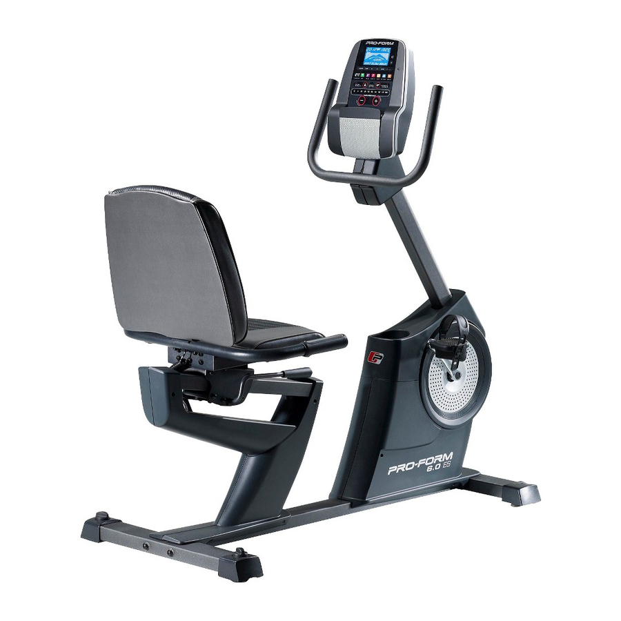
Model No. PFEX53912.0
Serial No.
Write the serial number in the space
above for reference.
Serial Number
QUESTIONS?
If you have questions, or if parts
are damaged or missing, DO NOT
CONTACT THE STORE; please
contact Customer Care.
IMPORTANT: Please register this
product (see the limited warranty
on the back cover of this manual)
before contacting Customer Care.
CALL TOLL-FREE:
1-888-533-1333
Mon.––Fri. 6 a.m.––6 p.m. MT
Sat. 8 a.m.––4 p.m. MT
ON THE WEB:
www.proformservice.com
CAUTION
Read all precautions and instruc-
tions in this manual before using
this equipment. Keep this manual
for future reference.
Decal
USER’'S MANUAL
Advertisement
Table of Contents

Related Manuals for Pro-Form 6.0 Es Bike


Summary of Contents for Pro-Form 6.0 Es Bike
- Page 1 Model No. PFEX53912.0 Serial No. Write the serial number in the space USER’’S MANUAL above for reference. Serial Number Decal QUESTIONS? If you have questions, or if parts are damaged or missing, DO NOT CONTACT THE STORE; please contact Customer Care.
-
Page 2: Table Of Contents
If a decal is missing or illegible, see the front cover of this manual and request a free replacement decal. Apply the decal in the location shown. Note: The decal(s) may not be shown at actual size. PROFORM is a registered trademark of ICON IP, Inc. -
Page 3: Important Precautions
IMPORTANT PRECAUTIONS WARNING: To reduce the risk of serious injury, read all important precautions and instructions in this manual and all warnings on your exercise bike before using your exercise bike. ICON assumes no responsibility for personal injury or property damage sustained by or through the use of this product. -
Page 4: Before You Begin
BEFORE YOU BEGIN Thank you for selecting the revolutionary PROFORM ® reading this manual, please see the front cover of this 6.0 ES exercise bike. Cycling is an effective exercise manual. To help us assist you, note the product model for increasing cardiovascular ... -
Page 5: Part Identification Chart
PART IDENTIFICATION CHART Use the drawings below to identify the small parts needed for assembly. The number in parentheses below each drawing is the key number of the part, from the PART LIST near the end of this manual. The number following the key number is the quantity needed for assembly. -
Page 6: Assembly
•• To watch an assembly •• To identify small parts, see page 5. video, go to http://productvideo.co/ •• In addition to the included tool(s), assembly assembly/proform or requires the following tools: use your mobile phone one Phillips screwdriver or smartphone to read... - Page 7 3. Slide the Shield Cover (5) upward onto the Upright (4). Avoid pinching Have a second person hold the Shield Cover (5) the wires around the Upright (4) until you complete step 4. Tip: Avoid pinching the wires inside the Frame (1).
- Page 8 5. Tip: Avoid pinching the wires. Attach the Handlebar (6) to the Upright (4) with four M6 x 20mm Screws (88) and four M6 Split Avoid pinching Washers (50). the wires 6. Insert the Main Wire (76) and the Frame Pulse Wire (75) upward through the indicated hole in the Upright (4).
- Page 9 8. Identify the Right and Left Handlebar Covers (8, 9). Attach the Right and Left Handlebar Covers (8, 9) around the Handlebar (6) and the Upright (4) with four M4 x 22mm Screws (90). 9. Attach the Seat (15) to the Seat Carriage (11) with four M6 x 50mm Screws (65) and four M6 Washers (66) (only two of each are shown).
- Page 10 10. Attach the Backrest (13) to the Seat Carriage (11) with five M8 x 16mm Screws (60) and five M8 Split Washers (61). Tip: It may be helpful to adjust the seat dur- ing this step. See HOW TO ADJUST THE SEAT on page 13.
- Page 11 12. Plug the Pulse Bar Pulse Wire (72) into the Frame Pulse Receptacle (75) located in the Left Seat Shield (24). 13. Identify the Right Pedal (16). Using an adjustable wrench, firmly tighten the Right Pedal (16) clockwise into the Right Crank Arm (17).
- Page 12 14. Plug the Power Adapter (49) into the receptacle on the frame of the exercise bike. To plug the Power Adapter into an outlet, see HOW TO PLUG IN THE POWER ADAPTER on page 13. 15. Make sure that all parts are properly tightened before you use the exercise bike. Note: Extra parts may be included.
-
Page 13: How To Use The Exercise Bike
HOW TO USE THE EXERCISE BIKE HOW TO PLUG IN THE POWER ADAPTER HOW TO ADJUST THE PEDAL STRAPS IMPORTANT: If the exercise bike has been exposed To adjust the to cold temperatures, allow it to warm to room pedal straps, temperature before plugging in the power adapter. -
Page 14: Console Diagram
CONSOLE DIAGRAM FEATURES OF THE CONSOLE With the iFit Live mode, you can download personal- ized workouts, create your own workouts, track your The advanced console offers an array of features workout results, race against other iFit Live users, designed to make your workouts more effective and and access many other features. -
Page 15: To Use The Manual Mode
HOW TO USE THE MANUAL MODE Distance (Dist.)——This display mode will show the distance that you have pedaled in miles or 1. Begin pedaling or press any button on the kilometers. console to turn on the console. Pulse——This display mode will show your heart rate When you turn on the console, the display will turn when you use the handgrip heart rate monitor (see on. - Page 16 Press the Home button to return to the default When your pulse is detected, a heart symbol in the menu (see HOW TO CHANGE CONSOLE calorie display will flash each time your heart beats, SETTINGS on page 21 to set the default menu). one or two dashes will appear, and then your heart If necessary, press the Home button again.
- Page 17 HOW TO USE AN ONBOARD WORKOUT the profile will begin to flash. If a different resis- tance level and/or target speed is programmed for 1. Begin pedaling or press any button on the the next segment, the resistance level and/or target console to turn on the console.
- Page 18 HOW TO USE A SET-A-GOAL WORKOUT Note: If you manually change the resistance during a calorie goal workout, the length of the workout 1. Begin pedaling or press any button on the will adjust automatically to ensure that you meet console to turn on the console.
-
Page 19: To Use Ifit Live Workout
HOW TO USE AN IFIT LIVE WORKOUT Press the Map button, the Train button, or the Lose Wt. button to download the next workout of that 1. Begin pedaling or press any button on the type in your schedule. console to turn on the console. Press the Compete button to compete in a race When you turn on the console, the display will turn that you have previously scheduled. - Page 20 6. Follow your progress with the display. 8. When you are finished exercising, the console will turn off automatically. See step 4 on page 15. See step 6 on page 16. The My Trail tab will show a map of the trail you are walking or running or it will show a track and the For more information on the iFit Live mode, go to number of laps you complete.
- Page 21 HOW TO CHANGE CONSOLE SETTINGS If no module is connected, the display will show the words NO IFIT MODULE. If no module is con- The console features a user mode that allows you to nected, go to step 10. view usage information, select a unit of measurement, and adjust the contrast level of the display.
-
Page 22: Fcc Information
FCC INFORMATION This equipment has been tested and found to comply with the limits for a Class B digital device, pursuant to part 15 of the FCC Rules. These limits are designed to provide reasonable protection against harmful interference in a residential installation. This equipment generates, uses, and can radiate radio frequency energy and, if not installed and used in accordance with the instructions, may cause harmful interference to radio communications. -
Page 23: Maintenance And Troubleshooting
MAINTENANCE AND TROUBLESHOOTING Inspect and tighten all parts of the exercise bike regu- Repeat these actions until the console displays correct larly. Replace any worn parts immediately. feedback. When the reed switch is correctly adjusted, reattach the shield cover. To clean the exercise bike, use a damp cloth and a small amount of mild soap. -
Page 24: Exercise Guidelines
EXERCISE GUIDELINES Burning Fat——To burn fat effectively, you must exer- WARNING: cise at a low intensity level for a sustained period of Before beginning this time. During the first few minutes of exercise, your or any exercise program, consult your physi- body uses carbohydrate calories for energy. -
Page 25: Part List
PART LIST Model No. PFEX53912.0 R0712A Key No. Qty. Description Key No. Qty. Description Frame Eddy Mechanism Front Stabilizer Power Adapter Rear Stabilizer M6 Split Washer Upright Resistance Motor Shield Cover M6 Large Washer Handlebar Snap Fastener Console M4 x 25mm Screw Right Handlebar Cover M4 x 10mm Flange Screw Left Handlebar Cover... -
Page 26: Exploded Drawing
EXPLODED DRAWING A Model No. PFEX53912.0 R0712A... - Page 27 EXPLODED DRAWING B Model No. PFEX53912.0 R0712A...
-
Page 28: Ordering Replacement Parts
ORDERING REPLACEMENT PARTS To order replacement parts, please see the front cover of this manual. To help us assist you, be prepared to provide the following information when contacting us: •• the model number and serial number of the product (see the front cover of this manual) ••...